patent · US3502419
Flame-proving ignition system for gas burners
24 March 1970
Page 1
Drawing sheet — no readable text.
Page 2
United States Patent Office 3,502,419 Patented Mar. 24, 1970
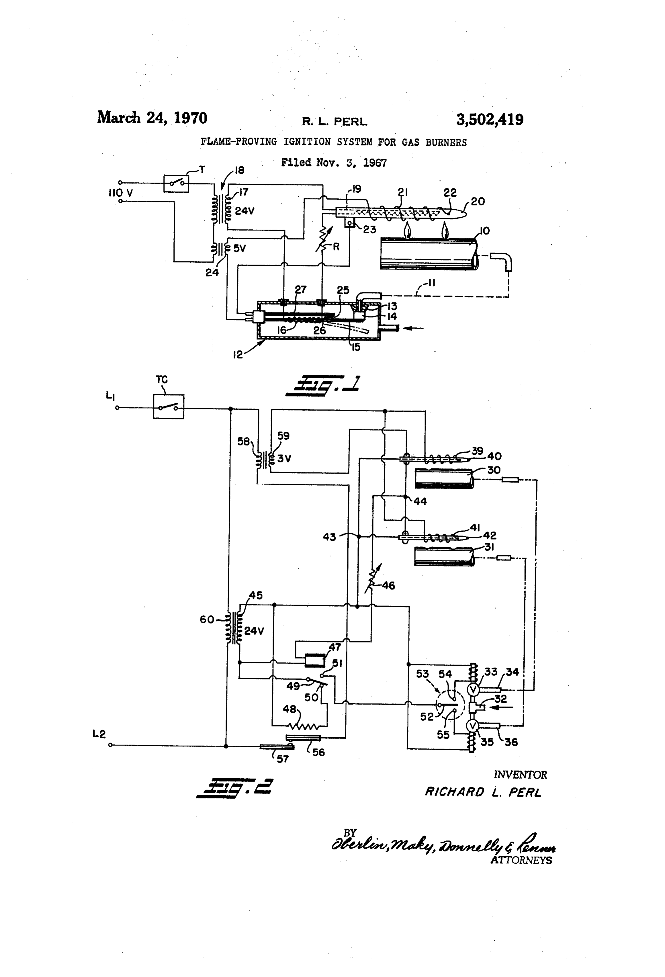
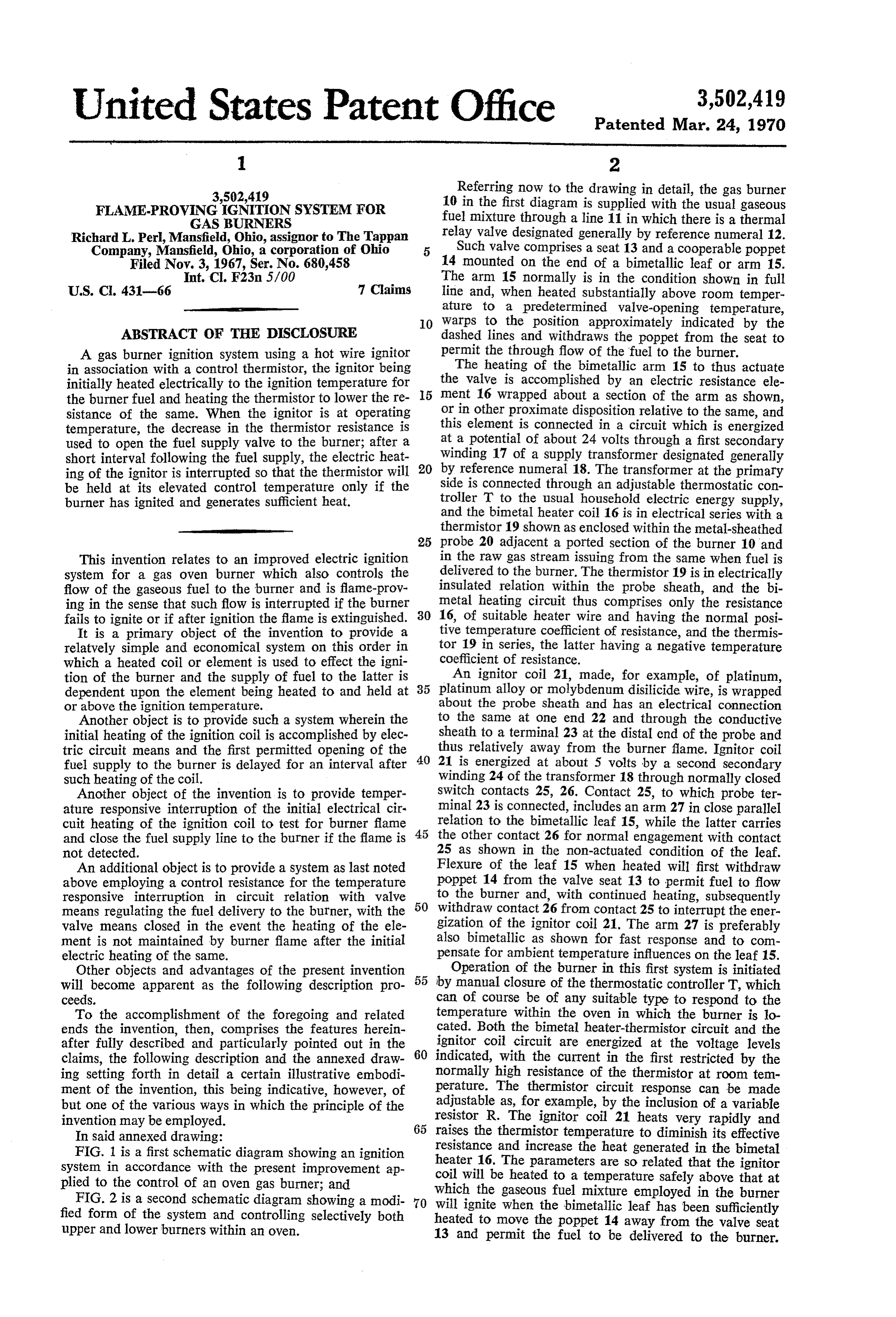
3,502,419 Referring now to the drawing in detail, the gas burner
FLAME-PROVING IGNITION SYSTEM FOR 10 in the first diagram is supplied with the usual gaseous GAS BURNERS fuel mixture through a line 11 in which there is a thermal Richard L. Perl, Mansfield, Ohio, assignor to The Tappan relay valve designated generally by reference numeral 12. Company, Mansfield, Ohio, a corporation of Ohio 5 Such valve comprises a seat 13 and a cooperable poppet Filed Nov.Int,3, CI, 1967, Ser. No. 680,458 14 mounted on the end of a bimetallic leaf or arm 15.
F23n 5/00 The arm 15 normally is in the condition shown in full
U.S. C. 431-66 7 Claims line and, when heated substantially above room temper ature to a predetermined valve-opening temperature,
O warps to the position approximately indicated by the
ABSTRACT OF THE DISCLOSURE dashed lines and withdraws the poppet from the seat to A gas burner ignition system using a hot wire ignitor permit the through flow of the fuel to the burner. The heating of the bimetallic arm 15 to thus actuate in association with a control thermistor, the ignitor being initially heated electrically to the ignition temperature for the valve is accomplished by an electric resistance ele the burner fuel and heating the thermistor to lower the re 5 or ment 16 wrapped about a section of the arm as shown, sistance of the same. When the ignitor is at operating thisinelement other proximate disposition relative to the same, and is connected in a circuit which is energized temperature, the decrease in the thermistor resistance iS at a potential of about 24 volts through a first secondary used to open the fuel supply valve to the burner; after al winding short interval following the fuel Supply, the electric heat 17 of a supply transformer designated generally ing of the ignitor is interrupted So that the thermistor will 20 by reference numeral 18. The transformer at the primary side is connected through an adjustable thermostatic con be held at its elevated control temperature only if the troller T to the usual household electric energy supply, burner has ignited and generates sufficient heat. and the bimetal heater coil 16 is in electrical series with a thermistor 19 shown as enclosed within the metal-sheathed 25 probe 20 adjacent a ported section of the burner 10 and
This invention relates to an improved electric ignition in the raw gas stream issuing from the same when fuel is system for a gas oven burner which also controls the delivered to the burner. The thermistor 19 is in electrically flow of the gaseous fuel to the burner and is flame-prov insulated relation within the probe sheath, and the bi ing in the sense that such flow is interrupted if the burner metal heating circuit thus comprises only the resistance fails to ignite or if after ignition the flame is extinguished. 30 16, of suitable heater wire and having the normal posi It is a primary object of the invention to provide a tive temperature coefficient of resistance, and the thermis relatively simple and economical System on this order in tor 19 in series, the latter having a negative temperature which a heated coil or element is used to effect the igni coefficient of resistance.
An ignitor coil 21, made, for example, of platinum, tion of the burner and the supply of fuel to the latter is 35 platinum dependent upon the element being heated to and held at alloy or molybdenum disilicide wire, is wrapped or above the ignition temperature. about the probe sheath and has an electrical connection Another object is to provide such a system wherein the to the same at one end 22 and through the conductive initial heating of the ignition coil is accomplished by elec sheath to a terminal 23 at the distal end of the probe and tric circuit means and the first permitted opening of the 40 thus relatively away from the burner flame. Ignitor coil fuel supply to the burner is delayed for an interval after 21 is energized at about 5 volts by a second secondary such heating of the coil. winding 24 of the transformer 18 through normally closed Another object of the invention is to provide temper switch contacts 25, 26. Contact 25, to which probe ter ature responsive interruption of the initial electrical cir minal 23 is connected, includes an arm 27 in close parallel cuit heating of the ignition coil to test for burner flame 45 relation to the bimetallic leaf 15, while the latter carries and close the fuel supply line to the burner if the flame is the other contact 26 for normal engagement with contact not detected. 25 as shown in the non-actuated condition of the leaf. An additional object is to provide a system as last noted Flexure of the leaf 15 when heated will first withdraw above employing a control resistance for the temperature poppet 14 from the valve seat 13 to permit fuel to flow responsive interruption in circuit relation with valve 50 to the burner and, with continued heating, subsequently means regulating the fuel delivery to the burner, with the withdraw contact 26 from contact 25 to interrupt the ener valve means closed in the event the heating of the ele gization of the ignitor coil 21. The arm 27 is preferably ment is not maintained by burner flame after the initial also bimetallic as shown for fast response and to com electric heating of the same. pensate for ambient temperature influences on the leaf 15. Other objects and advantages of the present invention 55 Operation of the burner in this first system is initiated will become apparent as the following description pro by manual closure of the thermostatic controller T, which ceeds. can of course be of any suitable type to respond to the To the accomplishment of the foregoing and related temperature within the oven in which the burner is lo ends the invention, then, comprises the features herein cated. Both the bimetal heater-thermistor circuit and the after fully described and particularly pointed out in the ignitor coil circuit are energized at the voltage levels claims, the following description and the annexed draw 60 indicated, with the current in the first restricted by the normally high resistance of the thermistor at room tem ing setting forth in detail a certain illustrative embodi perature.
ment of the invention, this being indicative, however, of The thermistor circuit response can be made but one of the various ways in which the principle of the adjustable as, for example, by the inclusion of a variable invention may be employed. resistor R. The ignitor coil 21 heats very rapidly and 65 raises the thermistor temperature to diminish its effective
In said annexed drawing:
FIG. 1 is a first schematic diagram showing an ignition resistance and increase the heat generated in the bimetal system in accordance with the present improvement ap heater 16. The parameters are so related that the ignitor plied to the control of an oven gas burner; and coil will be heated to a temperature safely above that at which
FIG. 2 is a second schematic diagram showing a modi 70 will ignite the gaseous fuel mixture employed in the burner fied form of the system and controlling selectively both heated to move when the bimetallic leaf has been sufficiently upper and lower burners within an oven. the poppet 14 away from the valve seat 13 and permit the fuel to be delivered to the burner.
Page 3
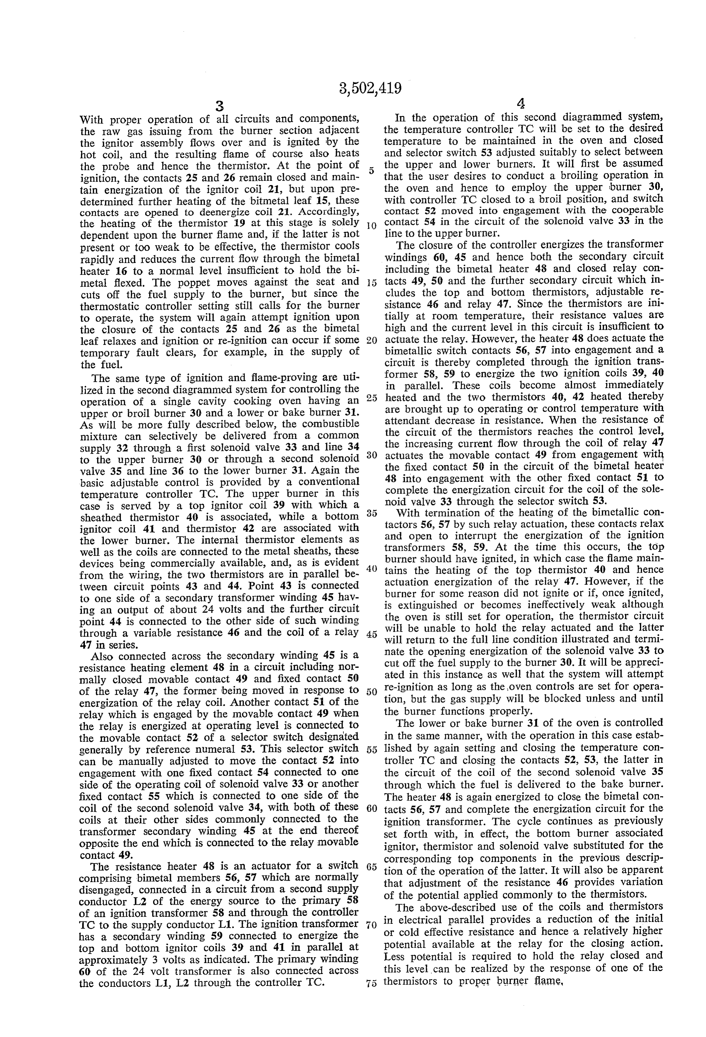
With proper operation of all circuits and components, In the operation of this second diagrammed system, the raw gas issuing from the burner section adjacent the temperature controller TC will be set to the desired the ignitor assembly flows over and is ignited by the temperature to be maintained in the oven and closed hot coil, and the resulting flame of course also heats and selector switch 53 adjusted suitably to select between the probe and hence the thermistor. At the point of 5 the upper and lower burners. It will first be assumed ignition, the contacts 25 and 26 remain closed and main that the user desires to conduct a broiling operation in tain energization of the ignitor coil 21, but upon pre the oven and hence to employ the upper burner 30, determined further heating of the bitmetal leaf 15, these with controller TC closed to a broil position, and switch contacts are opened to deenergize coil 21. Accordingly, contact 52 moved into engagement with the cooperable the heating of the thermistor 19 at this stage is solely O contact 54 in the circuit of the solenoid valve 33 in the dependent upon the burner flame and, if the latter is not line to the upper burner.
present or too weak to be effective, the thermistor cools The closure of the controller energizes the transformer rapidly and reduces the current flow through the bimetal windings 60, 45 and hence both the secondary circuit heater 16 to a normal level insufficient to hold the bi including the bimetal heater 48 and closed relay con metal flexed. The poppet moves against the seat and tacts 49, 50 and the further secondary circuit which in cuts off the fuel supply to the burner, but since the cludes the top and bottom thermistors, adjustable re thermostatic controller setting still calls for the burner sistance 46 and relay 47. Since the thermistors are ini to operate, the system will again attempt ignition upon tially at room temperature, their resistance values are the closure of the contacts 25 and 26 as the bimetal high and the current level in this circuit is insufficient to leaf relaxes and ignition or re-ignition can occur if some 20 actuate the relay. However, the heater 48 does actuate the temporary fault clears, for example, in the supply of bimetallic switch contacts 56, 57 into engagement and a the fuel. circuit is thereby completed through the ignition trans The same type of ignition and flame-proving are uti former 58, 59 to energize the two ignition coils 39, 40 lized in the Second diagrammed system for controlling the in parallel. These coils become almost immediately operation of a single cavity cooking oven having an heated and the two thermistors 40, 42 heated thereby upper or broil burner 30 and a lower or bake burner 31. are brought up to operating or control temperature with As will be more fully described below, the combustible attendant decrease in resistance. When the resistance of mixture can selectively be delivered from a common the circuit of the thermistors reaches the control level, supply 32 through a first solenoid valve 33 and line 34 30 the increasing current flow through the coil of relay 47 to the upper burner 30 or through a second solenoid actuates the movable contact 49 from engagement with the fixed contact 50 in the circuit of the bimetal heater valve 35 and line 36 to the lower burner 31. Again the 48 into engagement with the other fixed contact 51 to basic adjustable control is provided by a conventional complete the energization circuit for the coil of the sole temperature controller TC. The upper burner in this noid valve 33 through the selector switch 53. case is served by a top ignitor coil 39 with which a With termination of the heating of the bimetallic con sheathed thermistor 40 is associated, while a bottom tactors 56, 57 by such relay actuation, these contacts relax ignitor coil 41 and thermistor 42 are associated with and open to interrupt the energization of the ignition the lower burner. The internal thermistor elements as well as the coils are connected to the metal sheaths, these transformers 58, 59. At the time this occurs, the top devices being commercially available, and, as is evident burner should have ignited, in which case the flame main from the wiring, the two thermistors are in parallel be 40 tains the heating of the top thermistor 40 and hence actuation energization of the relay 47. However, if the tween circuit points 43 and 44. Point 43 is connected burner for some reason did not ignite or if, once ignited, to one side of a secondary transformer winding 45 hav is extinguished or becomes ineffectively weak although ing an output of about 24 volts and the further circuit the oven is still set for operation, the thermistor circuit point 44 is connected to the other side of such winding will be unable to hold the relay actuated and the latter through a variable resistance 46 and the coil of a relay 45 will return to the full line condition illustrated and termi 47 in series.
Also connected across the secondary winding 45 is a nate the opening energization of the solenoid valve 33 to resistance heating element 48 in a circuit including nor cut off the fuel supply to the burner 30. It will be appreci mally closed movable contact 49 and fixed contact 50 ated in this instance as well that the system will attempt of the relay 47, the former being moved in response to 50 re-ignition as long as the oven controls are set for opera energization of the relay coil. Another contact 51 of the tion, but the gas supply will be blocked unless and until relay which is engaged by the movable contact 49 when the burner functions properly.
the relay is energized at operating level is connected to The lower or bake burner 31 of the oven is controlled the movable contact 52 of a selector switch designated in the same manner, with the operation in this case estab generally by reference numeral 53. This selector switch lished by again setting and closing the temperature con can be manually adjusted to move the contact 52 into troller TC and closing the contacts 52, 53, the latter in engagement with one fixed contact 54 connected to one the circuit of the coil of the second solenoid valve 35 side of the operating coil of Solenoid valve 33 or another through which the fuel is delivered to the bake burner. fixed contact 55 which is connected to one side of the The heater 48 is again energized to close the bimetal con coil of the second solenoid valve 34, with both of these 60 tacts 56, 57 and complete the energization circuit for the coils at their other sides commonly connected to the ignition transformer. The cycle continues as previously transformer secondary winding 45 at the end thereof set forth with, in effect, the bottom burner associated opposite the end which is connected to the relay movable ignitor, thermistor and solenoid valve substituted for the contact 49. corresponding top components in the previous descrip The resistance heater 48 is an actuator for a switch 65 tion of the operation of the latter. It will also be apparent comprising bimetal members 56, 57 which are normally that adjustment of the resistance 46 provides variation disengaged, connected in a circuit from a second supply of the potential applied commonly to the thermistors. conductor L2 of the energy source to the primary 58 The above-described use of the coils and thermistors of an ignition transformer 58 and through the controller
TC to the Supply conductor L1. The ignition transformer 70 or electrical in parallel provides a reduction of the initial cold effective resistance and hence a relatively higher has a secondary winding 59 connected to energize the top and bottom ignitor coils 39 and 41 in parallel at potential available at the relay for the closing action. approximately 3 volts as indicated. The primary winding Less potential is required to hold the relay closed and 60 of the 24 volt transformer is also connected across this level can be realized by the response of one of the the conductors L1, L2 through the controller TC. thermistors to proper burner flame,
Page 4
This arrangement of course requires only a single igni transfer relation to each ignitor element and associated tion transformer as compared to two and added selector burner, the electrical resistance of the control resistors controls in a system with independent ignition circuits being variable with changes in temperature, and circuit for the burners. means for heating the ignitor elements and controlling Both diagrammed ignition systems accordingly utilize operation of the fuel Supply valve means in accordance basically a hot-wire ignitor element in association with a with changes in the resistances of the control resistors, control resistance responsive to heat initially developed said circuit means initially heating the ignitor element of by electric circuit means, with this heating required to the selected burner by opening the valve means for fuel reach a level indicative of igniting condition of the wire supply thereto upon predetermined change in the resist element. The ignitor heating to this condition results in 10 ance of the associated resistor, interrupting such initial the opening of the fuel supply to the burner and, after heating to test for burner flame heating of said resistor, a time interval, the electric heating is interrupted, with closing the valve means in response to a resistance change continuation of the fuel supply dependent upon the exist due to cooling of said resistor, the two ignitor elements ence of burner flame adequate to maintain the control and the two resistors being connected in electrical parallel resistance at its effective operating temperature. relation.
It will be appreciated that a comparable circuit could 2. In combination with a gas burner, electric hot wire be designed with employment of suitable positive tempera ignition means for the burner including a component the resistance of which varies appreciably with change in its ture coefficient of resistance elements in lieu of the de temperature, scribed thermistors, and also that the initial electric heat relay means in circuit with said ignition ing of such control element or elements might be differ 20 means so that current flow through the former is in ently provided. For example, the ignition coils have been fluenced by variation in the resistance of the latter, valve disclosed illustratively as being made of platinum or means controlled by the relay means for supplying gaseous platinum alloy because it has been determined that such fuel to the burner, means for electrically energizing the material effects catalytic ignition, i.e. causing the gas ignition means to heat the same to the ignition temperature stream to ignite at less than incandescing temperatures, 25 of the fuel and to produce by such heating a predeter and such a coil may be indirectly heated rather than by mined change in the resistance of said component, the a circuit for direct resistance heating as illustrated. One relay means being operative in response to said pre such arrangement could use a separate small heater of determined change of resistance to cause the valve means standard wire effective to heat the thermistor probe and to open and thereby supply the fuel to the burner, and an unconnected platinum coil wound about the latter. It 30 means for interrupting effective energization of the igni is also possible that the thermistor or control resistance tion means after a delay interval following the opening itself can in a proper circuit generate sufficient heat to of the valve means to test for burner flame heating of bring Such an unconnected platinum coil to the ignition Said component sufficient to maintain the relay-operating temperature. resistance value of the same.
A positive time delay in opening the ignitor circuit 35 3. The combination set forth in claim 1, wherein the relative to first supply of the fuel, in the action of the burners are disposed within a cooking oven respectively bimetallic leaf in the first diagram and in the bimetallic for baking and broiling therein, the two ignitor elements contactor in the second diagram, is preferred although are both energized in all burner operations, and the circuit an ignitor coil might be employed which will remain hot 40 means responds to the effective resistance of the parallel enough long enough for comparable testing of the flame connected control resistors.
by the noted interruption of the initial electric heating of 4. The combination set forth in claim 2, including the element, either directly or indirectly, coincident with means for delaying opening of the valve means for an the opening of the fuel line to the burner. The assured interval following initial energization of the ignition delay is of particular significance in burner systems which CalS.
operate on gaseous fuels, such as methane, which do not 5. The combination set forth in claim 2, wherein the as readily combine with air as other fuels, for example, ignition means comprises an ignitor element, which is butane. heated electrically to the fuel ignition temperature, and It will be further understood that the disclosed relay a control resistor as the variable resistance component. functions can be served also by solid state controls having 50 6. The combination set forth in claim 5, wherein the equivalent operating modes. control resistor is in heat transfer relation to the ignitor Other modes of applying the principle of the invention element for heating of the former by the latter to produce may be employed, change being made as regards the the pre-determined change in the resistance thereof. details described, provided the features stated in any of 7. The combination set forth in claim 6, including the following claims or the equivalent of such be means for delaying opening of the valve means for an employed. interval following initial energization of the ignition I, therefore, particularly point out and distinctly claim CaS.
as my invention: References Cited 1. In combination with first and second gas burners, UNITED STATES PATENTS and a gaseous fuel supply therefore including valve means 60 operable selectively to supply the fuel to the first or the 2,549,633 4/1951 Ottmar ---------- 431--66 X second burner; a flame-proving electric ignition system 3,151,661 10/1964 Matthews --------- 431-66 X for the burners, comprising an ignitor element positioned 3,393,038 7/1968 Burkhalter et al. ------ 431-66 in the discharge of the fuel mixture from each burner and adapted to be heated to a temperature which will 65 EDWARD G. FAVORS, Primary Examiner cause it to ignite the mixture, a control resistor in heat
Provenance
- Collection
- Cited prior art
- Original PDF
- patentimages.storage.googleapis.com →
- Filed
- 1967-11-03
- Pages
- 4
- Method
- pdftotext (the PDF's own text layer) + pdftoppm 300dpi page scans
- Source
- Google Patents bibliographic record
- Granted
- 1970-03-24
- Inventors
- Richard L Perl; Tappan Co
- Transcribed from
- patentimages.storage.googleapis.com →