patent · US4219072
Phase change material heat exchanger
26 August 1980
Page 1 — bibliographic record
United States Patent (19) (11) 4,219,072 Barlow, Sr. 45) Aug. 26, 1980 (54) PHASE CHANGE MATERAL, HEAT 4,146,087 3/1979 Johansson ......................... 165/104 S EXCHANGER Primary Examiner-Albert W. Davis (76 Inventor: Donald W. Barlow, Sr., Rte. 3, Box Attorney, Agent, or Firm-Duckworth, Hobby, Allen &
21) Appl. No.: 876,672 57 ABSTRACT 22 Filed: Feb. 10, 1978 A phase change material heat exchanger wherein the Int, Cli........................................ F28D 15/00 latent heat of a substance as its physical state changes (51) from solid to liquid, and vice versa, is utilized as a heat 52 U.S. C. .................................. 165/32; 165/104 S; storage medium. Structure is also disclosed whereby a
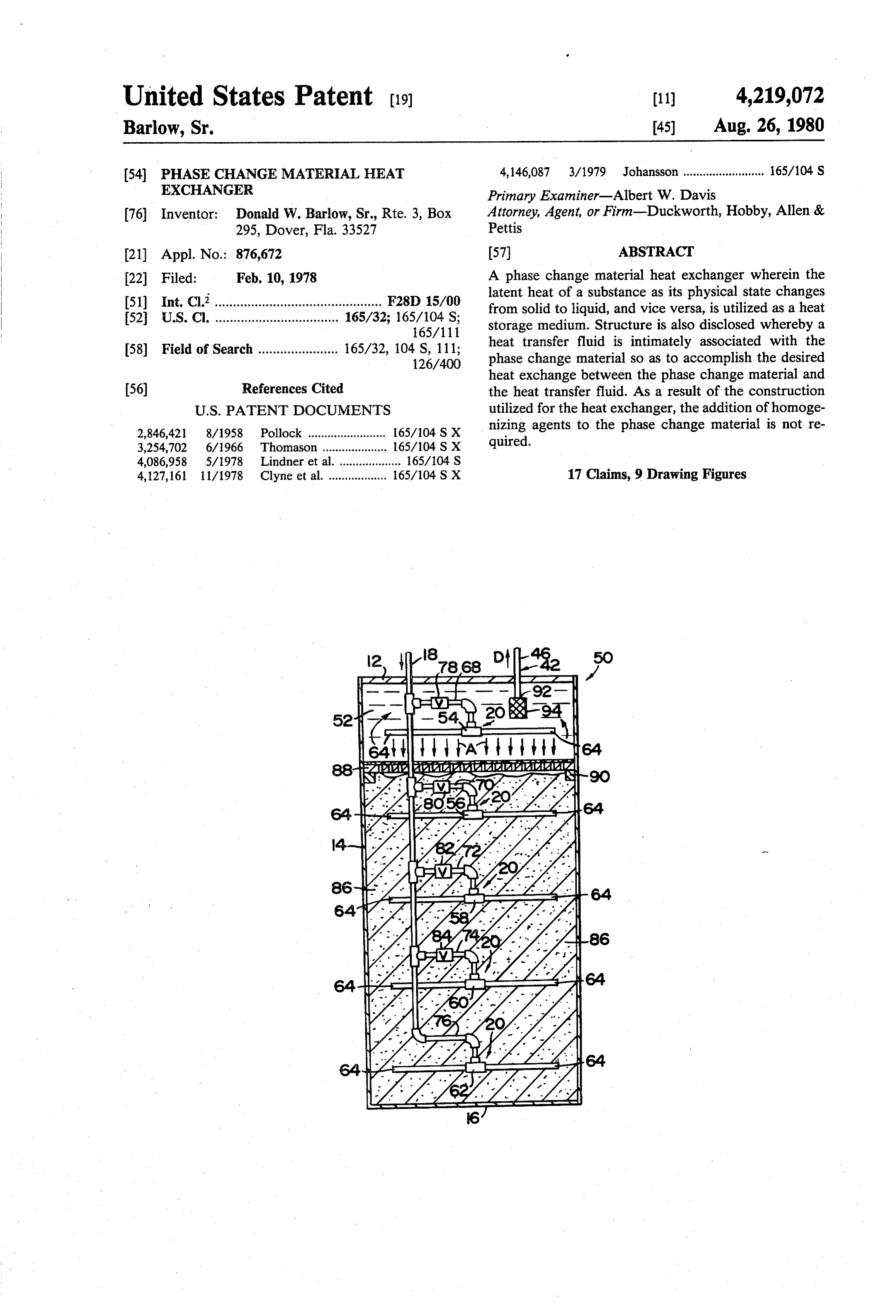
(58) Field of Search ...................... 165/32, 104 S, 111; heat transfer fluid is intimately associated with the 126/400 phase change material so as to accomplish the desired heat exchange between the phase change material and (56) References Cited the heat transfer fluid. As a result of the construction
nizing agents to the phase change material is not re 3,254,702 6/966 Thomason .. ... 165/104 S X quired.
4,086,958 5/1978 Lindner et al. 165/104 S 4,127,161 11/1978 Clyne et al. .................. 165/104 S X 17 Claims, 9 Drawing Figures
Page 2
Drawing sheet — no readable text.
Page 3
Drawing sheet — no readable text.
Page 4
phase change which is capable of being stored by the
PHASE CHANGE MATERIAL, HEAT EXCHANGER phase change material.
U.S. Pat. No. 2,677,664, to Telkes teaches the use of
BACKGROUND OF THE INVENTION Glauber's salt (sodium sulfate decahydrate) as a suitable 1. Field of the Invention phase change material. However, as discussed in that The present invention relates to a phase change mate patent, this material and other similar salt hydrates do rial heat exchanger wherein a phase change material not easily return to their normal hydrate form when comprising a salt selected for its relatively high latent giving up heat at their critical temperature without heat is utilized as a heat storage medium. The heat ex O external agitation or stirring. That is to say, free water changer of the invention comprises a substantially is often formed in the supersaturated solutions. This will closed container into which the phase change material not only tend to damage the container and heat storage is placed. Then, using a system of conduits and dis system, but also deleteriously affects the system's effi charge heads, a heat transfer fluid is passed through the ciency. Telkes '664 teaches that this problem may be phase change material so as to allow a heat energy 15 overcome by the addition of borax (sodium tetraborate exchange therebetween. This heat transfer takes place decahydrate) into the salt hydrate solution. The same substantially at the heat of fusion of the phase change patent recognizes that mechanical means for external material so as to make optimum use of the material's agitation of sealed containers of the heat storage me latent heat. By virtue of the construction of the phase dium would be possible, but is undesirable because of change material heat exchanger the use of homogeniz the costs and mechanics involved.
ing agents in combination with the phase change mate 20 U.S. Pat. No. 3,986,969, also to Telkes teaches yet rial is not necessary. In a preferred embodiment the another solution to the problem of free water formation phase change material heat exchanger is utilized as a comprising not only the addition of borax as a nucleat heat storage facility in combination with a solar heat ing agent, but also the addition of attapulgus clay (hy collector of state of the art construction. Solar heat is drous magnesium aluminum silicate) as an homogeniz absorbed by the heat transfer fluid and stored by the 25 ing agent. That patent teaches that the composition phase change material placed within the heat ex including the salt hydrate plus borax and clay maintains changer. If solar heat is not currently available, heat the salt hydrate in suspension during repeated heating previously stored could be used to raise the temperature and cooling cycles.
of the heat transfer fluid. Still other examples of the use of phase change mate
Recent developments in the art of solar heating and foundininheat rials the storage and heat exchange devices are following U.S. Patents: Nos.
cooling have created a great need for some means of Telkes 2,677,367 efficiently storing the energy obtained from the sun for Tekes 2,808,494 later use, such as at night or on cloudy days. A similar Van Vechten 3,937,209 need has also been recognized with regard to the effi 35
cient operation of liquid-to-air heat pump systems. Such Switzgable 3,991,936 heat storage facilities are commonly referred to as heat Chubb 3,997,001 sinks, and the prior art teaches numerous devices for the Telkes 4,010,620 construction and operation of such heat storage facili In addition to the crystallization/recrystallization ties.
Perhaps the simplest of such devices consists essen problems discussed above, these patents also identify tially of a large holding tank into which the fluid which certain other problems found in state of the art heat has been heated by the sun is collected for subsequent exchanger devices using phase change material. For usage, such as a home's hot water supply. Other devices example, inasmuch as the phase change material usually teach the storage of heat within rocks placed inside a 45 consists essentially of a salt or a salt hydrate, direct container through which the heated fluid is allowed to contact of the phase change material with water is un flow. Most state of the art heat pumps utilize the atmo of desirable. Furthermore, because of the corrosive nature sphere as a heat sink, either expelling waste heat to the the phase change materials utilized, relatively sophis air or extracting heat from the atmosphere, depending ticated and complex mechanical scraping, cleaning and upon the mode of operation of the heat pump. 50 agitating devices must often be utilized in the systems. Each of these state of the art devices is relatively Accordingly, it is clear that there is a great need in inefficient, and this inefficiency has become a primary the art for a heat exchanger construction wherein a concern because of the high energy associated with phase change material may be efficiently utilized for the operating devices using these primary types of heat purpose of alternately storing and releasing heat energy. storage facilities. At least in partial solution of these 55 Such a heat exchanger device should be suitable for use problems, the current state of the art does teach what in combination with existing heating and cooling sys may be termed as secondary, or second generation, heat tems and should be of relatively simple construction so storage facilities. as to provide long lasting, maintenancefree operation. These second generation heat storage facilities basi For purposes of efficiency, it would also be desirable to cally teach the use of a heat storage medium comprising 60 utilize the phase change material in an unadulterated a phase change material having a heat of fusion of more form without the necessity of incorporating nucleating than 50 BTU per pound. By "phase change material' is and homogenizing agents.
meant a material which undergoes a physical change, SUMMARY OF THE INVENTION such as from a crystal to a liquid or from an hydrated crystal to a dehydrated crystal, at a functional tempera 65 The present invention relates to a phase change mate ture. The bulk of the prior art teaches the use of salt rial heat exchanger wherein the latent heat of fusion of hydrates as the phase change material, and it is the a phase change material is utilized as a heat storage latent heat absorbed or expelled in accomplishing the medium. With the advent of solar-based heating and
Page 5
Drawing sheet — no readable text.
Page 6
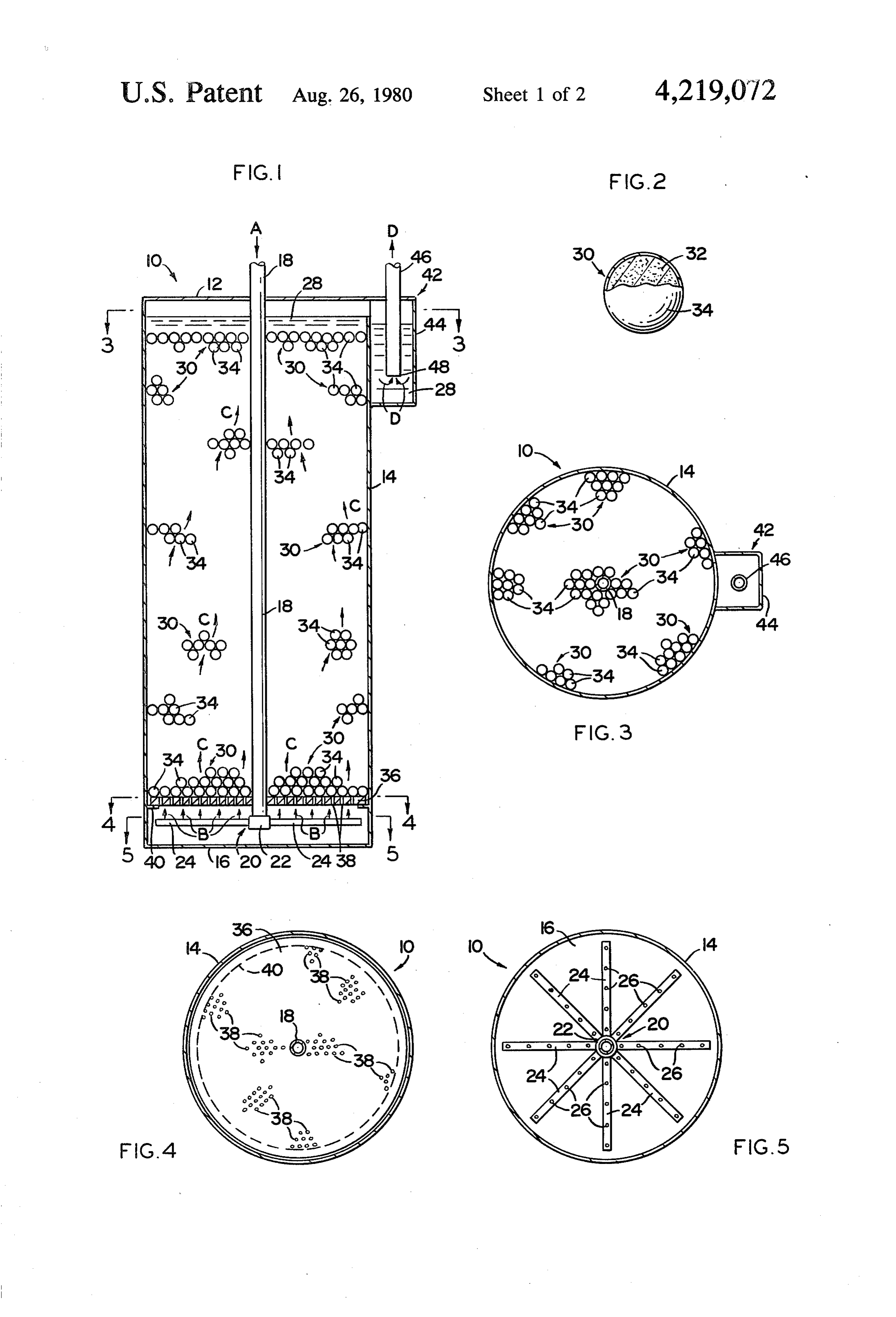
discharge head positioned above the segregator means FIG 2, is a detail view, partially in section, of the would still be available for the flow of heat transfer fluid phase change material. . . . . . therethrough. In such a situation this flow onto the top FIG. 3 is a sectional view taken along line 3-3 of of the "frozen" mass of phase change material would FIG 1.
tend to melt that material as its heat of fusion was ob- 5 FIG. 4 is a sectional view taken along line 4-4 of tained. Then, owing to the serial construction of dis FIG. 1.
charge heads and corresponding, check valves, succes FIG. 5 is a sectional view taken along line 5-5 of sively lower discharge heads would open, eventually FIG.1.
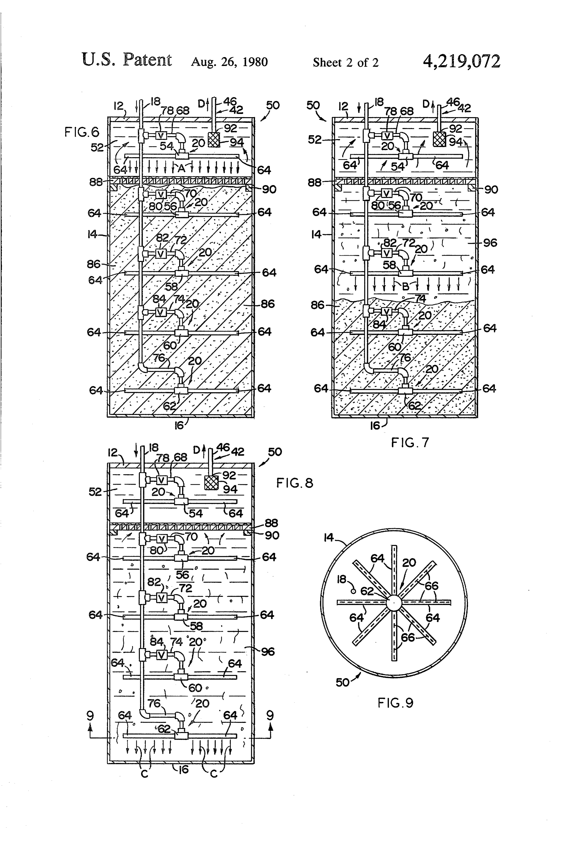
resulting in a fluid phase change material bed from top i FIG. 6 is an elevational view, in section, of a second to bottom. . . . . .. . . .. . . . 10 embodiment of the phase change material heat ex As the heat transfer fluid passes from the inlet means, changer showing its operation when the entire mass of through the phase change material, and back to the top phase change material is frozen. . w of the container, the heat transfer fluid is removed from FIG. 7 is a sectional view similar to that of FIG. 6 the heat exchanger by fluid outlet means comprising a showing the operation of the phase change material conduit disposed in fluid communicating relation, to the 15 heat exchanger when only a portion of the phase heat transfer fluid substantially adjacent the top of the change container. As a precautionary measure the end of the * FIG. material is in a fluid state. 8 is a sectional view similar to that of FIG. 6 outlet means within the container is provided with a showing the preferred mode of operation for this em filter to prevent any phase change material from enter ing the system to, which the heat exchanger is con bodiment of the phase change material heat exchanger. FIG. 9 is a sectional view taken along line 9-9 of nected. - . . . . FIG. 8. ,;, , , , , - Having thus set forth the basic construction for the phase change material heat exchanger of this invention, throughout the several views of the drawings. parts Similar reference characters refer to similar attention is invited to certain considerations with regard to the phase change material and the heat transfer fluid. 25
As stated above in the Description of the Prior Art, the
DETAILED DESCRIPTION
The present use of phase, change material as heat sinks is known in phase change materialinvention relates to a construction for a the prior art. In fact, each of the patents referred to heat exchanger, a primary em above, disclose such materials. Of course, a particula bodiment of said heat exchanger being generally indi cated as 10 in the view of FIG.1. As shown therein heat phase change material is chosen with primary regard to 30 the operating conditions which the system will encoun exchangertop 12, side 10 comprises a container means including 14 and bottom 16 to define a substantially ter. It is therefore intended that the scope of the present closed volume. A heat transfer fluid inlet means com invention does include any phase change material pos prising an inlet conduit 18 is disposed in fluid communi sessing a latent heat of fusion appropriate for the operat ing conditions of the heat exchanger. Nevertheless, 35 cating relation with the interior of the container means and includes a discharge means generally indicated as prime consideration in the development of this, inven 20 disposed on the interior end of inlet conduit 18. As tion has been given to salts and salt hydrates, such as, for example, calcium chloride and sodium sulfate decahy most clearly seen in the view of FIG. 5, discharge means 20 comprises a discharge head 22 including a
With regard to the heat transfer fluid, reference is 40 plurality of radially extending spoke means 24 disposed again made to the parameters set forthin the preceding thereon. Each of the spoke means 24 further includes a brief description. In the encapsulated embodiment of plurality of inlet apertures 26 formed therethrough so as the invention virtually any heat transfer fluid may be to allow passage of a heat transfer fluid. This flow of heat transfer fluid is indicated schematically in the view utilized for the reason that the fluid will not come into of direct contact with the phase change material. It is 45 FIG. 1 by directional arrows A through inlet conduit contemplated that this encapsulated embodiment will 18, B from inlet apertures 26, and C through the interior be particularly useful in installations where the use of of the container means. As further shown in the view of water as the heat transfer fluid is desired. Of course, FIG.1, heat transfer fluid 28 substantially fills the inte other fluids could also be utilized. However, in the - riorPhase of the container means. change material heat exchanger 10 further second embodiment wherein the heat transfer fluid 50 comprises a phase change material generally indicated intimately contacts the phase change material itself, water as the heat transfer fluid is not acceptable. In this as 30 placed within the container means and surrounded embodiment experimentation has shown hydrocarbon by heat transfer fluid 28. Notwithstanding the partial and silicon oils to be most efficacious. : ". . . . . . . representation of FIG. 1, it is to be understood that The invention accordingly comprises the features of 55 . phase change material 30 is placed within the container construction, combinations of elements, and arrange means so as to substantially fill its closed volume. With ment of parts which will be exemplified in the construc particular regard to the detailed view of FIG. 2, it can tions hereinafter set forth, and the scope of the inven be seen that phase change material 30 comprises a salt tion will be indicated in the claims." - 32, a predetermined quantity of which is enclosed by capsule means 34. In this preferred embodiment salt 32
BRIEF DESCRIPTION OF THE DRAWINGS 60 consists essentially of calcium chloride, and capsule For a fuller understanding of the nature and objects. means 34 is formed from a plastic material. Inasmuch as of the invention, reference should be had to the follow salt 32 is enclosed by the plurality of capsule means 34, ing detailed description taken in connection with the heat transfer fluid 28 of this embodiment may comprise accompanying drawings, in which:. . . . . . . . 65 water. Ofcourse, virtually any relatively low viscosity FIG. 1 is an elevational view, in section, of a first fluid may be utilized as heat transfer fluid 28 so long as embodiment for the phase change material heat ex the particular fluid chosen is substantially inert with changer. . . . . . . ... . . . . . .. . . . regard to.capsule means 34. ,
Page 7
As best seen in the views of FIGS, 1 and 4, phase further comprising a plurality of orifices 66 formed change material 30 is maintained in a fixed, spaced apart therethrough and oriented in the direction of bottom 16. relation with regard to discharge means 20 by capsule The remaining discharge heads 54, 56, 58 and 60 are support means 36. As shown in those views capsule similarly constructed as indicated in the views of FIGS. support means 36 comprises a plate including a plurality 6, 7 and 8. Those figures also illustrate the fact that each of heat transfer fluid apertures formed therethrough. of the discharge heads 54-62 is interconnected in fluid Capsule support means 36 is maintained in the position communicating relation to inlet conduit 18 by a corre shown in FIG. 1 by its placement around inlet conduit sponding plurality of discharge conduits 68, 70, 72, 74 18 onto support ledge 40 formed on the interior of side and 76, 14. 10 In order to regulate the open/close condition of each A heat transfer fluid outlet means generally indicated of the discharge heads 54-60, adjustable check valves as 42 is formed substantially adjacent top 12 of heat 78, 80, 82 and 84 are disposed in fluid flow regulating exchanger 10 and in fluid communicating relation to position in corresponding discharge conduits 68-74. heat transfer fluid 28. As most clearly seen in the view Each of the check valves 78-84 is adjusted so as to open of FIG. 1, heat transfer fluid outlet means 42 comprises 15 only upon reaching a predetermined pressure of heat overflow well means 44 into which the warm or cool transfer fluid 52. Of course, it should be obvious that fluid 28 will flow, and outlet conduit 46 one end 48 of discharge head 62 is always in an open position, for no which is in fluid communicating relation to fluid 28 check valve is provided. Check valve 84 requires rela with end well means 44. Accordingly, fluid 28 is re tively less pressure to open than does check valve 82. moved from well means 44 through conduit 46 as indi 20 Similarly, check valve 82 requires less pressure to open cated by directional arrows D. than does check valve 80, and check valve 78 requires In operation, phase change material heat exchanger the greatest pressure to open. By virtue of this construc 10 is operatively connected to a work unit, such as, for tion, heat transfer fluid 52 will be discharged from only example, a heat pump, during the operation of which an one of the discharge means 20 at any given operating exchange of heat energy is desired. In this example 25 condition, and this will be explained in greater detail wherein phase change material 30 comprises calcium below. " chloride salt 32, the heat transfer fluid 28 utilized is Now with particular attention to the view of FIG.6, water. Calcium chloride has a melting point of about it can be seen that the interior of the phase change mate 81 F. and a latent heat of fusion equivalent to approxi rial heat exchanger 50 is substantially filled with phase mately 8,774 BTU per cubic foot. Dependent upon the 30 change material 86 illustrated in the view of FIG. 6 in mode of operation and, therefore, the temperature of its substantially solid or "frozen' state. A segregator incoming transfer fluid 28, heat energy is stored in or means 88 is disposed at the top of phase change material absorbed from calcium chloride salt 32. This heat trans 86 and supported in that position by segregator ledge fer is accomplished with extreme efficiency for the 90. As will be described below, segregator means 88 is reason that fluid 28 intimately contacts each of the cap 35 permeable to heat transfer fluid 52, but substantially sules 34 including salt 32 placed therein. This intimate impermeable to phase change material 86, which in this contact also has a stirring or mixing effect on the phase embodiment comprises sodium sulfate decahydrate salt. change material 30 so as to provide for truly reversible Inasmuch as heat transfer fluid 52 will contact the phase physical state changes of salt 32 from crystal to liquid change material 86 intimately, it is to be understood that and vice versa. Presuming that phase change material heat transfer fluid 52 and phase change material 86 are 30 is in an operating mode for the collection of heat to be immiscible. Again, with specific regard to the energy, salt 32 within each of the capsules 34 absorbs embodiment of FIGS. 6-9, the heat transfer fluid 52 heat from the heat transfer fluid 28 passing therearound, comprises a low viscosity hydrocarbon oil. Of course, and the cooled fluid 28 then exits through outlet means silicon-type fluids could also be utilized. 42 to begin another cycle. 45 Finally, with regard to structural elements, phase It is, of course, to be understood that by virtue of the change material heat exchanger 50 further comprises fact that phase change material heat exchanger 10 is heat transfer fluid outlet means generally indicated as 42 preferably operated at the heat of fusion of salt 32, rela and comprising an outlet conduit 46 disposed in fluid tively large quantities of heat may be retained and/or communicating relation to the interior of the container rejected owing to the salt's latent heat of fusion. 50 means. As shown in the views of FIGS. 6, 7 and 8, end Attention is now invited to the views of FIGS. 6-9, 92 of outlet conduit 46 disposed within heat transfer inclusive, wherein a second embodiment of the phase fluid 52 is provided with a filter means 94. Filter means change material heat exchanger is generally indicated as 94 is primarily intended as a precautionary device to 50. Inasmuch as many structural elements of this second preclude entry of phase change material 86 into the embodiment 50 are identical to those of the primary 55 system serviced by phase change material heat ex embodiment 10, similar reference numerals have been changer 50.
utilized where appropriate. Having thus set forth the structural elements of this As seen in the view of FIG. 6, this embodiment of second embodiment and their relationships to each phase change material heat exchanger 50 also comprises other, attention is now invited to the following descrip a container means having a top 12, sides 14, and a bot 60 tion of the operation of phase change material heat tom 16 to define a substantially closed volume. An inlet exchanger 50 as shown in FIGS. 6, 7 and 8. conduit 18 is provided for the introduction of a heat The view of FIG. 6 illustrates the heat exchanger 50 transfer fluid, herein designated as 52, into the container wherein virtually all of the sodium sulfate decahydrate means. Discharge means 20 of this embodiment com phase change material 86 is in a solid state. Accord prises a plurality of discharge heads identified as 54, 56, 65 ingly, orifices 66 of discharge heads 62, 60, 58 and 56 are 58, 60 and 62. As most clearly seen in the view of FIG. closed. The pressure of heat transfer fluid 52 will rise to 9, discharge head 62 comprises a plurality of radially the point where check valve 78 opens, and heat transfer extending spoke means 64, each of said spoke means 64 fluid 52 will be discharged from discharge head 54 as
Page 8
indicated by arrows A. The relatively, warmer heat features, of the invention herein described, and all state transfer fluid 52 will pass through segregator, means 88 ments of the scope of the invention which, as a matter of and, in effect, thaw phase change material 86 by raising language, might be said to fall therebetween. its temperature to its heat of fusion, which for sodium : . Now, that the invention has been described, what is sulfate decahydrate is about 87 F. This action will claimed is: ; , . . . . . . . . . . . . - create a slurry, or fluidized bed, designated by the nu 1. A phase change material heat exchanger, said heat meral 96 in FIGS. 7 and 8 and comprising a supersatu exchanger.comprising: container means defining a sub rated solution of sodium sulfate decahydrate plus heat stantially closed volume; heat transfer fluid inlet means transfer fluid 52. It is within this slurry 96 that the most disposed in fluid communicating relation with the inte efficient heat exchange takes place, utilizing the latent 110 ingrior of said container means, said inlet means compris a plurality of discharge heads serially connected to heat of fusion of the phase change material 86.
Then, as more of the phase change material-86 said inlet means by a corresponding plurality of dis "melts" successively lower-discharge heads open. As 'charge conduits, said inlet means further comprising illustrated in the view of FIG.7, slurry.96 has formed so N-1 check valve means, wherein N equals the number as to permit passage of heat transfer fluid 52 from dis 15 of said plurality of discharge heads, one of said check charge head 58, as indicated by directional arrows B. valve means being disposed in fluid flow regulating Finally, FIG. 8 illustrates the preferred physical con position upstream of each of said plurality of discharge dition of heat exchanger 50 wherein substantially all of heads other than the one of said plurality of discharge the phase change material 86 is contained within slurry heads positioned in closest proximity to the bottom of 96, so that heat transfer fluid 52 flows from discharge 20 said interior, each of said check valve means including head 62 as indicated by directional arrows C. This is adjustment means whereby each of said valve means is preferred for the reason that substantially all of the adjustable to open at a predetermined pressure; a phase phase change material 86 is being utilized for heat trans change material placed within said container means, fer at the latent heat level. Furthermore, inasmuch as said phase change material being utilized in sufficient heat transfer fluid 52 enters at the bottom of the con 25 quantity to fill at least most of said container means; tainer means, slurry 96 is in a relatively constant state of heat transfer fluid outlet means disposed in fluid com agitation thereby providing for efficient, reversible municating relation with the interior of said container transition of the sodium sulfate decahydrate back and means, said outlet means being in spaced apart relation forth from its solid to liquid stages without the creation to said inlet means; and a heat transfer fluid flowing of free water. 30 from said inlet means through said phase change mate The heat transfer cycle is concluded by the removal rial to said outlet means, the settings of said adjustment of either the heated or warmed transfer fluid 52 through means being graduated so that said heat transfer fluid outlet means 42 as indicated by directional arrow B. will flow from but one of said discharge heads depen It is to be understood that there are numerous phase dent upon the physical state of said phase change mate change materials which lend themselves to various 35 rial, whereby an exchange of heat energy may take useful temperature plateaus. The example illustrated in place between said phase change material and said heat the views of FIGS. 6-9 utilizes sodium sulfate decahy transfer fluid.
drate as the phase change material for use in conjunc 2. A phase change material heat exchanger as in claim tion with a heat pump for heating and cooling a home. 1 wherein said phase change material comprises calcium As previously stated, the melting point of sodium sul chloride fate decahydrate is approximately 87 F. This material is 3. A phase change material heat exchanger as in claim relatively inexpensive, commercially available, and has 1 wherein said phase change material comprises sodium a storage capacity in excess of 10,000 BTU per cubic sulfate decahydrate.
foot. Because this salt hydrate is slightly basic, it has the 4. A phase change material heat exchanger as in claim additional advantage of being relatively non-corrosive 45 1 wherein said heat transfer fluid comprises a liquid. to the metals normally utilized in such systems. It 5. A phase change material heat exchanger as in claim should also be noted that dehydration of the salt hy 4 wherein said liquid comprises water.
drate does not occur due to the light layer of heat trans 6. A phase change material heat exchanger as in claim fer fluid covering and sealing the material, even when 4 wherein said liquid comprises a hydrocarbon oil. the salt is "frozen,' above the segregator means 88. As 50 7. A phase change material heat exchanger as in claim latent heat is removed from the liquid salt hydrate crys 4 wherein said liquid comprises a silicon oil. tallization begins due to the seeding effect of the super 8. A phase change material heat exchanger as in claim saturated solution. However only very small crystals 1 wherein each one of said plurality of discharge heads form, and these small crystals are interlarded with the comprises a plurality of radially extending spoke means. immiscible heat transmitting fluid. The crystals of the 55 9. A phase change material heat exchanger as in claim phase change material then are maintained in a slurry, 8 wherein each one of said plurality of discharge heads or fluidized bed, and remain so during the normal up further comprises a plurality of orifices formed through ward movement of the heat transfer liquid. a wall of each of said plurality of spoke means, each of It will thus be seen that the objects set forth above, said plurality of orifices communicating with said inte among those made apparent from the preceding de 60 rior and being oriented toward the bottom of said inte scription, are efficiently attained and since certain 1O.
changes may be made in the above construction without 10. A phase change material heat exchanger as in departing from the scope of the invention, it is intended claim 1 wherein said adjustment means are set so that that all matter contained in the above description or the one of said check valve means most remote from shown in the accompanying drawings shall be interpret 65 said one discharge head in closest proximity to said ted as illustrative and not in a limiting sense. bottom requires the greatest heat transfer fluid pressure It is also to be understood that the following claims to open and the one of said check valve means adjacent are intended to cover all of the generic and specific the discharge head closest to said one discharge head
Page 9
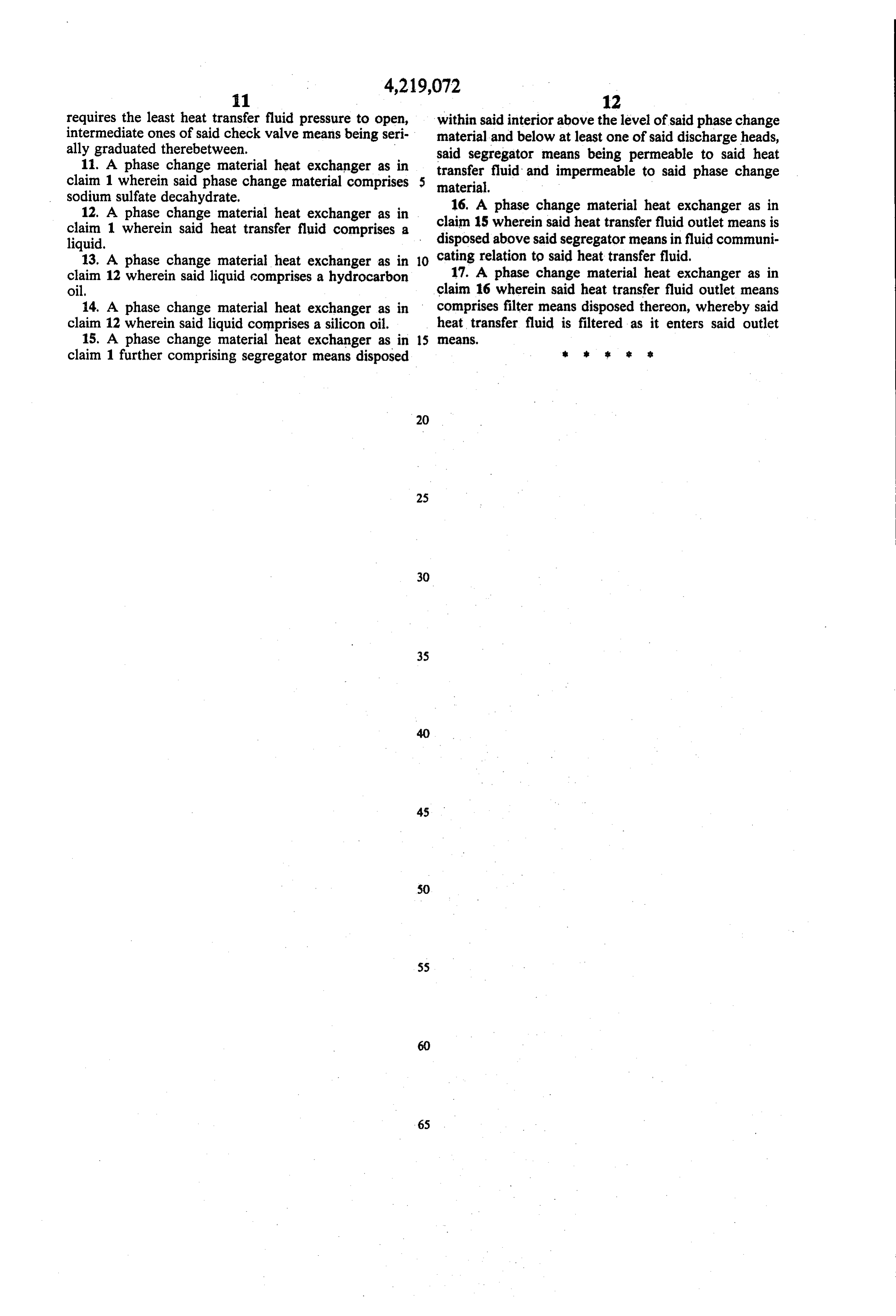
requires the least heat transfer fluid pressure to open, within said interior above the level of said phase change intermediate ones of said check valve means being seri material and below at least one of said discharge heads, ally graduated therebetween.
11. A phase change material heat exchanger as in said segregator means being permeable to said heat claim 1 wherein said phase change material comprises material. fluid and impermeable to said phase change transfer sodium sulfate decahydrate. 16. A phase change material heat exchanger as in 12. A phase change material heat exchanger as in claim 15 wherein said heat transfer fluid outlet means is claim 1 wherein said heat transfer fluid comprises a disposed above said segregator means in fluid communi liquid.
13. A phase change material heat exchanger as in 10 cating relation to said heat transfer fluid. claim 12 wherein said liquid comprises a hydrocarbon 17. A phase change material heat exchanger as in oil. claim 16 wherein said heat transfer fluid outlet means 14. A phase change material heat exchanger as in comprises filter means disposed thereon, whereby said claim 12 wherein said liquid comprises a silicon oil. heat transfer fluid is filtered as it enters said outlet 15. A phase change material heat exchanger as in 15 eaS.
claim 1 further comprising segregator means disposed is 8 &
Provenance
- Collection
- Cited prior art
- Original PDF
- patentimages.storage.googleapis.com →
- Filed
- 1978-02-10
- Pages
- 9
- Method
- pdftotext (the PDF's own text layer) + pdftoppm 300dpi page scans
- Source
- Google Patents bibliographic record
- Granted
- 1980-08-26
- Inventors
- Donald W. Barlow, Sr.
- Transcribed from
- patentimages.storage.googleapis.com →