patent · US3384568
Electrodialysis apparatus having chord electrodes
21 May 1968
Page 1
Drawing sheet — no readable text.
Page 2
Drawing sheet — no readable text.
Page 3
Drawing sheet — no readable text.
Page 4
Drawing sheet — no readable text.
Page 5
United States Patent Office Patented May 21, 1968
in FIG. 3, FIG. 5 is a schematic diagram illustrating one 3,384,568 example of electrodialysis apparatus and piping for re
ELECTRODALYSES APPARATUS HAVENG moving precipitate produced inside the cathode compart CHORED ELECTRODES ment when a cord electrode comprises the cathode of
Masaaki Kato, Yokohana, Ryozo Koinori, Tokyo, and the apparatus.
Mitsunobu Fukumoto, Yokohama, Japan, assignors to FIG. 6 is a schematic diagram illustrating a system of Asahi Kasei Kogyo Kabushiki Kaisha, Osaka, Japan, a inlet and outlet solution flow through a membrane stack corporation of Japan
Filed Nov. 19, 1963, Ser. No. 324,744 and the re-circulating of the concentration stream through Claims priority, application Japan, Nov. 22, 1962, the electrode compartments; and FIGS. 7 to 10 are gen 37/51,095; Mar. 12, 1963, 38/11,390 O erally piping schematics for electrode rinse solution when 9 Claims. (C. 204-301) at least one electrode is employed in an electrodialysis apparatus according to the invention.
Heretofore electrodes of electroconductive material in
ABSTRACT OF THE DISSLOSURE the form of planes, grates or cylinders have been em A multicell electrodialyzer which comprises a plurality ployed in electrodialysis apparatus using ion-exchange of dilution compartments and concentration compart resin membranes. However, when such electrodes were ments sectioned with anion permselective resin mem used as cathodes in the presence of solution containing branes and cation permselective resin membranes alter ions such as Catt, Mg++, HCO and SO , pre nately, and electrodes at the outermost ends of the ap cipitates such as magnesium hydroxide, calcium sulfate, paratus. The electrodes each consist of a plurality of 20 calcium carbonate etc. formed on the surface of the cords made of electroconductive material which prevents cathodes and in the cathode compartment due to the accumulation of insoluble precipitate on the electrode usual electrode reaction and accumulated on the cathode surfaces or in the electrode compartment. surface and in the cathode compartment causing the -adress samar clogging of the flow of solution in the cathode compart 25 ments and the decrease in current density by the accum
This invention relates to improvements in apparatus ulation of the precipitates. Generally such accumulation used for the electrodialysis of aqueous solutions contain of precipitate cannot be prevented from occuring by ing inorganic or organic salts which are to be removed merely intermittently increasing the rate of solution flow therefron. into the electrode compartments. Thus continuous and More particularly, this invention relates to apparatus 30 safe electrodialysis over a long period was heretofore having cord-like electrodes therein and has an object to often interrupted unless an acid was added to the cathode prevent or overcome the accumulation of insoluble pre rinse solution. In the same manner, when the heretofore cipitates on the surfaces of electrodes since such ac known electrodes were used as anodes and a solution cumulation causes the clogging of solution-flow inside the containing compounds such as Sodium stearate were used electrodes and the electrode compartments and conse as the anode rinse solution in the absence of free alkalis quently decrease the available current density. insoluble free organic stearic acid accumulated on the During the electrodialysis of aqueous solutions effected anode surface or in the anode compartments causing the in multi-cell electrodialysis apparatus having alternating same as mentioned above. In order to prevent the ac dilution and concentration compartments defined by 40 cumulation of the precipitates in the examples Stated spaced alternating anion and cation permselective resin above, acid had to be added in the cathode rinse solution membranes, the electrodialysis heretofore often inter or into the cathode compartment, and alkali in the anode rupted to remove the accumulation of the insoluble pre rinse solution of anode compartment respectively for con cipitate on the surfaces of electrodes and in the electrode ducting electrodialysis successfully. In most cases of elec compartments, or the addition of Some chemicals was trodialysis processes using ion exchange resin membranes, necessary for the purpose as mentioned above. The ap such procedures as described above have made it in paratus of the present invention enables the continuous possible to supply the inlet or outlet solution of concen electrodialysis at a good efficiency by providing cordlike tration or dilution stream directly into the electrode com electrodes composed of a plurality of cords made of partment. As in most cases of electrodialysis processes electroconductive material arranged in parallel or non 50 using ion exchange resin membrane, the acid and alkali parallel at regular or irregular intervals. had to be added in the electrode rinse solution as stated A primary object of this invention is to provide elec above, it was impossible to supply the concentration trodialysis apparatus having electrodes which do not cause stream or the dilution inlet or outlet solution of the accumulation of insoluble precipitate on their surfaces stream. In order to solve the above mentioned problems nor inside the electrode compartments when the electrode 5 and not complicate the apparatus, a new type of electrode solution contains solution components capable of form is provided according to the invention i.e., a cord elec ing insoluble precipitates in the electrode compartments trode. With a cord electrode according to the invention, and on the electrode surfaces by reacting with alkalis or accumulation of precipitates is completely prevented and acids resulting from electrode reaction during the passage accordingly there is no need for adding acid or alkali in of direct current through the apparatus. Another object 60 the electrode rinse solution. Therefore, a very great ad vantage is obtained.
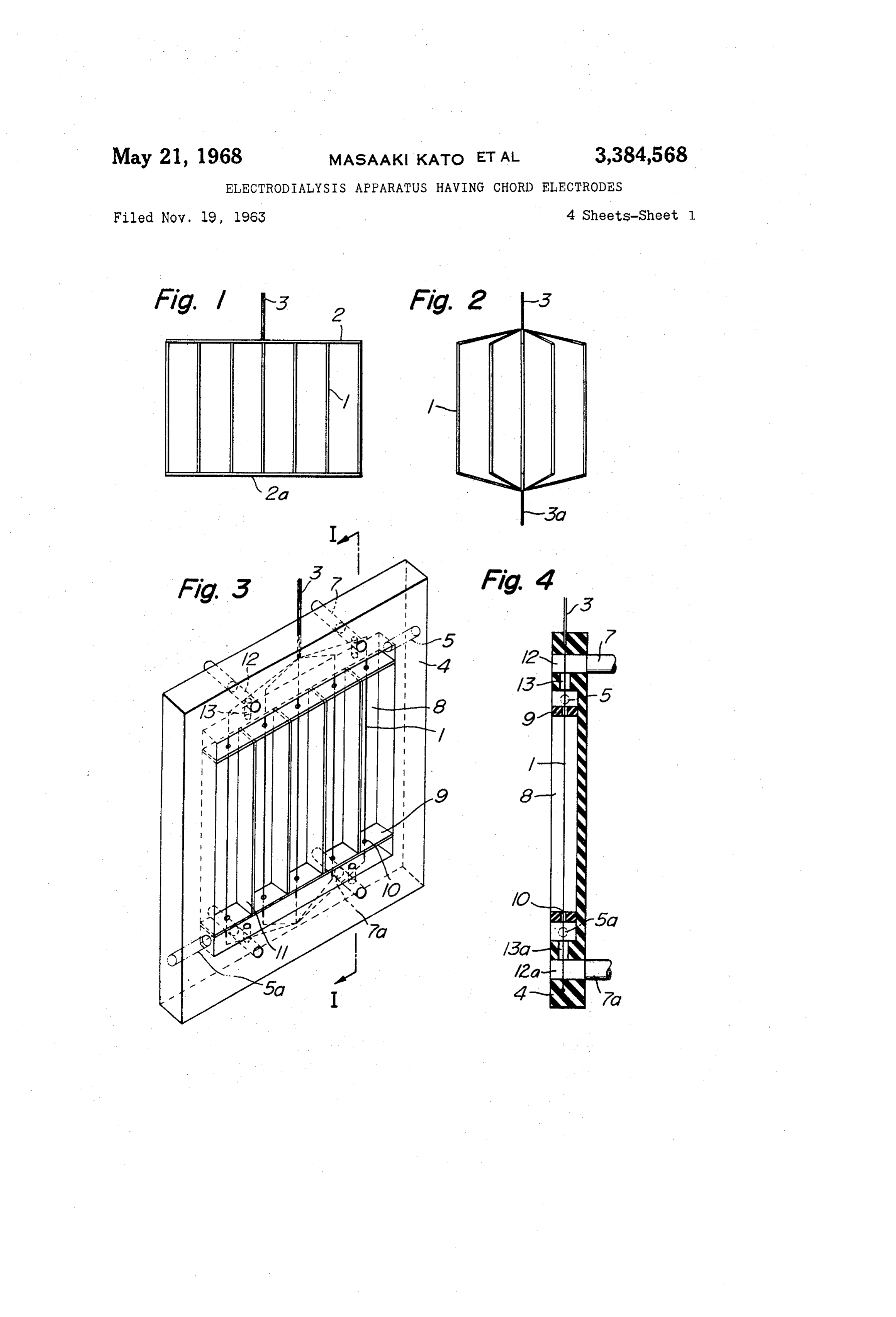
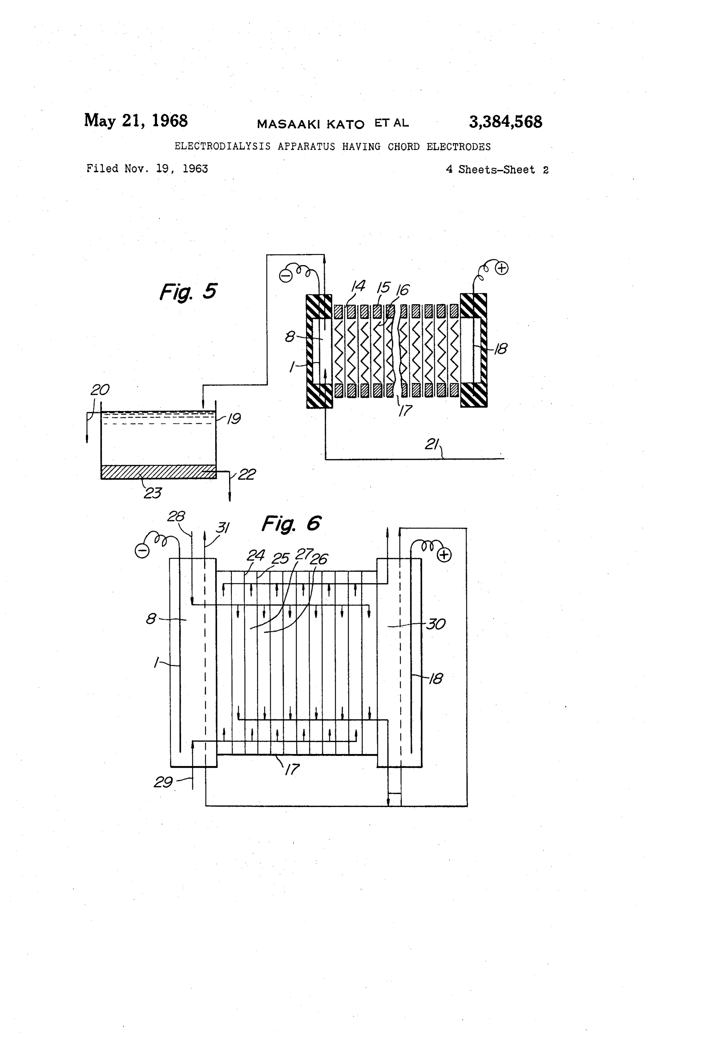
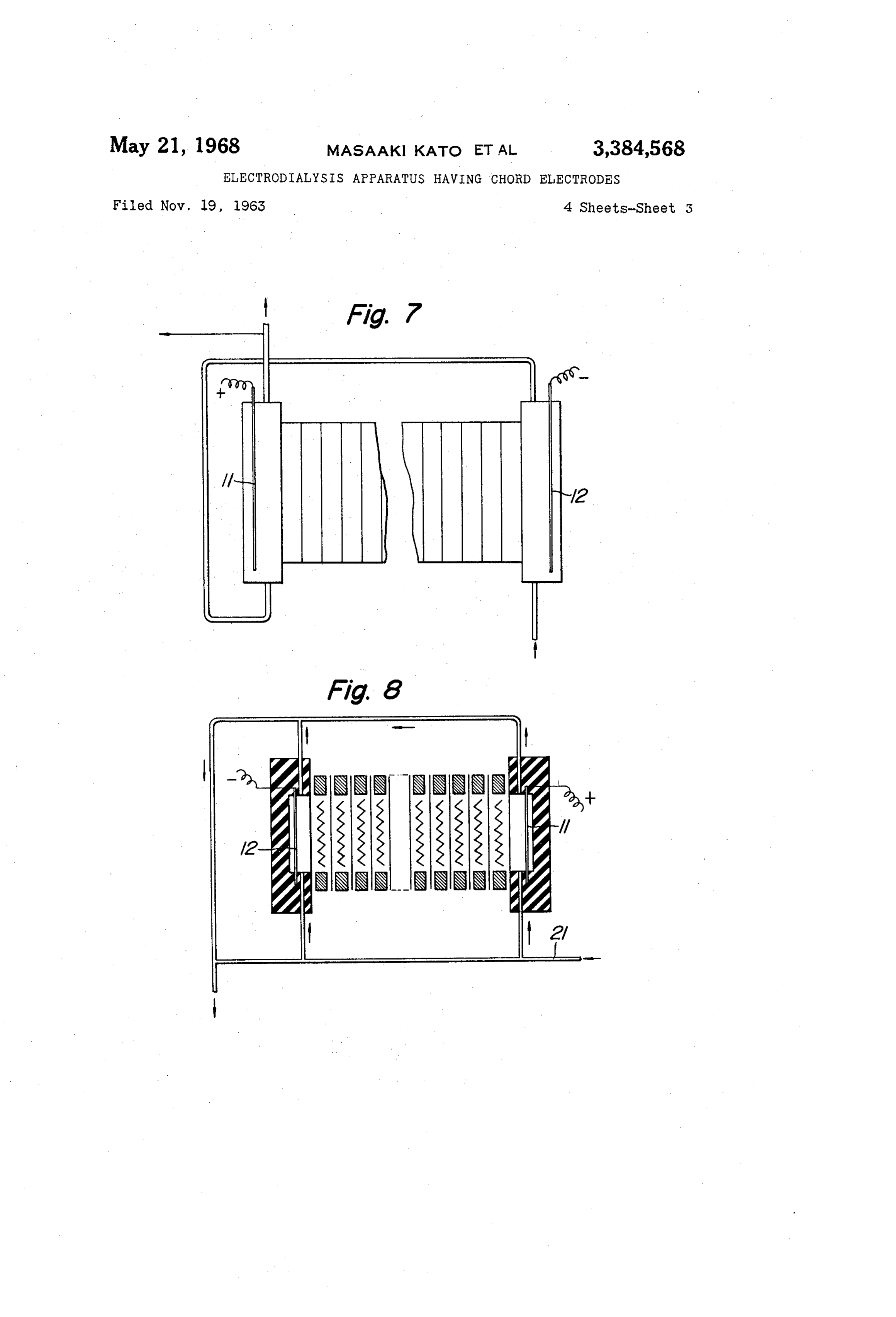
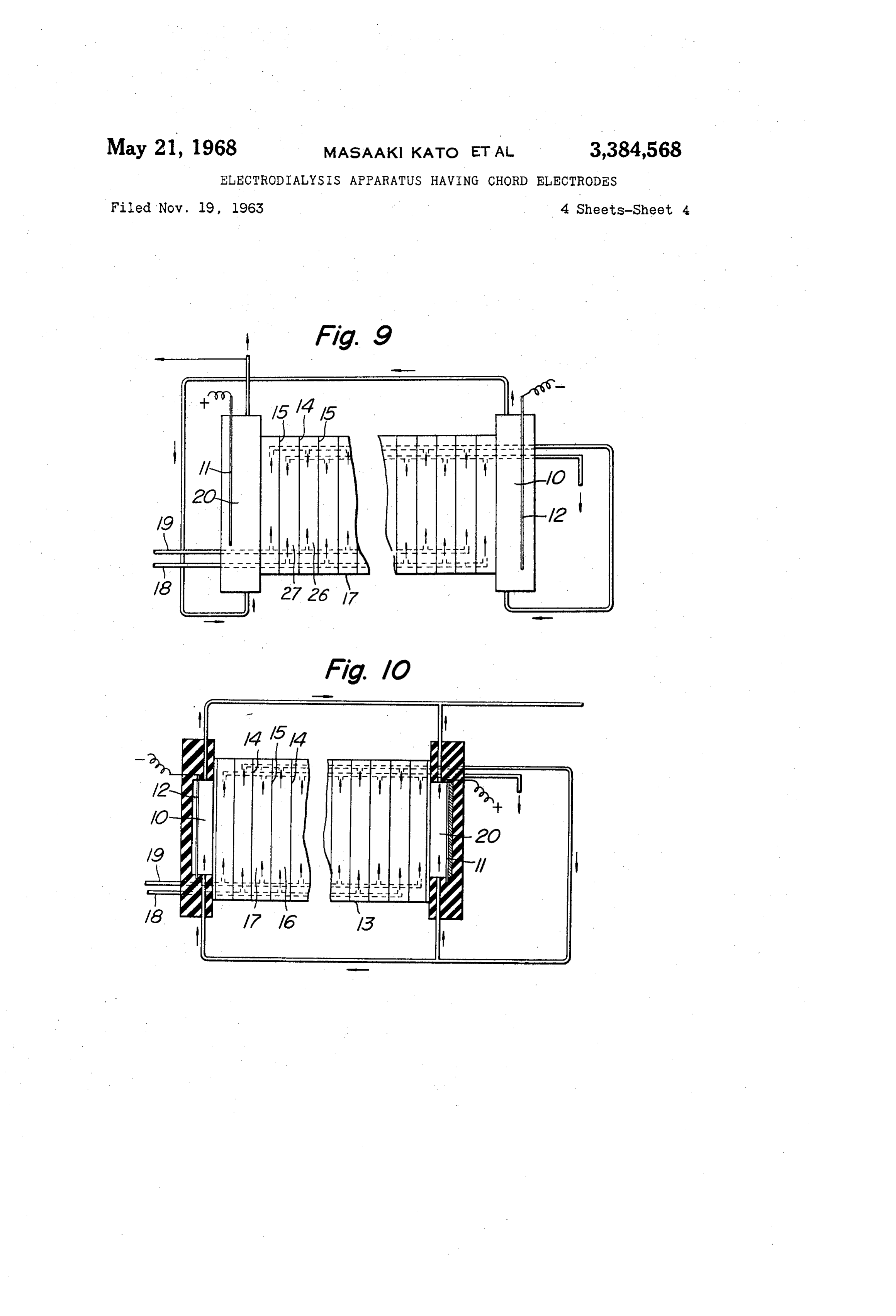
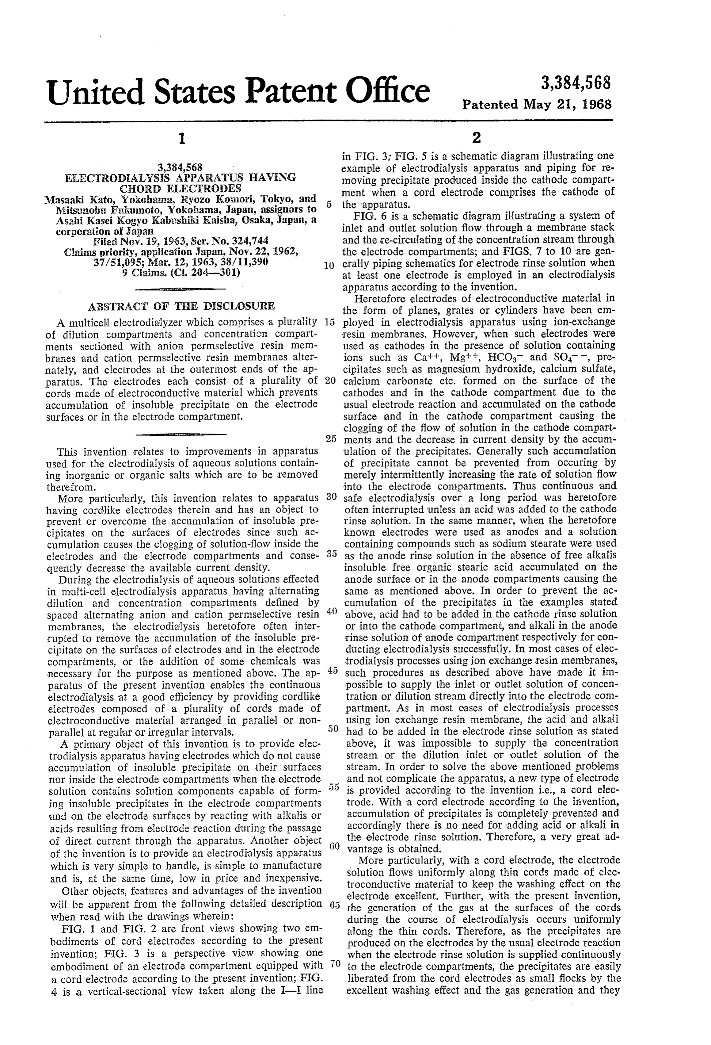
of the invention is to provide an electrodialysis apparatus More particularly, with a cord electrode, the electrode which is very simple to handle, is simple to manufacture solution flows uniformly along thin cords made of elec and is, at the same time, low in price and inexpensive. troconductive material to keep the washing effect on the Other objects, features and advantages of the invention will be apparent from the following detailed description electrode excellent. Further, with the present invention, the generation of the gas at the surfaces of the cords when read with the drawings wherein: during the course of electrodialysis occurs uniformly FIG. 1 and FIG. 2 are front views showing two em along the thin cords. Therefore, as the precipitates are bodiments of cord electrodes according to the present produced on the electrodes by the usual electrode reaction invention; FIG. 3 is a perspective view showing one when the electrode rinse solution is supplied continuously embodiment of an electrode compartment equipped with to the electrode compartments, the precipitates are easily a cord electrode according to the present invention; FIG. liberated from the cord electrodes as small flocks by the 4 is a vertical-sectional view taken along the I-I line excellent washing effect and the gas generation and they
Page 6
are removed from the electrode compartment along with other optional form. The cords can be arranged either in the rinse solution. Accordingly, no accumulation of pre parallel or non-parallel and need not necessarily be cipitates occurs on the electrodes or in the electrode com straight but can be curved.
partments. Therefore, continuous and steady operation is FIG. 2 is the front view showing another example of possible. These advantages occur only because of the use 5 an electrode in accordance with the present invention, in of the cord electrodes of the present invention. During which electrode plugs 3 and 3a are arranged at the upper electrodialysis using the electrodes of the present inven and lower parts.
tion particles of the precipitates liberated from the cords FIG. 3 shows an example of an electrode compartment are small in size and accordingly do not cause any restric in which a cord electrode is employed. Each of the cords 1 tion in the flow of electrode rinse solution since they do O passes through the center of one of a plurality of small not adhere to nor accumulate in the electrode compart holes E0 in rectifier plates 9 which is of an insulating ma ments or attached piping. By this action of preventing terial and operates as a rectifier for solution-flow and a accumulation, it is unnecessary to add acid into the cath concentrator for the generation of gas around the cords. ode compartment and alkali into the anode compartment Between adjacent cords 1 there is a spacer 11 made of as has been hitherto necessary to prevent formation of electric insulating material. The rectifying plate 9 and the precipitate in the case of electrode rinse solutions con spacer are employed to carry out more effectively a taining scale-forming components. Accordingly, the omis uniform flow of the electrode rinse solution around the sion of pumps, piping, tank. and auxiliary equipment or cord electrode to obtain a good washing effect on the other means for supplying acids and alkalis has made the operation and apparatus remarkably simple. Further, by cords 1. The cord electrode alone can operate completely without the rectifying plate 9, and the spacer 11, since the employing cord electrodes in electrodialysis apparatus use of cords as electrode and the arrangement of a plu having alternating dilution and concentration compart rality of cords longitudinally cause a good Washing effect ments with spaced anion and cation permeselective resin around the cords and the even generation of gas. Accord membranes therebetween, concentration streams and ingly, there is an easy liberation of the insoluble precipi dilution streams which passed through the membrane 25 tate formed on the surfaces of cords and inside the elec stacks can directly be supplied to the electrode compart trode compartments. However, by combining the rectify ments, as the electrode rinse stream. Accordingly, there is ing plates and spacers with the cords, economical electro a more economical use of water and the elimination of the dialysis is possible using a smaller quantity of electrode usually required parts such as piping, pumps, tanks etc. solutions. - for supplying electrode rinse solution separately. There is In FIG. 3, two rectifying plates 9 are set at the upper thus provided a simplified apparatus for performing eco and lower ends of the cord electrode. However, it is pos nomical electrodialysis which is easy to handle and oper sible to arrange a plurality of rectifying plates 9 and ate. Besides, by taking advantage of the fact that the spacers 10 at regular or irregular intervals so as to in precipitates are liberated without adhesion and accumu crease the velocity of a solution flow on the surface of lation and are continuously removed from the compart each cord and to concentrate the gas produced from the ments by flotation in the electrode rinse solution, when electrodes on the surface of the cord 1. Electrode rinse sea water is supplied to cathode compartments in elec solution is conducted, through inlet pipes 7a or 7 made trolysis apparatus in which the cord electrodes of the of electric insulating material to supply electrode rinse present invention are employed as the cathode, the precipi solution into the holes 12a or 12 passing through the tate of Mg(OH)2 is formed on the cathode and as soon as 40 frame 4 which are to be connected with the pipes 7a or 7, it grows slightly it can be liberated from the cord and dis and through holes 13a or 13 to compartment 8 enclosing charged from the compartment with the catholyte, and the space area around the cord . The rinse solution cir after being brought to a settling tank or reservoir, the culates around the cord 1 from bottom to top or from top precipitate of Mg(OH) is removed for use as a raw mate to bottom, and then discharged through holes 13 or 13a, rial for metallic magnesium and magnesia clinker. 12 or 12a and pipes 7 or 7a. This conduit system can be Referring now to FIG. 1, there is shown a plurality of replaced by pipes 5 and 5a.
cords 1 made of electroconductive material mechanically FIG. 4 is a vertical sectional view taken along the I-I and electrically connected at their upper and lower ends line in FIG. 3 (the reference characters are the same as to connecting rod 2 made of electroconductive material. those in FIG. 3).
An electrode plug 3 is connected to the connecting rod 2. Several examples of electrodialysis apparatus using The diameter of the cord 1 is preferably under 5 mm. anion exchange resin membranes and cation exchange With cords having diameters greater than 5 mm. the Eib resin membranes to define dilution and concentration eration effect of precipitates is lowered. The connecting. compartments therebetween and cord electrodes as cath rods are provided for the purpose of insuring the mechani ode or anode thereof are hereinafter explained. It should cal rigidity of the electrode structure for passing electric be noted that the apparatus of the present invention current from an external current source to the electrodes characterized by cord electrodes therein as well as the by means of the electrode plug. construction of the stack has enabled the economical reuse - The liberation effect is especially effective when the of the feed solution without any complication of the ap shortest distance between the mutually adjacent cords 1 paratus or its operation as well as smooth electrodialysis (the intervals between the two cords) is 0.5-50 mm. 60 over long periods. This was first realized by the good When the distance is less than 0.5 mm., a mutual contact liberation-effect of the precipitate on the electrode as a of the cords 1 can easily occur, lowering the liberation result of electrode reaction. In this apparatus a part or effect of precipitates. On the other hand, when the sepa all of outlet solution from concentration or dilution com ration is greater than 50 mm., current density concen partments or raw sea water and raw-brackish water from trates locally, producing unfavorable electrodialysis. Fur 65 a separate source is conducted into both the cathode and thermore the apparatus becomes large, a disadvantage anode compartments of one electrode compartment to from the economic point of view. the other in series or in parallel as the electrode rinse The materials used for the cords 1 are metals such as solutions.
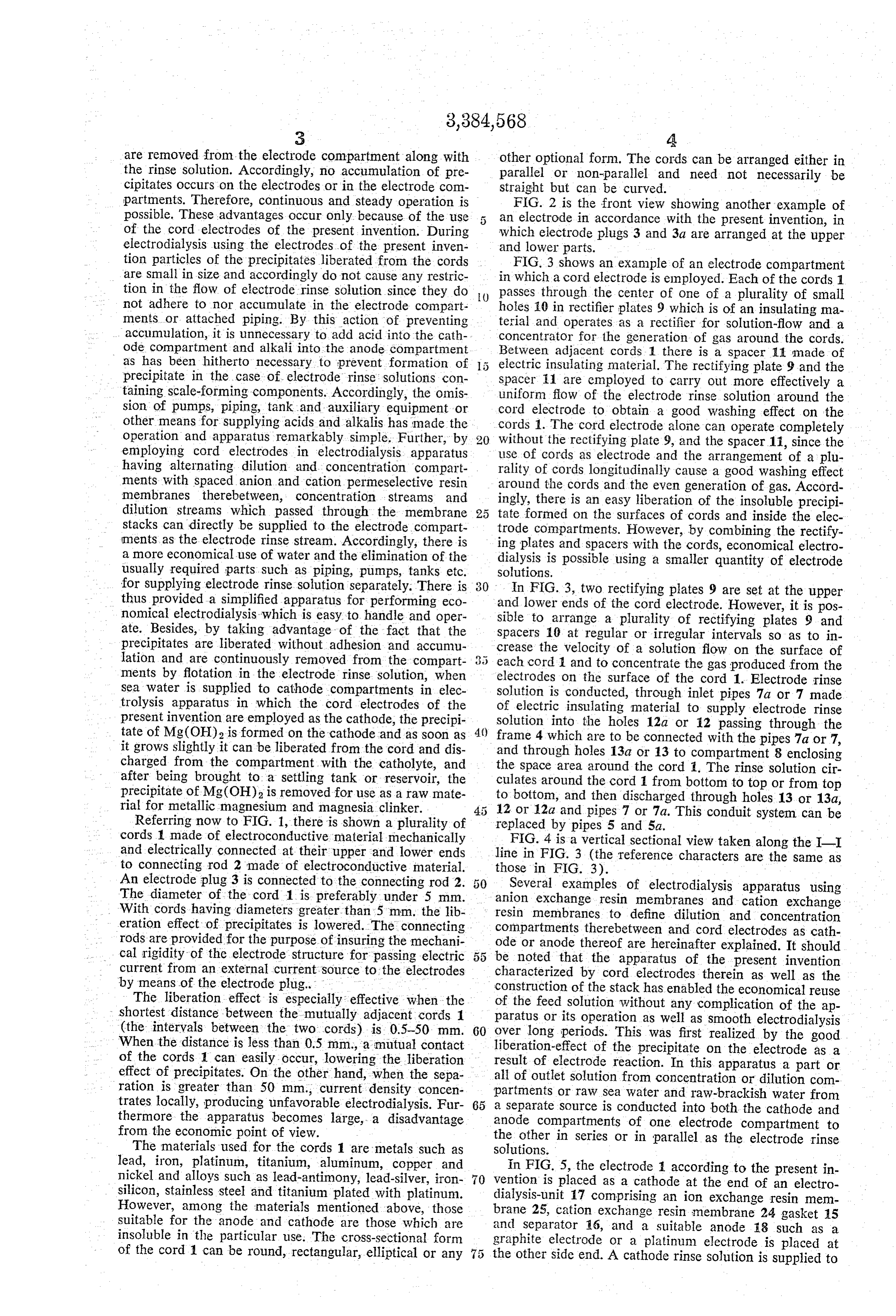
lead, iron, platinum, titanium, aluminum, copper and In FIG. 5, the electrode 1 according to the present in nickel and alloys such as lead-antimony, lead-silver, iron vention is placed as a cathode at the end of an electro silicon, stainless steel and titanium plated with platinum. dialysis-unit 17 comprising an ion exchange resin mem However, among the materials mentioned above, those brane 25, cation exchange resin membrane 24 gasket 15 suitable for the anode and cathode are those which are and Separator 6, and a suitable anode 8 such as a insoluble in the particular use. The cross-sectional form graphite electrode or a platinum electrode is placed at of the cord 1 can be round, rectangular, elliptical or any the other side end. A cathode rinse solution is supplied to
Page 7
area 8, the cathode compartment and electrodialysis is In an electrodialysis of a solution containing organic carried out by passing direct current between cathode 1 matter, a fouling of the membranes, an increase in the and anode 18. Precipitate, for example, Mg(OH)2 which resistance, a prevention of solution-flow inside the con is produced in the cathode compartment flocks and is centration compartments resulting in lowering the effi brought out of the compartment by the outlet stream of ciency of electrodialysis are likely to occur. It is known cathode rinse solution. The flock is precipitated in a suit that the polarity reversal process is effective to overcome able settling pool 19 and top solution flows of through these problems.
overflow-pipe 20. Percipitate is drawn off via conduit 22. In the usual electrodialysis apparatuses, the device of When electrodialyzing a solution containing compo polarity reversal as described in U.S. Patent No. nents such as sodium stearate which produce useful 10 2,863,813, accompanies the complication of apparatuses precipitate in the anode compartments, the cord electrode and handling, namely, the simultaneous interchanging of is used as the anode and the procedure as mentioned the electrode rinse solutions and of the acid feed piping above can be carried out with the abovementioned metals to the cathode rinse solutions for pH adjustment. The as the cathode and extracting the anode solution contain polarity reversal can be carried out without any com ing precipitates. 15 plicated operation by the electrodialysis apparatus of the FIG. 6 is a schematic sectional view showing one ex present invention using a cord electrode. In the appara ample of an electrodialysis apparatus of the present in tus shown in FIGS. 7, 8, 9 and 10, the periodic or cyclic vention wherein the cord electrode is applied to cathode 1. interchange of dilution stream and concentration stream In FIG. 6, as in FIG. 5, anion exchange resin membranes alone is necessary to carry out the periodic or cyclic re 25 and cation exchange resin membranes 24 are assembled 20 versal of the direction of the direct current, without ac in unit 17 defining concentration compartment 26 and companying any other interchanging of electrode rinse dilution compartment 27. The concentration stream after solution or the adding of chemicals for pH adjustment to passing each concentration compartment 26 is again con the electrode rinse solutions.
ducted to the anode compartments 30 and then cathode These features and merits of the instant invention will compartment 8 in series. 25 be appreciated by the following examples. FIG. 7 and FIG. 8 show a flow of an electrode rinse EXAMPLE 1. solution which can be employed when electrodes such as are shown in FIG. 1 and FIG. 2 are used for the anodes The example shows an experiment on obtaining mag and cathodes of an electrodialysis apparatus. FIG. 7 nesium hydroxide as a by-product from the concentration shows an example of passing an electrode solution in 30 of sea water by means of electrodialysis apparatus of this Series from the cathode compartment to the anode com invention. The unit included 250 anion membranes, 250 partments or vice versa. Cord electrodes are used as dilution compartments, 250 cation membranes, and 249 anode 18 and cathode 1. The solution conducted to the concentration compartments. The electrode was construct electrode compartments may be either the outlet stream 35 ed as shown in FIG. 3, and included round stainless steel from either concentration or dilution compartment, raw cords having a diameter of 1.5 mm. as the cathode and sea water or raw brackish water from another source a graphite electrode as the anode, all arranged as shown without adjusting pH. FIG. 8 shows how a solution from in FIG. 6. The entire unit passed 400 amperes of direct an outside source is used as an electrode rinse solution current. Into the cathode compartment sea water of neu and is conducted in parallel. tral pH was supplied at the flow rate of 20 liters a minute. FIG. 9 illustrates the situation in which cord electrodes 4) Sea water with a 0.536 N chloride ion concentration was are used as both the anode and the cathode. A plurality supplied to dilution compartment 27 at a flow rate of 600 of dilution compartments 27 and concentration compart liters a minute, and concentrated sea water with a 3.5 N ments 26 are formed with spaced alternate cation ex chloride ion concentration was circulated in the concen change resin membranes 24 and anion exchange resin tration compartment at a rate of 84.4 liters a minute. membranes 25 respectively therebetween with cation ex Magnesium hydroxide was continuously obtained at the change resin membrane 24 as the diaphragm on the cath rate of 391. gr./hr. as a by-product of the electrodialysis ode side and anion exchange resin membrane 25 as the in addition to concentrated sea water having a 3.5 chlo diaphragm on the anode side. rine ion concentration and diluted sea water having a 0.30 The anode compartment 30 and the anode compart N chlorine ion concentration. Further, no accumulation ment 8 are constructed as shown in FIG. 3. Dilution solu 50 of Scale was found in the cathode compartment and cath tion is supplied through inlet pipe 19 and concentration Ode surface after 7 days of continuous operation. solution is supplied through inlet pipe 20 to each compart ment 27 and 26 respectively in a stack 17. Concentration EXAMPLE 2 solution discharged from stack 17 through concentration An electrodialysis apparatus was prepared as shown in compartments 26 directly flows into cathode compart 5 5 FIG. 3 comprising a stack consisting of 100 pairs of cation ments 8 and then directly to anode compartments 30 in eXchange resin membranes and anion exchange resin series and is discharged after passing through the com membranes forming 100 dilution compartments and 99 partments. The outlet stream from cathode or anode com concentration compartments each of which had an effec partment may be circulated from anode compartment 30 tive electrodialysis area of 8.6 dim.2 by using cathode and to cathode compartment 8 in series. 60 anode compartments as shown in FIG. 3 and including FIG. 10 is a schematic diagram illustrating an example electrodes consisting of platinum plated titanium round in which a cord electrode such as shown in FIGS. 1 and 2 cords with a diameter of 1 mm. Sea water of neutral pH is the cathode 1 and a graphite electrode is the anode 18.
All of the concentrating solution is used as electrode rinse with a concentration of 35,000 p.p.m. was circulated into solution. Stack 17 is made by alternately arranging a plu 65 the dilution compartment 27 at a flow rate of 100 liters a minute and into concentration compartment 26 at a flow rality of concentration compartment 26 and dilution com rate of 15 liters a minute. When the outlet stream from partments 27. Inlet solution for the concentration com partment is supplied through inlet pipe 20 and inlet solu the concentration compartment 26 was first supplied to the cathode compartment 8 and then the anode compart tion for the dilution compartment is supplied through ment 30 in series as shown in FIGURE 9 and when inlet pipe 19 into each compartment. The apparatus is so 70 formed that the concentration stream which passed each operated with a direct current of 30 amperes, sea water concentration compartment 26 in stack 17, is divided into of 34,000 p.p.m. was continuously obtained from dilution two portions, one portion passing through space area compartment 27 at a current efficiency of 95%. A con 30 of the anode compartment, the other portion passing tinuous run was made for 10 days under said conditions through space area 10 of cathode compartment. 75 With no accumulation observed in cathode compartment
Page 8
8 and anode compartment 36 and the electrodialysis was was reduced from 1100 p.p.m. to 980 p.p.m. The con carried out smoothly. tinuous electrodialysis under the condition as mentioned EXAMPLE 3 above for 10 days was smoothly carried out.
The electrodialysis unit of Example 2, when continu 5 What is claimed is:
1. A multicell electrodialysis apparatus comprising a ously operated on the same solution as in Example 2 for plurality of alternate cation permselective resin mem 10 days under the same conditions, as in the Example 2 branes and anion permselective resin membranes forming by reversing the flow of the electrode solution, e.g., from alternate concentration compartments and dilution com anode compartment 30 to cathode compartments 8. No partments, an anode electrode compartment at one end accumulation of the precipitates was found in cathode of the apparatus and a cathode electrode compartment at compartment and anode compartment. - the other end of the apparatus, a cord electrode fixed in EXAMPLE 4 at least one of said electrode compartments comprising a The electrodialysis unit of Example 2, was operated on plurality of vertically extending cords of electroconductive diluted sea water with a concentration of solute of 1100 material, connecting rods of electroconductive material p.p.m. Supplied to the dilution compariments 27 at flow fixedly attached to the upper ends and the lower ends of rate of 100 liters a minute and sea water of neutral pH Said cords to Supply electric current to the cords and to Was Supplied to the concentration compartments 25 at provide mechanical rigidity for the electrode, and an flow rate of 15 liters a minute while the entire unit passed electrode plug of electroconductive material attached to a direct of current of 6 amperes. The salinity of the 20 at least one of said connecting rods to supply electric cur rent from an external current source to the connecting diluted sea water was reduced from 1100 p.p.m. to 900 rods, an inlet for electrode rines solution at one of the p.p.m. at a current efficiency of 90%. A continuous run ends of the electrode compartments and an outlet for was made for 10 days under these conditions and no ac electrode rinse solution at the other of the ends of the Cumulation was observed in cathode compartment 8 and electrode compartments.
anode compartment 30, and a smooth electrodialysis was 25 2. A multicell electrodialysis apparatus as claimed in
claim 1, comprising supply and exhaust conduits disposed
EXAMPLE 5 at the upper and lower parts of the dilution and concen tration compartments for carrying diluting and concen
An electrodialysis unit had 110 pairs of anion and cat trating ion permselective resin membranes defining 110 dilution 30 groups solutions, the exhaust conduit from one of the of compartments passing solution upwardly compartments and 109 concentration compartments there through one electrode compartment from the lower end between as shown in FIG. 10, each of which had an effec to the upper end and then passing solution upwardly tive electrodialysis area of 8.6 dim.2. The electrodes em through the other electrode compartment in series from ployee were as is shown in FIG. 2 and included round the lower end to the upper end for supplying to said cords made of stainless steel having a diameter of 1 mm. electrode compartments electrode rinse Solution. as the cathode and a graphite electrode as the anode. 3. A multicell electrodialysis apparatus as claimed in into the dilution compartments, diluted sea water with a concentration of 1100 p.p.m. was supplied at flow rate claim 1, comprising supply and exhaust conduits disposed of 150 liters a minute and into the concentration compart tration upper at the and lower parts of the dilution and concen compartments for carrying diluting and concen ments, neutral Sea Water was supplied at flow rate of 15 40 trating solutions, the conduit from one of the group of liters a minute. One liter a minute of the outlet solution compartments being divided into two conduis each of from the concentration compartment was supplied to which passes solution upwardly through an electrode com anode compartment and the remainder to cathode com partment in parallel from the lower end to the upper end partment. When the entire unit operated with a direct cur to supply to said electrode compartment electrode rinse rent of 6 amperes at a current efficiency of 90%, the solution.
salinity was reduced from 1100 p.p.m. to 950 p.p.m. 4. A multicell electrodialysis apparatus as claimed in This electrodialysis unit was run for 10 days continu claim 1 including a source of electrode rinse solution and ously and a smooth electrodialysis was obtained without a supply conduit for the electrode rinse solution, said accumulation of insoluble precipitate in cathode compart supply conduit passing rinse solution to the inlet of one ments. of the said electrode compartments and then passing On the other hand, when the apparatus constructed as 50 solution through the other of said electrode compartments mentioned above with a plate made of stainless steel as upwardly in series from the lower end to the upper end. the cathode was operated with Sea water as mentioned 5. A multicell electrodialysis apparatus as claimed in above, an accumulation of magnesium hydroxide in cath claim 4, wherein said supply conduit for the electrode ode compartment was observed after 3 hours of electro rinse solution is divided into two conduits each of which dialysis under the same condition as mentioned above, upwardly passes solution through the electrode compart resulting in the decrease in current density and clogging ments in parallel from the lower end to the upper end. of the solution. Thus the electrodialysis was completely 6. A multicell electrodialysis apparatus as claimed in impossible. claim 1, comprising supply and exhaust conduits disposed
EXAMPLE 6
60 at the upper and lower parts of the dilution and concen
An electrodialysis unit constructed, as described in tration compartments for carrying diluting and concen Example 2 but with 200 pairs of anion and cation perm trating solutions, the exhaust conduit from one of said selective resin membranes, was provided with pipes which groups of compartments passes solution upwardly through circulated a part of the outlets stream from the con one electrode compartment from the lower end to the centration compartments into electrode compartments as 65 upper end and then passes solution upwardly through the electrode solutions. Diluted sea water of 1100 p.p.m. was other electrode compartment in series from the lower end supplied to dilution compartment 17 at flow rate of 300 to the upper end for supplying to the electrode compart liters a minute, and sea-water of neutral pH to concen ments electrode solution to permit polarity reversal of tration compartment as a flow rate of 30 liter a minute in said electrodes while exchanging flow of diluting solution circulation, and 1 liter a minute of the outlet stream and concentrating solution.
from the concentration compartment 26 was Supplied to 7. A multicell electrodialysis apparatus as claimed in the anode compartment, 15 liters a minute to the cathode claim 1, comprising supply and exhaust conduits disposed compartment and the remainder discarded. When the at the upper and lower parts of the dilution and concen entire unit operated with a direct current of 6 amperes tration compartments for carrying diluting and concen at a current efficiency of 90%, the salinity of the sea-water 75 trating solutions, the exhaust conduit from one of said
Page 9
groups of compartments being divided into two conduits 9. A multicell electrodialysis apparatus as claimed in each of which upwardly passes solution through an elec claim 8, wherein said conduit for the electrode solution trode compartment in parallel from the lower end to the is divided into two conduits each of which upwardly upper end to permit polarity reversal of said electrodes passes solution through the electrode compartments in while exchanging flow of diluting solution and concen parallel from the lower end to the upper end to permit trating solution. polarity reversal of the electrodes while exchanging flow 8. A multicell electrodialysis apparatus as claimed in of diluting solution and concentrating solution. claim 1, including an external source of electrode rinse References Cited solution and a conduit for the electrode solution wherein said conduit passes solution upwardly through one elec IO UNITED STATES PATENTS trode compartment from the lower end to the upper end 3,135,674 6/1964 Ruetschi------------ 204-301 and then passes solution upwardly through the other elec 3,192,143 6/1965 Roe et al. ---------- 204-301 trode compartment in series from the lower end to the upper end to permit polarity reversal of the electrodes JOHN H. MACK, Primary Examiner. while exchanging flow of diluting solution and concen 15 trating solution. E. Z.AGARELLA, Assistant Examiner.
Provenance
- Collection
- Cited prior art
- Original PDF
- patentimages.storage.googleapis.com →
- Filed
- 1963-11-19
- Pages
- 9
- Method
- pdftotext (the PDF's own text layer) + pdftoppm 300dpi page scans
- Source
- Google Patents bibliographic record
- Granted
- 1968-05-21
- Inventors
- Kato Masaaki; Komori Ryozo; Fukumoto Mitsunobu; Asahi Chemical Industry Co Ltd
- Transcribed from
- patentimages.storage.googleapis.com →