patent · US4133660
Adsorber for removing pollutants from gases having uniform adsorption capability
9 January 1979
Page 1 — bibliographic record
United States Patent (19) 11) 4,133,660 Steiner 7. 45) Jan. 9, 1979
54 ADSORBER FORREMOVINGPOLLUTANTS FOREIGN PATENT DOCUMENTS
FROM GASES HAVING UNIFORM
ADSORPTION CAPABILITY 2239827 2/1974 Fed. Rep. of Germany ............. 55/479 Primary Examiner-Bernard Nozick (75. Inventor: Peter Steiner, Edison, N.J. Attorney, Agent, or Firm-Marvin A. Naigur; Warren B. Kice 73) Assignee: Foster Wheeler Energy Corporation,
Livingston, N.J. 57 ABSTRACT
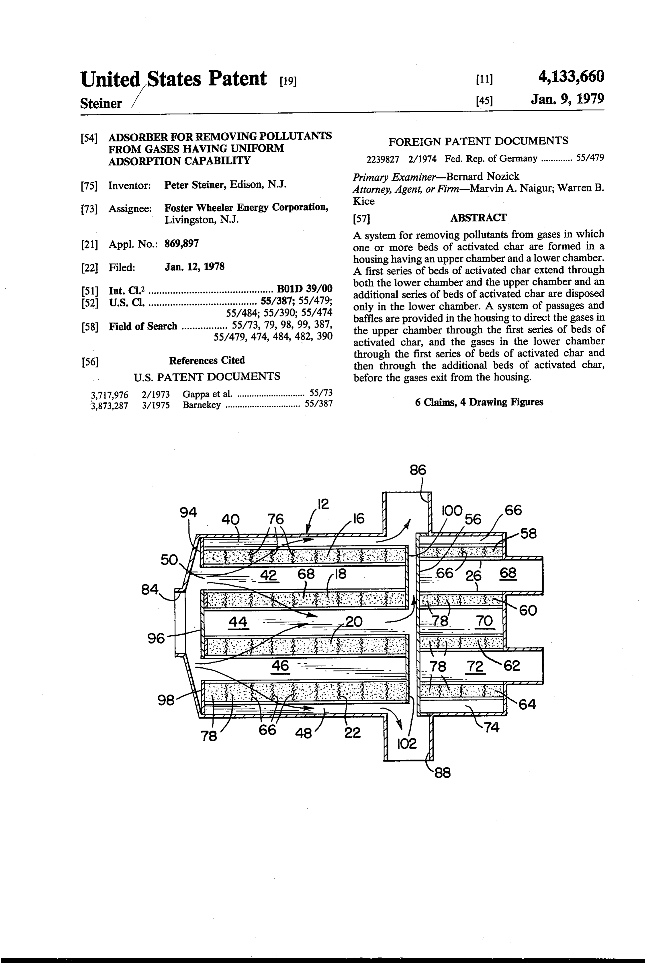
A system for removing pollutants from gases in which (21) Appl. No.: 869,897 one or more beds of activated char are formed in a housing having an upper chamber and a lower chamber.
(22 Filed: Jan. 12, 1978 A first series of beds of activated char extend through 51) Int. Cl............................................... B01D 39/00 both the lower chamber and the upper chamber and an additional series of beds of activated char are disposed 52 U.S. C. ........................................ 55/387;55/479; only in the lower chamber. A system of passages and 55/484;55/390; 55/474 baffles are provided in the housing to direct the gases in 58 Field of Search ................. 55/73, 79,98, 99,387, the upper chamber through the first series of beds of 55/479, 474, 484, 482,390 activated char, and the gases in the lower chamber 56) References Cited through the first series of beds of activated char and then through the additional beds of activated char,
3,717,976 2/1973 Gappa et al. ............................ 55/73 6 Claims, 4 Drawing Figures 3,873,287 3/1975 Barnekey ............................... 55/387
per Zz-z-z Al Az-z-z-z-z-ZA-z-z-z-z
SEA
Page 2
Drawing sheet — no readable text.
Page 3
It is a more specific object of the present invention to
ADSORBER FOR REMOVING POLLUTANTS provide an adsorber of the above type in which a plural FROMGASES HAVING UNIFORMADSORPTION ity of beds of activated char are provided in the upper CAPABILITY portion of the adsorber and a plurality of additional beds of activated charare provided in the lower portion
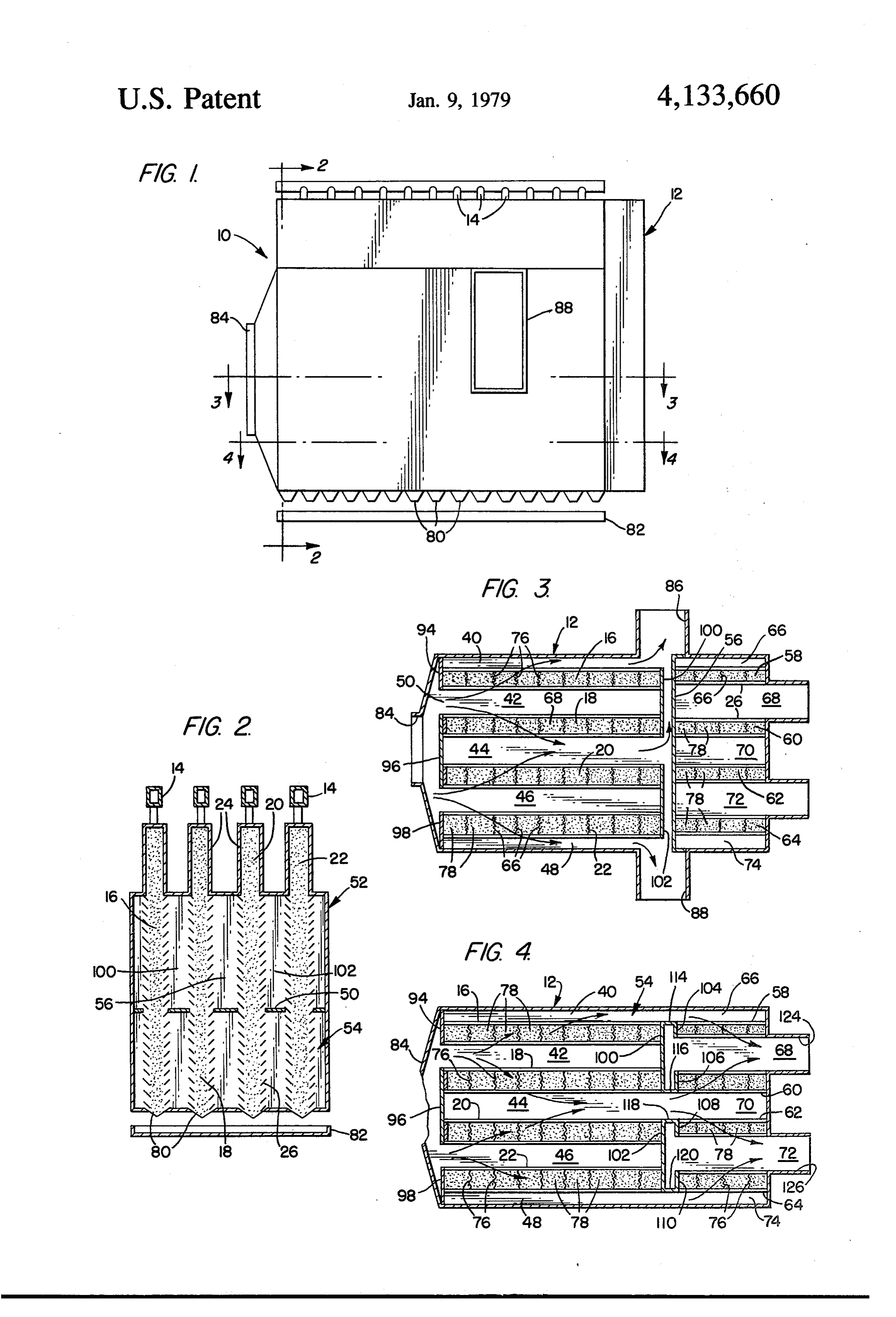
BACKGROUND OF THE INVENTION of the adsorber in order to insure a uniform adsorption This invention relates to the removal of pollutants of the pollutants from all the gases entering the adsorber from gases and, more particularly, to an adsorber sys and to increase the adsorption capacity. tem in which pollutant laden gases are passed through 10 Towards the fulfillment of these and other objects, columns of activated char to adsorb the sulfur oxides the system of the present invention includes a housing from the gases into the char pellets. having inlet means for receiving the pollutant-laden The technique of adsorption to remove sulfur oxides gases and outlet means for discharging the gases. An from pollutant-laden gases, such as flue gases from a upper chamber and a lower chamber are defined in the housing, and a first series of beds of activated char fossil fuel boiler, is well known. According to this basic extend through the upper chamber and the lower cham process, an adsorber is provided which receives the 15 ber, gases and includes a bed of activated char located in the are defined in the lowerseries while an additional of beds of activated char chamber. The gases are di path of the gases. As a result, the SO2, oxygen and rected from the inlet means, across the first series of water vapor in the gases come into contact with, and are adsorbed by, the char pellets. The SO2 in the gases 20 beds of activated char in the upper chamber and to the outlet means. In the lower chamber the gases are di is oxidized to SO3 and subsequently catalytically con rected from the inlet means across the first series of beds verted to sulfuric acid which is held in the interior pore of activated char, across the additional series of beds of system of each char pellet. The substantially pollutant activated char and to the outlet means. free gases are then passed to a stack, or the like, for exhaustion into the atmosphere. 25 BRIEF DESCRIPTION OF THE DRAWINGS The adsorber usually contains one or more vertical The above brief description, as well as further ob beds of activated char which moves downwardly in jects, features, and advantages, of the present invention mass flow while adsorbing the pollutants from the will be more fully appreciated by reference to the fol gases. The upper portion of the char bed is continuously lowing detailed description of a presently preferred but replenished while the saturated char is collected at the 30 nonetheless illustrative embodiment in accordance with bottom and sent by conveyors to other sections of the the present invention, when taken in connection with system. For example, the saturated char can be sent to a the accompanying drawings wherein:
regenerator for regenerating the saturated char by ther FIG. 1 is a side elevational view of the housing of the mal or wet regeneration to reverse the reactions taking system of the present invention; and place in the adsorber and produce a concentrated steam 35 FIGS. 2, 3 and 4 are cross sectional views taken along of SO2, H2O, CO2, and N2. The stream of SO2 can then the lines 2-2, 3-3 and 4-4, respectively of FIG. 1. be further treated to produce relatively pure sulfur. DESCRIPTION OF THE PREFERRED In these type of arrangements it has been discovered EMBODIMENT that due to the length of the vertical beds, less adsorp tion of the pollutants from the gases passing through the The adsorber of the present invention is shown by the lower portion of the adsorber housing is achieved when reference number 10 in FIGS. 1 and 2 and includes a compared to the gases passing through the upper por housing 12 of suitable refractory material, or the like, tion of the housing. This is due to the fact that the char having a plurality of feeders 14 disposed on the upper in the lower portion of the housing is less active than portion thereof for receiving activated char from a that in the upper, since the former is more saturated 45 source (not shown) and directing same into the upper with pollutants by virtue of its increased exposure to the portions of a plurality of vertical columns 16, 18, 20, and gases as it passes downwardly in the housing. As a 22 (FIG. 2) located within the housing. The upper por result, it is impossible to achieve a constant average tions of the side walls of the columns 16-22 are defined degree of adsorption of the pollutants and, in addition, a by surge sections 24 (FIG. 2) formed in the upper por less than optimum system efficiency is achieved. 50 tion of the housing 12, and the remaining portions of the U.S. Pat. No. 3,717,976, of which the present inven side walls are formed by a plurality of parallel louvers tor is a co-inventor, teaches a process in which the gases 26. The louvers 26 are sized and placed at optimum inlet in the lower part of the adsorber are passed through an and outlet angles to maintain a bed of char therein yet additional bed of activated char to remove additional permit the flow of gases therethrough, as will be de pollutants therefrom. However, this method is limited 55 scribed in detail later.
to the use of only one bed of char extending through the As shown in FIG. 3, the columns 16 and 22 are upper and lower portions of the adsorber and one addi spaced slightly from the corresponding side walls of the tional bed of char in the lower portion of the adsorber. housing 12, and each of the columns 16, 18, 20, and 22 As a result, the adsorption capacity of the adsorber is extends in a spaced, parallel relationship. As a result, a severely limited. passage 40 is defined between the column 16 and adja SUMMARY OF THE INVENTION cent side wall of the housing 12, a passage 42 is defined between the column 18 and the column 16, a passage 44
It is therefore an object of the present invention to is defined between the column 20 and the column 18, a provide an adsorber for adsorbing pollutants from gases passage 46 is defined between the column 22 and the in which a uniform adsorption efficiency is achieved. 65 column 20, and a passage 48 is defined between the It is a further object of the present invention to pro column 22 and the adjacent side wall of the housing 12. vide an adsorber of the above type which enjoys a rela As better shown in FIG. 2, a horizontal partition 50 is tively high adsorption capacity. provided in the housing 12 to divide a portion of the
Page 4
latter into an upper chamber 52 and a lower chamber 54. Also, as shown in FIG. 4, in the lower chamber 54 54. The partition 50 extends from the front end wall of a plurality of partition 104,106, 108, and 110 are located the housing 12 to a vertical wall 56 (FIGS. 2 and 3) immediately below the wall 56 and extend over the end located adjacent the columns 16-22 and extending from of the columns 58, 60, 62 and 64, respectively. Also, in the upper portion of the housing to the partition 50. 5 the lower chamber 54, a partition 114 extends across the As better shown in FIG. 3 an additional series of space between the columns 16 and 58, a partition 116 vertical columns 58, 60, 62, and 64 are located within extends across the space between the columns 20 and 62 the housing 12 and extend between the wall 56 and the and a partition 120 extends across the space between the rear wall of the housing. The upper portions of the side columns 22 and 64.
walls of the columns 58-64 are defined by additional 10 A pair of outlets 124 and 126 are formed in the hous surge sections 24 formed in the upper portion of the ing 12 in communication with the passages 68 and 72 in housing 12, and the remaining portions of the side walls the lower chamber 54. As a result of the above arrange are formed by a plurality of parallel louvers 26, as dis ment of inlets, outlets, passages and partitions, gas flow cussed above. in the lower chamber 54 is shown by the flow arrows in The columns 58 and 64 are spaced slightly from the 15 FIG. 4 and will be described in detail later. corresponding side walls of the housing 12, and each of In operation, activated char is continuously supplied the columns 58, 60, 62, and 64 extend in a spaced, paral to the columns 16-22 and 58-64 from the feeders 14 lel relationship. As a result a passage 66 is defined be where passes downwardly through the entire length of tween the column 58 and adjacent side wall of the hous the columns before exiting via the outlets 80. A portion ing 12, a passage 68 is defined between the column 60 20 of the pollutant-laden gases entering the inlet 84 of the and the column 58, a passage 70 is defined between the housing 12 pass into the upper chamber 52 where the column 62 and the column 60, a passage 72 is defined partitions 94-102 direct the gases into the passages 42 between the column 64 and the column 62, a passage 74 and 46, across the columns 16-22 of activated char, and is defined between the column 64 and the adjacent side to the passages 40, 44 and 48 before they impinge wall of the housing 12. 25 against the vertical wall 56 and are directed to the out A plurality of sheets 76 of a mesh-like material are lets 86 and 88, as shown by the flow arrows in FIG. 3. provided at spaced intervals along each column 16-22 As a result of passing across the columns 16-22 of acti and 58-64 to subdivide each of the columns into a plu vated char, the SO2 in the gases is adsorbed by the char rality of beds 78, each of which receives the activated in the manner discussed above.
char from a corresponding distributor 14. A char outlet 30 The remaining portion of the gases entering the hous 80 (FIGS. 1 and 2) is associated with each bed 78 and ing 12 pass into the lower chamber 54 where they are discharges the char into a collection trough 82 for fur directed in the same manner as discussed above until ther treatment, such as the regeneration step described they leave the outlet ends of the passages 40, 44, and 48. above. At this point they pass into the passages 66, 70, and 74 As a result of the foregoing, the char is continuously 35 in the rear portion of the housing as shown by the flow introduced into the columns 16-22 and 58-64 where it arrows in FIG. 4 from which they are directed across passes downwardly before discharging from the outlets the columns 58-64 of activated char before exiting from 80 and into the trough 82. the housing 12 via the passages 68 and 72 and the outlets An inlet 84 for pollutant-laden gases from a fossil fuel 124 and 126.
boiler, or the like, is formed in the housing 12 at one end 40 As a result, the gases passing through the lower thereof and communicates with both the upper chamber chamber 54 of the housing 12, are subjected to an addi 52 and the lower chamber 54. Two outlets 86 and 88 are tional adsorption by the char in the columns 58-64. This formed in the side walls of the housing 12 adjacent the is to compensate for the reduction in adsorption that vertical wall 56. As shown in FIG. 3 the columns 16-22 takes place in the lower portions of the columns 16-22 are spaced inwardly from the front end wall of the 45 due to the fact that the char in the latter portions is less housing 12 and from the wall 56 to permit passage of the active by virtue of being continuously contacted by gases in the upper chamber 52 from the inlet 84 through gases during its movement downwardly from the upper the various passages 40-48, and from the latter to the portions of the columns to the lower portions. outlets 86 and 88, as will be decribed in detail later. The substantially pollutant-free gases exiting from the As also shown in FIG. 3, a vertical partition 94 is 50 outlets 86, 88, 124 and 126 can then be passed to a stack, formed in the housing 12 and extends across the end of or the like, for exhaustion into the atmosphere. . the column 16 adjacent the inlet 84 and across the pas It is thus seen that the arrangement of the present sage 40 to block the direct flow of gases therethrough. invention provides an effective means of adsorbing the In a similar manner a vertical partition 96 is formed pollutants from a relatively high volume of gases in a across the ends of the columns 18 and 20 adjacent the 55 uniform and efficient manner.
inlet 84 and across the passage 44, and a vertical parti It is understood that several variations may be made tion 98 extends across the end of the column 22 adjacent in the foregoing without departing from the scope of the inlet 84 and across the passage 48 also to block the the invention. For example, the number of columns of direct flow of gases through these columns and pas beds and corresponding gas flow passages can be sages. Also, a vertical partition 100 is provided which 60 changed in accordance with particular design require extends across the other ends of the columns 16 and 18 Inents.
and the passage 42, and a vertical partition 102 extends A latitude of modification, change and substitution is across the other ends of the columns 20 and 22 and the intended in the foregoing disclosure and in some in passage 46, also to block the direct flow of gases from stances some features of the invention will be employed these columns and passages to the outlets 86 and 88. 65 without a corresponding use of other features. Accord Each of the partitions 94-102 extends from the upper ingly, it is appropriate that the appended claims be con portion of the housing 12 to the lower portion thereof strued broadly and in a manner consistent with the spirit for the height of the upper and lower chambers 52 and and scope of the invention herein.
Page 5
What is claimed is: lel relationship, with the beds adjacent the side walls of 1. A system for removing pollutants from gases com said housing being disposed in a spaced relation to their prising a housing having inlet means for receiving said respective side walls, said directing means including gases and first and second outlet means for discharging passage means defined in the spaces between adjacent said gases, means for defining an upper chamber and a beds and in the spaces between said side walls and the lower chamber in said housing, means in said housing beds adjacent said side walls.
for receiving a first series of beds of activated char 4. The system of claim 2, wherein said first outlet extending through said upper chamber and said lower means includes at least one outlet communicating with chamber, means in said housing for receiving a second said upper chamber and wherein said second outlet series of additional beds of activated char in said lower O means includes at least one outlet communicating with chamber, means formed in said upper chamber for di said5. lower chamber.
recting said gases from inlet means, across said first meansThe system of claim 4, wherein said directing further comprises baffle means disposed in said series of beds of activated char in said upper chamber and to said first outlet means, and means disposed in said upper chamber and cooperating with said passage means in a manner to direct said gases in the said upper lower chamber for directing said gases from said inlet 15 chamber means across said first series of beds of activated charin from said inlet means, through said passage said lower chamber, across said additional series of beds means, across said first series of beds of activated char in of activated char in said lower chamber and to the sec said upper chamber and out said outlet communicating ond outlet means. with said upper chamber.
2. The system of claim 1, wherein said beds of acti 20 6. The system of claim 4, wherein said directing vated char are disposed in a spaced relation in said means further comprises baffle means disposed in said housing with each of said beds being disposed in a lower chamber and cooperating with said passage spaced relation to the respective side walls of said hous means in a manner to direct said gases in said lower ing, said directing means including passage means de chamber from said inlet means, into said passage means, fined in the spaces between adjacent beds and in the 25 across said first series of beds of activated char, into said spaces between said side walls and the beds adjacent passage means, across said additional series of beds of said side walls. activated char and out said outlet communicating with 3. The system of claim 1, wherein there are two pairs said lower chamber.
of beds of activated char all disposed in a spaced paral
Provenance
- Collection
- Cited prior art
- Original PDF
- patentimages.storage.googleapis.com →
- Filed
- 1978-01-12
- Pages
- 5
- Method
- pdftotext (the PDF's own text layer) + pdftoppm 300dpi page scans
- Source
- Google Patents bibliographic record
- Granted
- 1979-01-09
- Inventors
- Peter Steiner; Foster Wheeler Energy Corp
- Transcribed from
- patentimages.storage.googleapis.com →