patent · US4111222
Adjustment limiter in a compressed gas pressure regulator
5 September 1978
Page 1 — bibliographic record
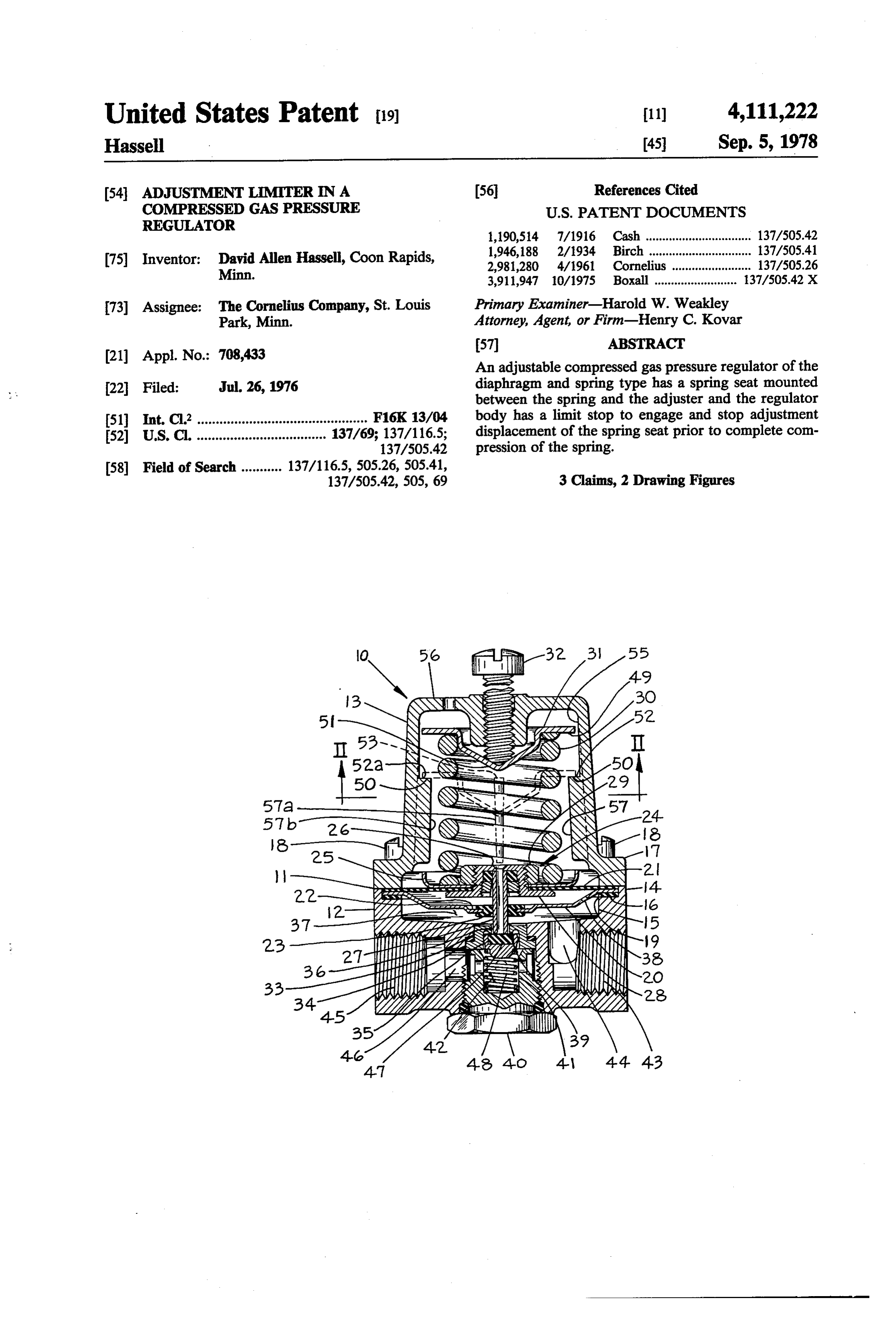
United States Patent (19) 11) 4,111,222 Hassell 45 Sep. 5, 1978 (54) ADJUSTMENT LIMITERNA (56 References Cited COMPRESSED GAS PRESSURE U.S. PATENT DOCUMENTS
REGULATOR
1,190,514 7/1916 Cash ................................ 137/.505.42 1,946,188 2/1934 Birch ............................... 137/.505.41 (75) Inventor: David Allen Hassell, Coon Rapids, 2,981,280 4/1961 Cornelius ........................ 137/.505.26 Minn. 3,911,947 10/1975 Boxall ......................... 137/.505.42 X 73 Assignee: The Cornelius Company, St. Louis Primary Examiner-Harold W. Weakley Park, Minn. Attorney, Agent, or Firm-Henry C. Kovar
(21) Appl. No.: 708,433 An adjustable compressed gas pressure regulator of the 22 Filed: Jul. 26, 1976 diaphragm and spring type has a spring seat mounted between the spring and the adjuster and the regulator 51 Int. Cl’.............................................. F16K 13/04 body has a limit stop to engage and stop adjustment (52) U.S.C. ................................... 137/69; 137/116.5; displacement of the spring seat prior to complete com 137/.505.42 pression of the spring.
58 Field of Search ........... 137/116.5, 505.26, 505.41, 3 Claims, 2 Drawing Figures
SSNS
Page 2
Drawing sheet — no readable text.
Page 3
The most serious result of this practice is that the
ADJUSTMENT LIMITERNA COMPRESSED GAS pressure spring is collapsed to its solid height and the PRESSURE REGULATOR regulator valve is held open and cannot close because the spring no longer functions. Further, the relief func tion of the regulator in U.S. Pat. No. 2,981,280 will no
BACKGROUND OF THE INVENTION longer operate because the valve stem is positively re 1. Field of the Invention s . tained against the valve and the relief port cannot open. This invention pertains to a compressed gas pressure When the pressure regulator valve is held open, the full regulator having an adjustment limiter. pressure of the supply bottle is applied to the beverage 2. Prior Art 10 dispensing system. The typical beverage system has a The prior device is disclosed and fully described in R. working pressure in the range of 25-150 PSIG and the T. Cornelius U.S. Pat. No. 2,981,280 of Apr. 25, 1961. application of approximately 1,000 PSI results in a This regulator has been extremely successful in com bursting of the equipment. This problem is aggravated merce and is widely used by retailers of soft drinks and by regulator users and owners who do not replace dam beer throughout the United States and other countries 15 aged or inoperative pressure gauges and therefore the of the world. The regulator is typically used on metal indicator dials are inaccurate or do not work at all. As bottles of high pressure carbon dioxide which have a an example, if a user has an almost empty gas bottle, he bottle or supply pressure in the range of 700 to 1200 PSI may excessively tighten the adjustment screw and hold - at normal ambient temperatures. The regulator has been open the regulator valve. The proper output pressure made in several models; for example, it has been made 20 would still not be attained because the bottle pressure is available in low pressure, medium pressure and high almost depleted. The regulator user then puts the regu pressure variations. A typical low pressure regulator lator on a new bottle, forgets to back off the regulator will be intended for beer and have an adjustable regulat adjustment and opens the master on-off valve on the gas able output pressure range of 0-60 PSIG; a medium bottle. The full bottle pressure is applied to the dispens pressure regulator for carbonation of cold soft drinks 25 ing system and the system bursts at one of its weakest will have an adjustable regulatable output pressure points. The result at the very best is a horrible mess with range of 0-100 PSIG; and a high pressure regulator for beverage blown over the area immediate to the burst carbonation of a warm soft drink supply will have a ing. More serious is the economic damage and most regulatable output pressure range of 0-160 PSIG. serious would be personal injury. It will be appreciated that beverage retailers hire 30 Another situation is where the gas bottle goes empty many part-time and relatively untrained employees; and the regulator user, in attempting to get the desired many times they will be students or people working output pressure, bottoms out the spring and opens the part-time on weekends or evenings. For the most part regulator valve. The beverage, be it soft drinks or beer, these people are insufficiently trained or not knowl can then backflow through the regulator and into the edgeable in the precautions required in the handling of 35 gas bottle. Obviously, the gas bottle is then contami compressed gases. Many times the retailer and/or his nated and the life expectancy of the bottle may be re employee will completely ignore the instructions given duced due to corrosion from the contaminants. with respect to the usage of compressed gas equipment. OBJECTS OF THE PRESENT INVENTION The problem that has arisen is that the user of the regulator will attempt to adjust the regulator to give an Accordingly, it is an object of the present invention output or regulated pressure in excess of what the de to provide a gas pressure regulator which has a limiting vice was intended for. The easiest way for these people device for controlling the extent of adjustability for to do this has been to go to a toolbox and get a longer pressure.
screw than the adjusting screw supplied with the regu It is an object of the present invention to provide a lator and to install this longer screw and then exces 45 regulator which will give a positive indication of at sively compress the spring to attain a higher output tempted adjustment to an excessively high output pres pressure. The extreme example is substitution of a hex Ste.
head cap screw and usage of a wrench to tighten the cap It is another object of the present invention to pro screw down on the spring. vide a regulator having a pressure limiter of economical It is a normal and accepted commercial practice to 50 configuration.
manufacture and sell regulators with an adjusting screw It is a further object of the present invention to pro precisely of the right length so that it is impossible to vide an improvement in the limitation of over pressur bottom out or compress the spring to solid height. How ization for an existing and known regulator. ever, regulator owners and/or users remove the manu It is yet a further object of this invention to provide a facturer's adjusting screws and substitute their own 55. pressure limiter which can be retrofitted on a known screws. Further, it is an accepted commercial practice regulator.
to provide an external lock nut on a pressure adjusting Many other advantages, features and additional ob screw precisely as is shown in U.S. Pat. No. 2,981,280 jects of the present invention will become manifest to and in fact this construction is presently specified by the those versed in the art upon making reference to the dominant and largest soft drink company in the world detailed description and accompanying drawings in as an equipment standard for its bottlers to comply to. which a preferred structural embodiment incorporating With this construction the owner/user will many times the principles of the present invention is shown by way remove the lock nut, thereby, increasing the effective of illustrative example.
length of the adjusting screw to a length enabling solid compression of the diaphragm spring. It will be appar 65 SUMMARY OF THE INVENTION ent that it is in pure defiance of common sense that In accordance with the principles of this invention, a individuals change the construction of the adjusting compressed gas pressure regulator having a diaphragm screw as they see fit. and spring for biasing the diaphragm to open a pressure
Page 4
control valve is provided with a spring seat positioned upper and lower portions of this pressure chamber 37 between the spring and an adjustment device with the are brought into communication by a gas aperture 38 in spring seat having a margin extending outward beyond the plate 20. The passageway 36 in the bushing 34 also the spring, and the regulator body has a limit stop for communicates with the pressure chamber 37 and is engaging the spring seat and terminating travel and 5 encircled by an annular valve seat 39. The bushing 34 is adjustment of the spring seat prior to complete com held in place within the bore 33 by means of a cap 40 pression of the diaphragm spring. which is screwed into the lower end of the base 12 and
ON THE DRAWINGS
which compressively engages the bushing 34. The cap 40 has a bore 41 lying in continuation of the bore 35.
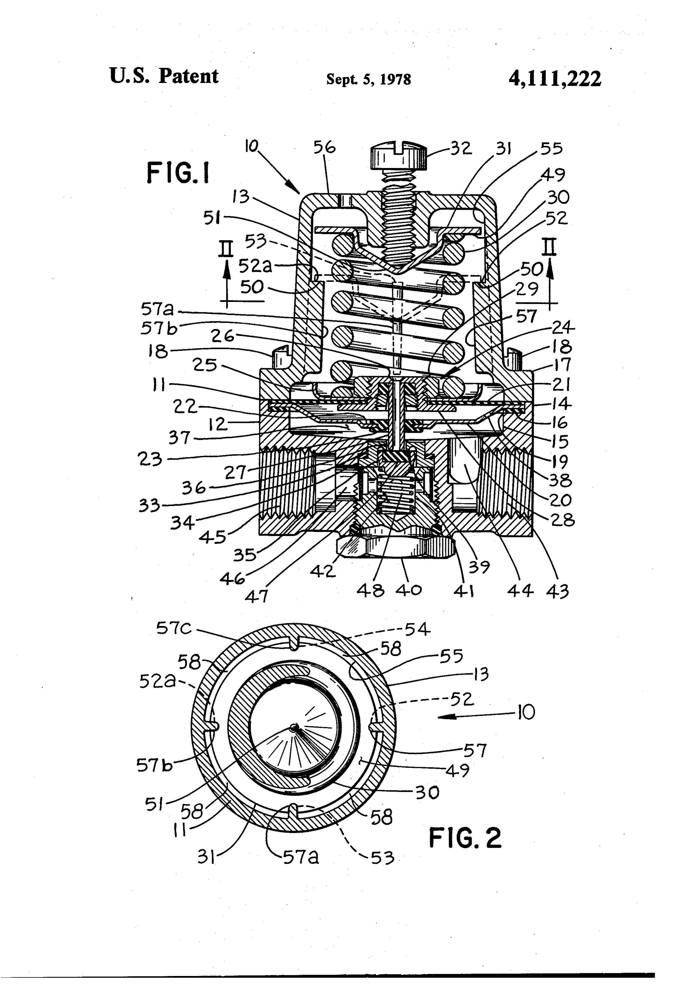
FIG. 1 is a longitudinal elevational sectional view of 10 The bores 35 and 41 form a valve chamber 42. Formed the preferred structural embodiment of an adjustment in the valve base 12 is an outlet 43 which communicates limiter in a compressed gas regulator, provided in ac through a passageway 44 with the pressure chamber 37. cordance with the principles of the present invention; Also found in the valve base 12 is an inlet 45 which and communicates with the valve chamber 42 through a FIG. 2 is an upward looking sectional view taken 15 passageway 46 in the valve body 12. Within the valve through lines II-II in the structure and view of FIG. 1. chamber 42 is mounted a valve head 47 which is opera
AS SHOWN ON THE DRAWINGS
tional to sealingly seat against the valve seat 39 and close the passageway 36 from the valve chamber 42 to
The principles of the present invention are particu the pressure chamber 37. A spring 48 mounted in the larly useful when embodied in a compressed gas pres- 20 cap 40 engages the valve 47 and urges it against the sure regulator of the type illustrated in FIG. 1 and gen valve seat 39.
erally indicated by the numeral 10. Acting between and operatively connecting the The regulator 10 includes a regulator body 11 having mounting 24 and valve 47 is a valve stem or valve actua a valve base 12 and a cover 13. The base 12 is con tor 27. The valve stem 27 extends through the passage structed with an outward extending flange 14 and a 25 way 36 but as the valve stem 27 is a lesser diameter than depression 15 which extends through the flange 14 and the bore forming the passageway 36, the passageway 36 into the base 12. The depression 14 terminates in an is open around the outside of the valve stem 27 for the annular rabbet 16 at the upper portion of the base 12. passage of gas therethrough from valve chamber 42 to Overlying the flange 14 is a cup-shaped cover 13 which regulated pressure chamber 37.
has a flange 17 overlying the base flange 14 and which 30 The operation of the structure so far described is as is secured to the base 12 by means of fastener screws 18 follows: A source of unregulated high pressure gas, for which pass through the cover flange 17 and are screwed example carbon dioxide, at a pressure in the range of into tapped holes in the base flange 14. Extending across 700 to 1200 PSI, or approximately 1000 PSI, is attached the depression 15 and into the rabbet 16 is a gasket 19, to the inlet 45. This gas and the pressure thereof is ap a plate 20 and a diaphragm 21. The diaphragm 21 is 35 plied and present in the valve chamber 42. Initially, if made of rubber or some other similar flexible material the valve 47 is against the valve seat 39, the passageway and the plate 20 is preferably made of metal. The plate 36 is closed. The adjustment means 32 is turned in and 20 is dish-shaped in form and has an offset center por the spring seat 31 is forced into and against the spring tion 22 with an opening 23 extending therethrough. 30, partially compressing the spring 30 and the force These various parts are tightly clamped between the 40 effected thereby is transmitted to the mounting 24 and base flange 14 and the cover flange 17 for holding the to the diaphragm 21. The diaphragm 21 and mounting parts in an operative and assembled relation. 24 move toward the valve 47 under the pressure of the The diaphragm 21 has attached to it a mounting, spring 30 and during this movement the valve stem 27 is generally indicated by the numeral 24, which includes a moved by the mounting 24. The valve stem 27 engages spring plate 25 and means or structure 26 for engaging 45 the valve 47 and forces the valve 47 off the valve seat a valve stem 27. In the embodiment shown, the engager 39. The passageway 36 is then open and high pressure means 26 includes a threaded bushing 28 extending gas flows through the passageway 36 into the pressure through an opening in the diaphragm 21 and the spring chamber 37. When the gas pressure within the pressure plate 25. A nut 29 screwed onto the bushing 28 serves to chamber 37 is sufficient to exert enough force on the clamp the mounting 24 to the diaphragm 21. 50 diaphragm 21 to overcome the force of the spring 30, A spring 30, which is shown as being of a cylindrical the diaphragm 21, mounting 24 and valve stem 27 all helical coil compression type, is mounted within regula move in a direction away from the valve 47 and the tor body 11 and has one end seated against the spring valve 47 reseats against the valve seat 39 and the pas plate 25 and the other end against a spring seat 31 sageway 36 is closed. The pressure within the pressure which, together with the spring 30, is positioned inside 55 chamber 37 is precisely regulatable by adjustment of the of the cover 13. Adjusting means 32, such as the illus adjusting means 32.
trated screw as shown, is provided for positioning the The valve stem 27 is hollow and if the pressure in the spring seat 31 tightly against the spring 30 and for par pressure chamber 37 is excessive, the diaphragm 21, tially compressing the spring 30 for biasing the mount mounting 24 and valve stem 27 will be further forced ing 24 and diaphragm 21 in one direction. The adjusting 60 upward against the spring 30 which will lift the valve means 32 is variably adjustable in position for varying stem 27 off of the valve 47 and the excess gas in pressure the position of the spring seat 31 and therefore the par chamber 37 will pass backwards through the passage tial compression of the spring 30. way 36 and vent through the hollow valve stem 27 and The valve base 12 has a bore 33 in which is mounted out of the cover 13 to atmosphere. a flanged bushing 34 having a bore 35 therein and a 65 An important feature of the present invention is the passageway 36 communicating therewith. The depres provision of structure in the pressure regulator 10 for sion 15 in valve base 12 forms a pressure chamber 37. limiting the amount of compression of the spring 30 so The plate 20 extends through pressure chamber 37 and that the spring 30 is never solidly compressed and so
Page 5
that the mounting 24, and diaphragm 21 are always The spring seat 31 is inside of a cylindrical section 55 movable, both for proper regulation of passage of gas of the regulator cover 13 and the cylindrical section 55 from the valve chamber 42 to the pressure chamber 37 is covered solid by the top 56 and the limit stop 50 is and for relief of any excess pressure within the pressure obstructively in the way for installation and for removal chamber 37." ". . . . . . . . 5. of the spring seat 31,from the cover 13 after the cover
Referring again to FIG. 1, the spring seat 31 will be 13 is removed from the regulator valve base 12. The seen as having an outer margin 49 which extends radi- - regulator cover 13 is a casting, preferably of metal, and ally outward beyond the radial extremities of the spring is cast with a rib 57 or plurality of ribs 57, 57a, 57b, 57c 30. The adjusting means 32 is operable for displacing as shown, and as cast all of the ribs 57, 57a, 57b, 57c the spring seat 31 in a direction toward the mounting 24 10 extend all the way to the cover top 56. That part of the . and in a path and range of travel which will partially rib 57,57a, 57b, 57c in the cylindrical section 55 is re compress the spring 30 to a greater or lesser degree and moved and there remains a portion of each rib 57, 57a, therefore give a relatively high, or low regulated pres 57b, 57c in the cover 13 with the upper surface or end of sure in the pressure chamber 37. There is a limit stop 50 each respective remaining rib portion becoming a re which is mounted in the regulator body 11 and which is 15 spective abutment 52, 53, 54 of limit stop 50. In the in the path of travel of the spring seat 31. The spring i spacings between the ribs 57, 57a, 57b, 57c and abut seat margin 49 is abuttable against the limit stop 50 . iments 52,53, 54 there is provided accesses 58 which when the spring seat 31 is displaced the maximum have a diameter greater than the interior diameter of the amount intended to be possible by the adjusting means . ribs 57, 57a, 57b, 57c or the outer circumference of the 32. When the spring seat margin 49 is abutted against 20, spring seat 13 and which are preferably at least as arcu the limit stop 50 the spring 30 is not completely com ately wide as the arcuate width of a rib 57 and which are pressed to solid height and the mounting means 24 and shown to be much wider. The spring seat 31 can either diaphragm 21 are still movable toward the spring 30 for be installed or removed into or from the cylindrical proper closing operation of the valve 47 against the section 55 by turning the spring seat 31 on edge and valve seat 39 and also for proper operation of the pres 25 sliding the then turned spring seat 31 into the cover 13 sure relief through the hollow valve stem 27. . . . between the ribs 57, 57a, 57b, 57c and through the ac The spring seat 31 has a center section 51 in engage cesses 58 and then turning the spring seat 31 over into its ment with the adjusting means 32. If the adjusting normal mounted operating position as it enters the cy means 32 is driven further toward the mounting 24 with lindrical section 55. . .. excessive force, an example of which would be turning 30 ; : It has been found advantageous to have the regulator a substituted longer screw with a wrench, the center cover 13 fastenably removable from the regulator valve section 51 of the spring seat 31 is rupturable and the -base 12 and to have the cover 13 carry the limit stop 50, adjusting means 32 will rupture through the spring seat adjusting means 32 and spring seat 31 with the margin center section 50 and the regulator 10 will in effect turn . 49 thereon. It will be apparent that this is an extremely off and the regulated pressure will drop to almost zero 35 simple and economical structure and does not require a as the spring seat 31 goes upward about the adjusting costly external knob on the adjusting means. It has been means 32. The spring seat 31 has a center section 51 found that this particular cover 13, adjusting means 32 which is of a lesser thickness of material than the thick and spring seat 31 will fit and operate interchangeably ness of the margin 49 and the spring seat 31 is preferably on the regulator of U.S. Pat. No. 2,981,280 in place of formed of a single piece of material such as soft metal. the original corresponding cover, adjusting means and The relative rigidity of the margin 49 holds the spring spring seat of that regulator as shown and described in seat 31, in position on the limit stop 50 and does not that patent. In use of this regulator, a retail beverage allow further compression of the spring 30 even while dealer will usually lease or rent the regulator from a the spring seat center section 51 is under a force from bottling or brewery plant. While most bottling and the adjusting means 32 which is close to or sufficient to 45 brewery personnel are knowledgeable in pressure regu rupture the centersection 51. The limitstop 50 is placed lators, most retailers and hired employees of retailers immediately adjacent to and outside of the spring 30 are not. If the retailer or his employee forces the regula which gives a minimal conical deflection of the spring tor beyond its intended pressure adjustment, the rup seat 31 in the event the adjusting means 32 is turned in tured spring seat 31 will need replacement and the bot or adjusted in excess of what is intended to be the nor 50 tler, brewer and retailer will then know, or at least have mal range and this also helps in assuring that the spring indications, that corrective and remedial training of 30 is not overly compressed. some worker may be needed to prevent repetition of The limit stop 50 may be formed of at least two indi such rupturement for avoidance of any type of accident vidual abutments 52, 52a which are spaced from each with the compressed gas equipment and avoidance of other and would be on opposite sides of the spring 30 as 55 any possible damage to the beverage equipment or the shown. It has been found preferable to have a third retail location per se.
abutment 53 because it is then impossible for a properly Although various and minor modifications may be sized spring seat 31 to tip off of the limit stop 50. In the suggested by those versed in the art, it should be under embodiment shown, as best seen in FIG. 2, there are stood that I wish to embody within the scope of the provided four abutments 52, 52a, 53, and 54. The spring 60 patent warranted hereon, all such embodiments as rea seat margin 49 extends uninterrupted around the en sonably and properly come within the scope of my tirety of the circumference of the spring seat 31 which contribution to the art.
gives maximum strength to the margin 49 and also as I claim as my invention:
sures that the margin 49 will engage all of the abutments 1. In a compressed gas pressure regulator having a 52, 52a, 53 and 54, which lie in a plane parallel to the 65 regulator body, a diaphragm of flexible material carried diaphragm 21 so that when the spring seat 31 is abutted thereby, a mounting carried by the diaphragm, a spring down against the limit stop 50, it is parallel to the dia operatively positioned between the regulator body and phragm 21 and the spring 30 is not cocked or twisted. the mounting, means mounted in the body and adjust
Page 6
ably operative upon the spring for partially compress and the diaphragm in one direction, a pressure chamber ing the spring into operative engagement against the in the body and adjacent to the diaphragm, a valve mounting for movably biasing the mounting and the chamber in the body, an inlet to the valve chamber and diaphragm in one direction, a pressure chamber in the an outlet from the pressure chamber, a passageway body and adjacent to the diaphragm, a valve chamber in 5 connecting the pressure and valve chambers, a valve the body, an inlet to the valve chamber and an outlet seat in the valve chamber spaced from the mounting from the pressure chamber, a passageway connecting plate and surrounding the passageway, a valve head in the pressure and valve chambers, a valve seat in the the valve chamber and adapted to sealingly seat against valve chamber spaced from the mounting and surround the valve seat and close the passageway, and means ing the passageway, a valve head in the valve chamber 10 operative between the mounting plate and valve head and adapted to sealingly seat against the valve seat and for unseating the valve head upon movement of the close the passageway, and means between the mounting mounting plate and diaphragm in the direction as biased and the valve head for unseating the valve head upon by the spring for opening the passageway, a spring seat movement of the mounting and diaphragm in the direc mounted within the cover just under the cover top and tion as biased by the spring for opening the passageway, 15 between the spring and the adjustment means with said the improvement, comprising in combination therewith: spring seat being displaceable by said adjustment means a. a spring seat mounted between the spring and the through a path and range of travel sufficient for par adjustment means, the spring seat being displace tially compressing the spring against the mounting able by the adjustment means through a path and plate, an outer margin on the spring seat, with said range of travel for partially compressing the spring 20 margin extending radially outward beyond and com against the mounting; pletely around the entire circumference of the spring, b. an outer margin on the spring seat, the margin and a limit stop in the body cover and in the path of extending radially outward beyond the spring; displaceable travel of the spring seat with the spring c. a limit stop mounted in the body and in the path of seat margin and the limit stop being abuttable against displaceable travel of the spring seat, the margin 25. each other prior to complete compression of the spring and limit stop being abuttable against each other for terminating possible displacement of the spring seat prior to complete compression of the spring for and limiting compression of the spring, the improve terminating displacement of the spring seat and ment, comprising in combination therewith: limiting compression of the spring; and at least three individual internal straight elongate ribs d. a rupturable centersection in the spring seat and in 30 cast integrally with and as part of the cover, said engagement with the adjusting means, the center ribs being spaced radially from one another around section being rupturable upon operation of the the inside of the cover and around the outside of adjustment means in a direction toward the mount the spring and being positioned co-axially with the ing when the margin and limit stop are abutted spring, said ribs as cast all being adjoined directly against each other. 35 to the cover top and extending uninterruptedly 2. A regulator according to claim 1, in which the from the cover top past the spring seat and spring spring seat is formed of a single piece of material, and and nearly to the spring mounting plate, the center section is of a lesser thickness than the thick each rib having that part of its as-cast self originally ness of the margin. between the limit stop and the cover top removed 3. In a compressed gas pressure regulator having a 40 from the casting such that there is only a portion of regulator body including a cover formed of a casting, a each of the as-cast rib remaining with an end base fastenably attached to and removable from the formed on each remaining rib portion facing cover, a diaphragm of flexible material carried by said toward the cover top and the spring seat margin, base and said cover, a spring mounting plate carried by all of such rib ends jointly forming said limit stop, the diaphragm, a spring operatively positioned between 45 and the regulator body and the mounting plate, a top on the an access in a radial spacing between the ribs with the body cover, means mounted in the cover top and adjust spring seat being installable into and removable ably operative against the spring for partially compress from its operative position within the cover by ing the spring into operative engagement against the passage through thea access. mounting plate for movably biasing the mounting plate 50
Provenance
- Collection
- Cited prior art
- Original PDF
- patentimages.storage.googleapis.com →
- Filed
- 1976-07-26
- Pages
- 6
- Method
- pdftotext (the PDF's own text layer) + pdftoppm 300dpi page scans
- Source
- Google Patents bibliographic record
- Granted
- 1978-09-05
- Inventors
- David Allen Hassell; Cornelius Co
- Transcribed from
- patentimages.storage.googleapis.com →