patent · US3378206
Adjustable flow controller
16 April 1968
Page 1
Drawing sheet — no readable text.
Page 2
United States Patent Office 3,378,206 Patented Apr. 16, 1968
for directing flow of fluid through a passage without chang 3,378,206 ing the open area thereof as the flow direction is changed. ADUSTABLE FLOW CONTROLLER Still a further object of the invention is to provide Lee G. Poe, Toledo, and Norman T. Ferguson, Maumee means for supplying air or fuel to a burner from different Ohio, assignors to Midland-Ross Corporation, Toledo, directions
Ohio, a corporation of Ohio without affecting the air-fuel ratio. Filed Mar. 21, 1966, Ser. No. 535,887 Other objects and advantages of the invention will 6 Claims. (Cl. 239-402.5) be apparent from the following detailed description of a preferred embodiment thereof, reference being made to the accompanying drawing, in which:
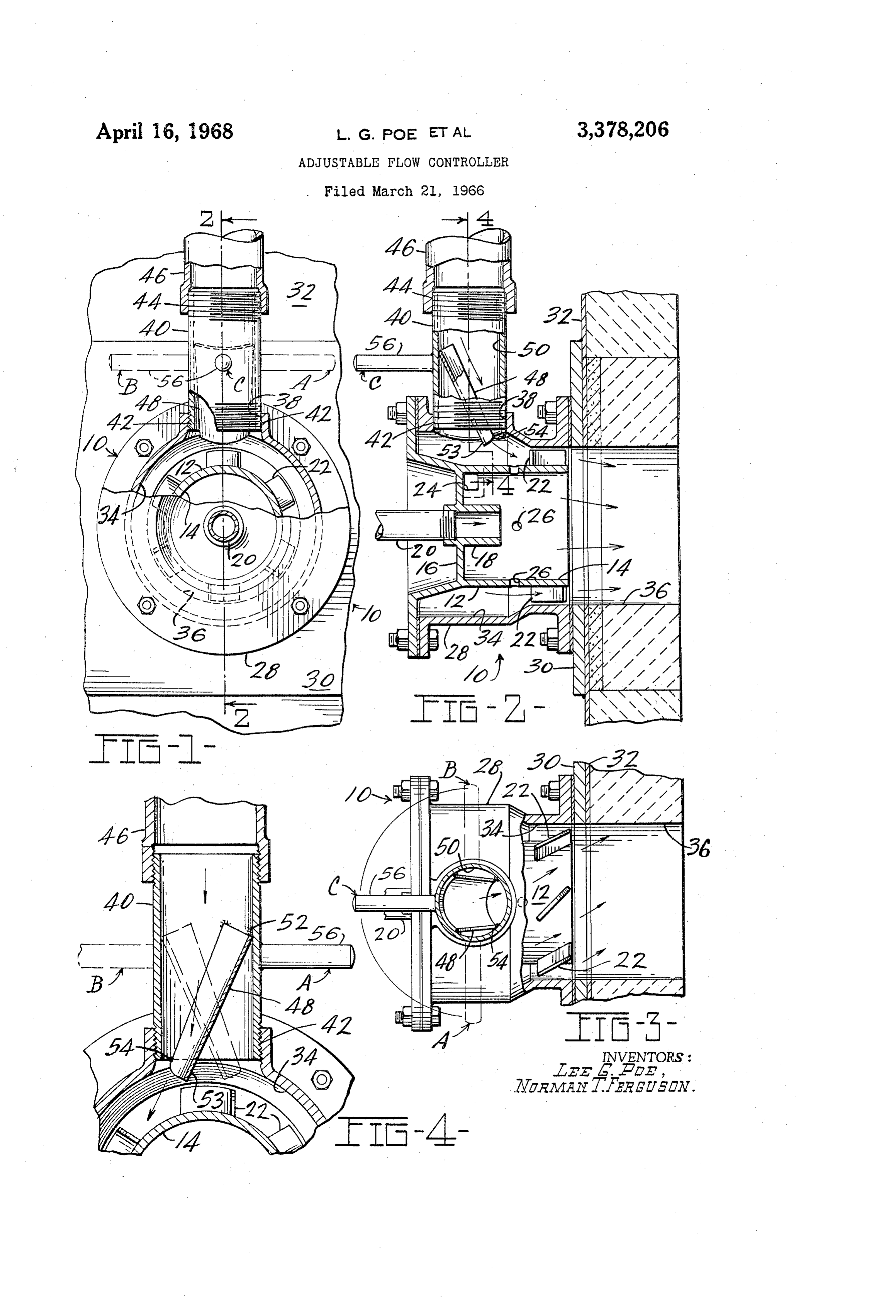
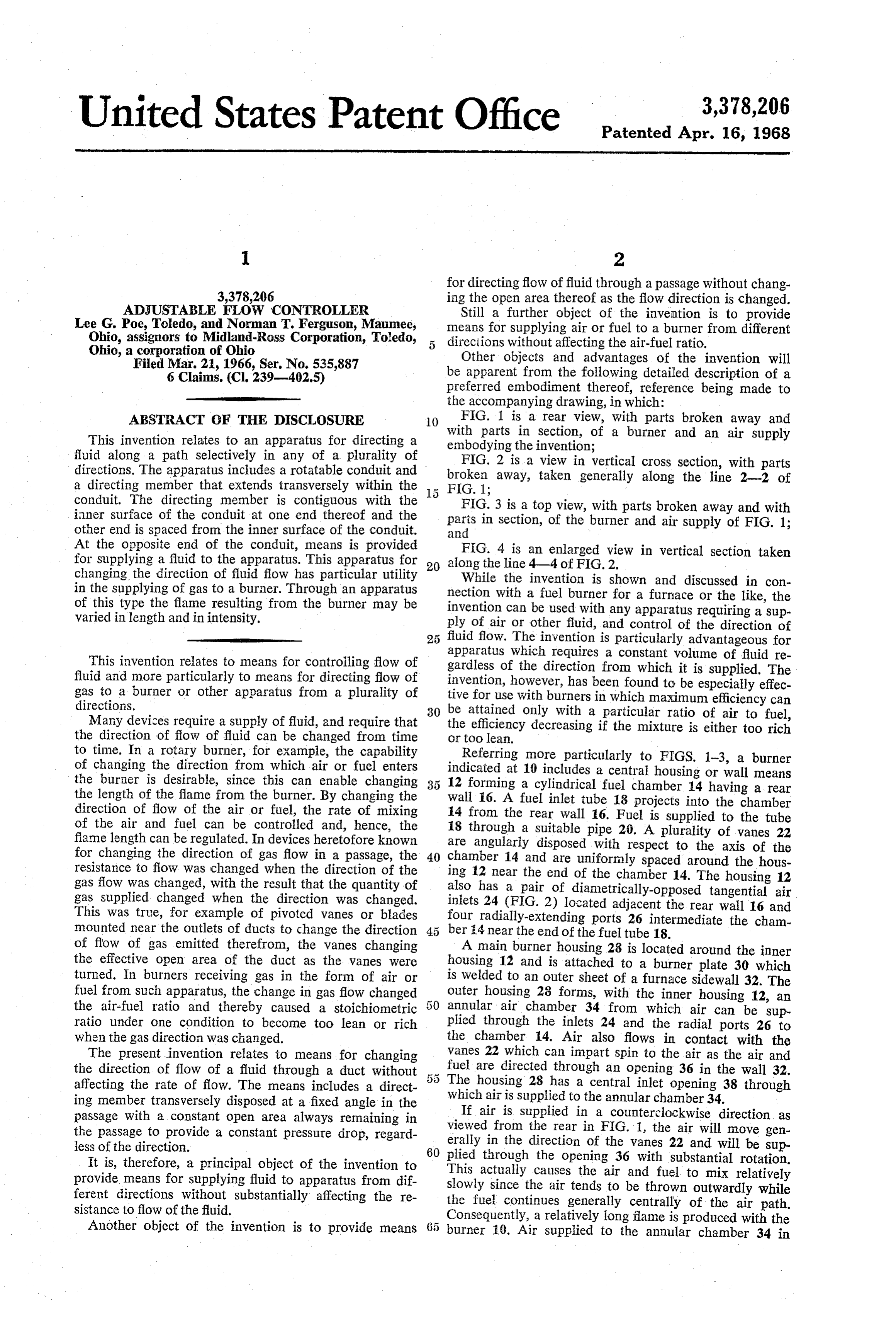
ABSTRACT OF THE DISCLOSURE () FIG. 1 is a rear view, with parts broken away and This invention relates to an apparatus for directing a with parts in section, of a burner and an air supply fluid along a path selectively in any of a plurality of embodying the invention;
directions. The apparatus includes a rotatable conduit and broken away,a taken
FIG. 2 is view in vertical cross section, with parts generally along the line 2-2 of a directing member that extends transversely within the conduit. The directing member is contiguous with the FIG. 1;
FIG. 3 is a top view, with parts broken away and with inner surface of the conduit at one end thereof and the parts other end is spaced from the inner surface of the conduit. and in section, of the burner and air supply of FIG. 1; At the opposite end of the conduit, means is provided FIG. 4 is an enlarged view in vertical section taken for supplying a fluid to the apparatus. This apparatus for 20 along the line 4-4 of FIG. 2.
changing the direction of fluid flow has particular utility While the invention is shown and discussed in con in the supplying of gas to a burner. Through an apparatus nection with a fuel burner for a furnace or the like, the of this type the flame resulting from the burner may be invention can be used with any apparatus requiring a sup varied in length and in intensity. ply of air or other fluid, and control of the direction of fluid flow. The invention is particularly advantageous for apparatus which requires a constant volume of fluid re
This invention relates to means for controlling flow of gardless fluid and more particularly to means for directing flow of invention,ofhowever, the direction from which it is supplied. The has been found to be especially effec gas to a burner or other apparatus from a plurality of tive for use with burners in which maximum efficiency can directions. 30 be attained only with a particular ratio of air to fuel, Many devices require a supply of fluid, and require that the direction of flow of fluid can be changed from time the efficiency decreasing if the mixture is either too rich or too lean.
to time. In a rotary burner, for example, the capability Referring more particularly to FIGS. 1-3, a burner of changing the direction from which air or fuel enters indicated the burner is desirable, since this can enable changing 12 formingat a10cylindrical includes a central housing or wall means the length of the flame from the burner. By changing the wall i6. A fuel inlet tubefuel 18 chamber 14 having a rear projects into the chamber direction of flow of the air or fuel, the rate of mixing 14 from the rear wall 16. Fuel is supplied to the tube of the air and fuel can be controlled and, hence, the flame length can be regulated. In devices heretofore known are angularly disposed with respectplurality 18 through a suitable pipe 20. A of vanes 22 for changing the direction of gas flow in a passage, the 40 chamber 14 and are uniformly spaced aroundaxistheofhous
resistance to flow was changed when the direction of the ing 12 near the end of the chamber 14. The housing 12 gas flow was changed, with the result that the quantity of gas supplied changed when the direction was changed. also has a pair of diametrically-opposed tangential air This was true, for example of pivoted vanes or blades inlets four 24 (FIG. 2) located adjacent the rear wall 16 and radially-extending ports 26 intermediate the cham mounted near the outlets of ducts to change the direction ber 4 near the end of the fuel tube 18. of flow of gas emitted therefronn, the vanes changing A main burner housing 28 is located around the inner the effective open area of the duct as the vanes were housing 12 and is attached to a burner plate 30 which turned. In burners receiving gas in the form of air or is Welded to an outer sheet of a furnace sidewall 32. The fuel from such apparatus, the change in gas flow changed outer housing 28 forms, with the inner housing 12, an the air-fuel ratio and thereby caused a stoichiometric annular air chamber 34 from which air can be sup ratio under one condition to become too lean or rich plied through the inlets 24 and the radial ports 26 to when the gas direction was changed. the chamber 14. Air also flows in contact with the The present invention relates to means for changing vanes 22 which can impart spin to the air as the air and the direction of flow of a fluid through a duct without 55 fuel are directed through an opening 36 in the wall 32. affecting the rate of flow. The means includes a direct The housing 28 has a central inlet opening 38 through ing member transversely disposed at a fixed angle in the which air is supplied to the annular chamber 34. passage with a constant open area always remaining in If air is supplied in a counterclockwise direction as the passage to provide a constant pressure drop, regard viewed from the rear in FIG. 1, the air will move gen less of the direction. erally in the direction of the vanes 22 and will be sup 60 plied through the opening 36 with substantial rotation.
It is, therefore, a principal object of the invention to This provide means for supplying fluid to apparatus from dif slowlyactually causes the air and fuel to mix relatively since the air tends to be thrown outwardly while ferent directions without substantially affecting the re the fuel continues generally centrally of the air path. sistance to fiow of the fluid. Consequently, a relatively long flame is produced with the Another object of the invention is to provide means burner 10. Air supplied to the annular chamber 34 in
Page 3
a clockwise direction tends to move perpendicularly to vention, if they are within the spirit and the tenor of the the vanes 22 with the result that a substantial amount of accompanying claims.
turbulence is caused and rapid mixing of the air and We claim:
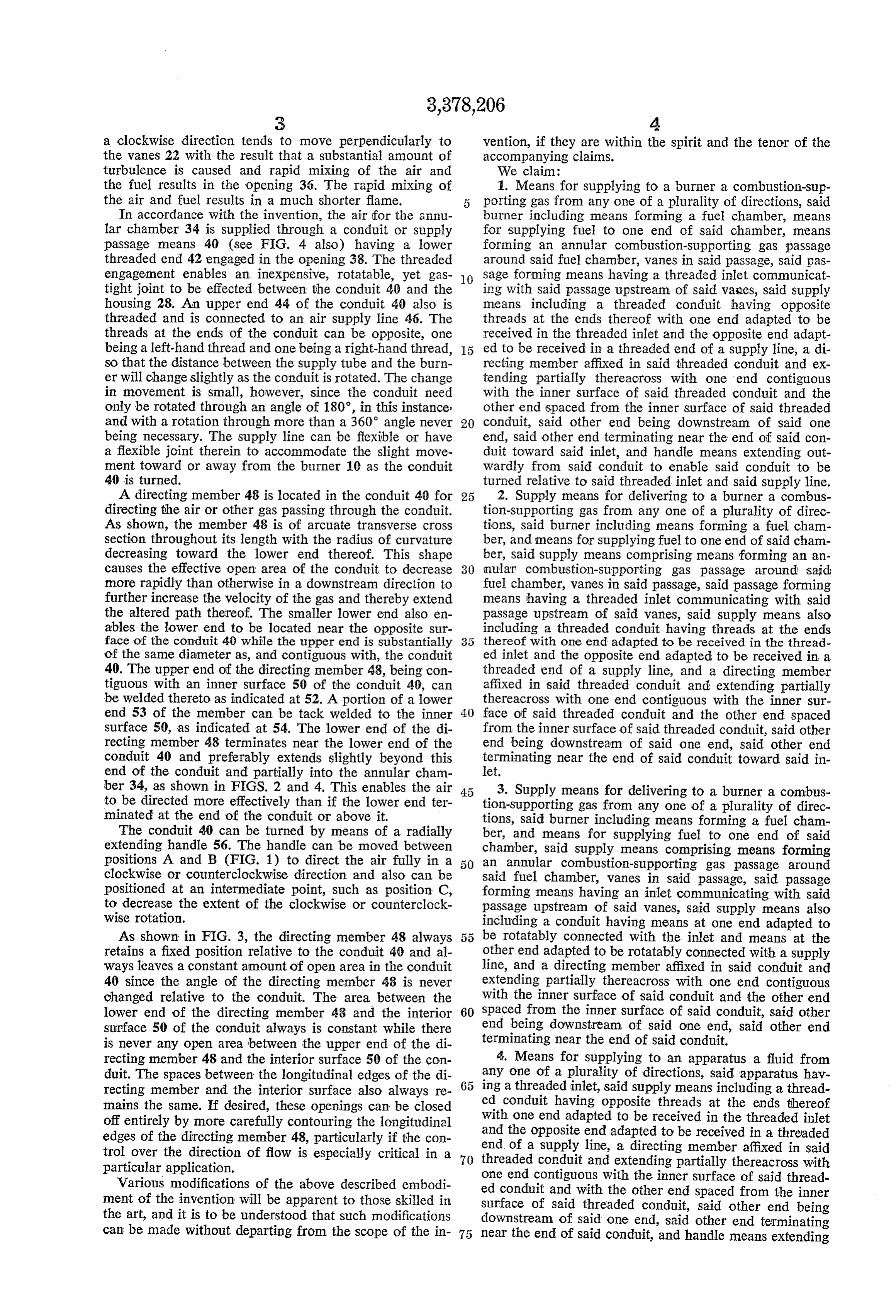
the fuel results in the opening 36. The rapid mixing of 1. Means for supplying to a burner a combustion-sup the air and fuel results in a much shorter flame. porting gas from any one of a plurality of directions, said In accordance with the invention, the air for the annu burner including means forming a fuel chamber, means lar chamber 34 is supplied through a conduit or supply for supplying fuel to one end of said chamber, means passage means 40 (see FIG. 4 also) having a lower forming an annular combustion-supporting gas passage threaded end 42 engaged in the opening 38. The threaded around Said fuel chamber, vanes in said passage, said pas engagement enables an inexpensive, rotatable, yet gas O Sage forming means having a threaded inlet communicat tight joint to be effected between the conduit 40 and the ing with said passage upstream of said values, said supply housing 28. An upper end 44 of the conduit 40 also is means including a threaded conduit having opposite threaded and is connected to an air supply line 46. The threads at the ends thereof with one end adapted to be threads at the ends of the conduit can be opposite, one received in the threaded inlet and the opposite end adapt being a left-hand thread and one being a right-hand thread, ed to be received in a threaded end of a supply line, a di so that the distance between the supply tube and the burn recting member affixed in said threaded conduit and ex er will change slightly as the conduit is rotated. The change tending partially thereacross with one end contiguous in movement is small, however, since the conduit need with the inner surface of said threaded conduit and the only be rotated through an angle of 180°, in this instance other end spaced from the inner surface of said threaded and with a rotation through more than a 360° angle never 20 conduit, said other end being downstream of said one being necessary. The supply line can be flexible or have end, said other end terminating near the end of said con a flexible joint therein to accommodate the slight move duit toward said inlet, and handle means extending out ment toward or away from the burner 10 as the conduit wardly from said conduit to enable said conduit to be 40 is turned. turned relative to said threaded inlet and said supply line. A directing member 48 is located in the conduit 40 for 2. Supply means for delivering to a burner a combus directing the air or other gas passing through the conduit. tion-supporting gas from any one of a plurality of direc As shown, the member 48 is of arcuate transverse cross tions, said burner including means forming a fuel cham section throughout its length with the radius of curvature ber, and means for supplying fuel to one end of said cham decreasing toward the lower end thereof. This shape ber, said supply means comprising means forming an an causes the effective open area of the conduit to decrease 30 nular combustion-supporting gas passage around said: more rapidly than otherwise in a downstream direction to fuel chamber, vanes in said passage, said passage forming further increase the velocity of the gas and thereby extend means having a threaded inlet communicating with said the altered path thereof. The smaller lower end also en passage upstream of said vanes, said supply means also ables the lower end to be located near the opposite sur including a threaded conduit having threads at the ends face of the conduit 40 while the upper end is substantially thereof with one end adapted to be received in the thread of the same diameter as, and contiguous with, the conduit ed inlet and the opposite end adapted to be received in a 40. The upper end of the directing member 48, being con threaded end of a supply line, and a directing member tiguous with an inner surface 50 of the conduit 40, can affixed in said threaded conduit and extending partially be welded thereto as indicated at 52. A portion of a lower thereacross with one end contiguous with the inner sur end 53 of the member can be tack welded to the inner 40 face of said threaded conduit and the other end spaced surface 50, as indicated at 54. The lower end of the di from the inner surface of said threaded conduit, said other recting member 48 terminates near the lower end of the end being downstream of said one end, said other end conduit 40 and preferably extends slightly beyond this terminating near the end of said conduit toward said in end of the conduit and partially into the annular cham let.
ber 34, as shown in FIGS. 2 and 4. This enables the air 3. Supply means for delivering to a burner a combus to be directed more effectively than if the lower end ter tion-Supporting gas from any one of a plurality of direc minated at the end of the conduit or above it. tions, said burner including means forming a fuel cham The conduit 40 can be turned by means of a radially ber, and means for supplying fuel to one end of said extending handle 56. The handle can be moved between chamber, said supply means comprising means forming positions A and B (FIG. 1) to direct the air fully in a an annular combustion-supporting gas passage around clockwise or counterclockwise direction and also can be said fuel chamber, vanes in said passage, said passage positioned at an intermediate point, such as position C, forming means having an inlet communicating with said to decrease the extent of the clockwise or counterclock passage upstream of said vanes, said supply means also wise rotation. including a conduit having means at one end adapted to As shown in FIG. 3, the directing member 48 always 5 5 be rotatably connected with the inlet and means at the retains a fixed position relative to the conduit 40 and al other end adapted to be rotatably connected with a supply ways leaves a constant amount of open area in the conduit line, and a directing member affixed in said conduit and 40 since the angle of the directing member 48 is never extending partially thereacross with one end contiguous changed relative to the conduit. The area between the with the inner surface of said conduit and the other end lower end of the directing member 48 and the interior 60 Spaced from the inner surface of said conduit, said other surface 50 of the conduit always is constant while there end being downstream of said one end, said other end is never any open area between the upper end of the di terminating near the end of said conduit. recting member 48 and the interior surface 50 of the con 4. Means for Supplying to an apparatus a fluid from duit. The spaces between the longitudinal edges of the di 65 any one of a plurality of directions, said apparatus hav recting member and the interior surface also always re ing a threaded inlet, said supply means including a thread mains the same. If desired, these openings can be closed ed conduit having opposite threads at the ends thereof off entirely by more carefully contouring the longitudinal with one end adapted to be received in the threaded inlet edges of the directing member 48, particularly if the con end and the opposite end adapted to be received in a threaded of a supply line, a directing member affixed in said trol over the direction of flow is especially critical in a 70 threaded particular application. conduit and extending partially thereacross with Various modifications of the above described embodi One end contiguous with the inner surface of said thread ment of the invention will be apparent to those skilled in ed conduit and with the other end spaced from the inner the art, and it is to be understood that such modifications Surface of said threaded conduit, said other end being can be made without departing from the scope of the in 75 downstream of said one end, said other end terminating near the end of Said conduit, and handle means extending
Page 4
outwardly from said conduit to enable said conduit to be spaced from the inner surface of said conduit, said other turned relative to said threaded inlet and said supply end being downstream of said one end, said other end line. terminating near the end of said conduit. 5. Means for supplying to an apparatus a fluid from any one of a plurality of directions, said apparatus hav References Cited ing a threaded inlet, said supply means including a thread UNITED STATES PATENTS ed conduit having threads at the ends thereof with one end adapted to be received in the threaded inlet and the 362,917 5/1887 Exner -------------- 137-610 opposite end adapted to be received in a threaded end 422,770 3/1890 Grassner ----------- 137-610 of a supply line, and a directing member affixed in said 0. 850,762 4/1907 Kolla —————————————— 137-610 threaded conduit and extending partially thereacross with 1 ? ,333142 3/1920 Uimer ----------?--------- 138-37 one end contiguous with the inner surface of said threaded 1,494,351 5/1924 Gillard ------------ 138-37 X conduit and with the other end spaced from the inner 1,593,186 7/1926 McKean et al. ----- 239- 405 X surface of said threaded conduit, said other end being 1,790,927 2/1931 Kreager ----------- 239-402.5 downstream of said one end, said other end terminating 3,153,438 10/1964 Brzozowski ------- 239-405 X near the end of said conduit. 3,195,609 7/1965 Nesbitt et al. ---------- 158-7 6. Means for supplying to an apparatus a fluid from 3,199,537 8/1965 Swanson ---------- 137-610 X any one of a plurality of directions, said apparatus having FOREIGN PATENTS a threaded inlet, said supply means including a conduit having means at one end adapted to be rotatably con 20 30,445 11/1959 Finland. nected with the inlet and means at the opposite end adapt 339,466 4/1936 Italy. ed to be rotatably connected with an end of a supply line, and a directing member affixed in said conduit and extend M. HENSON WOOD, JR., Primary Examiner. ing partially thereacross with one end contiguous with VAN C. WILKS, Assistant Examiner. the inner surface of said conduit and with the other end
Provenance
- Collection
- Cited prior art
- Original PDF
- patentimages.storage.googleapis.com →
- Filed
- 1966-03-21
- Pages
- 4
- Method
- pdftotext (the PDF's own text layer) + pdftoppm 300dpi page scans
- Source
- Google Patents bibliographic record
- Granted
- 1968-04-16
- Inventors
- Lee G Poe; Norman T Ferguson; Midland Ross Corp
- Transcribed from
- patentimages.storage.googleapis.com →