patent · US1142761
Apparatus for dehydrating petroleum-oil.
8 June 1915
Page 1
Drawing sheet — no readable text.
Page 2
UNITED STATES PATENT OFFICE.
ROBERT E. LARD AND JOSEPH. H. RANEY, OF TAFT, CALIFORNIA, ASSGNORS TO
RANEY-LAIRD PETROLEUM DEHYDRATING COMPANY, OF Los ANGELES, CALL
FORNIA, A CORPORATION OF CALIFORNIA.
APPARATUS FOR DEHYDRATING PETROLEUM-ori.
1,142,761. Specification of Letters Patent. Patented June 8, 1915. Application filed October 26, 1914. Serial No. 868,774.
To all whom it may concern: of oil between the water particles to coalesce Be it known that we, RoBERT E. LAIRD them into free globules. 55 We have further found that by connecting and JosepH. H. RAN EY, citizens of the United a condenser across the terminals of the treat States, both residing at Taft, in the county of Kern and State of California, have in ers that a further power economy is possible, and a further object of our invention is to vented a new and useful Apparatus for De provide such a condenser. 60 hydrating Petroleum-Oil, of which the fol Referring to the drawings, which are for lowing is a specification.
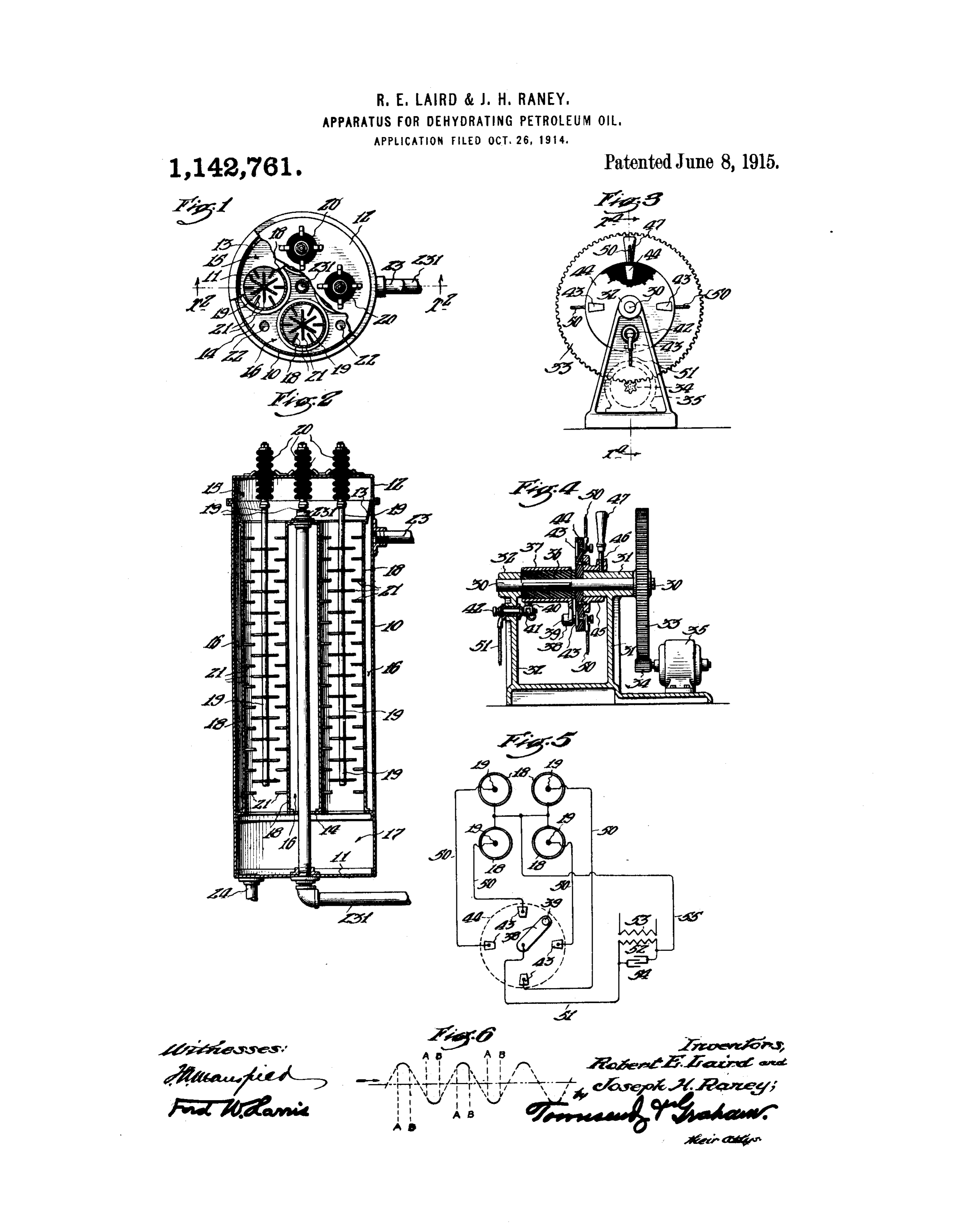
The invention relates to the art of dehy illustrative purposes only, Figure 1 is a plan 0 drating crude petroleum, and the principal view of the treater, a portion thereof being object of the invention is to provide a proc broken away and shown in section to better 65 ess and apparatus which will remove the shows illustrate the internal structure. Fig. 2 water from petroleum emulsions. a Section on the plane a-a” of Fig. 1. Crude petroleum in its natural state is Fig. 3 is an end elevation of a distributer. 15 often found mixed with water. This water Fig. 4 is a partial Section on the plane ae'-a' appears in two forms: first, as free water of Fig. 3. Fig. 5 is a diagram of connec tions of the apparatus, and Fig. 6 is a 70 which will readily settle out if the mixture graphical representation of the alternating is allowed to stand, and, second, as trapped or emulsified water which will not settle out voltage wave.
20 even if the mixture is allowed to stand for In Our invention we employ a treater long periods. The emulsion consists of very which consists of an outer shell 10 having a tight bottom 11 and a removalble top 12. 75 minute particles of water embedded in the Secured mass of oil, and the principal object of our dividing inwallthe14,shell 10 is a pan 13 and a invention is to break up the films between ing the interior of the pan and wall divid the treater into an upper 25 the various water particles so that they will coalesce into larger globules of free water. chamber 15, a central chamber 16 and a 80 We have found that this can be done by lower chainher 17. Secured in the pan 13 causing very heavy currents to flow momen and the wall 14 are a plurality of cylindrical tarily through the body of emulsion and in outer electrodes 18, these electrodes having a 30 terrupting these currents at regular inter tight closure with the pan 13 and the wall vals to allow the free water to settle out of 14 and providing an open passage there the mass of oil. We have further found that through between the chambers 15 and 17. An inner electrode 19 is suspended in the cen an alternating current is well suited to this ter work, and we provide a distributer whereby of each of the outer electrodes 18, being 35 an alternating electromotive force may be Secured in an insulator 20 carried by the top intermittently impressed upon suitable elec 12 of the treater. Extending outwardly trodes immersed in the emulsion. We have from the electrodes 19 and inwardly from 90 also found that by driving this distributer in the electrodes 18 are a series of points 21 synchronism with the source of alternating between which the electrical discharge takes 40 electromotive force, and by so adjusting the place through the emulsion. A series of distributer that only the extreme peaks df openings viding 22 are provided in the wall 14 pro 95 open passages between the cham the alternating wave are utilized, that large power economies are possible over previous bers 16 and 17. An emulsion inlet pipe 23 methods, such as those disclosed by usin our opens into the top of the chamber 16 and an 45 application for patent Serial No. 852,483, oil outlet pipe 231 extends upwardly through the bottom 11, through the wall 14, and 00 for apparatus for treating emulsions, filed through by us on July 22, 1914, and now pending the pan 13 into the upper chamber before the United States Patent Office. 15. A water outlet pipe 24 is tightly sc A further object of our invention is to cured in the botton 11, opening into the 50 connect the distributer to a synchronous mo chamber 17. Emulsion is admitted through tor and to provide adjusting means on the the chamberpipe 23, flowing downwardly through distributer so that the peaks of the voltage the
16 around the outer electrodes 05 through the openings 22 into the wave are utilized in breaking down the films
Page 3
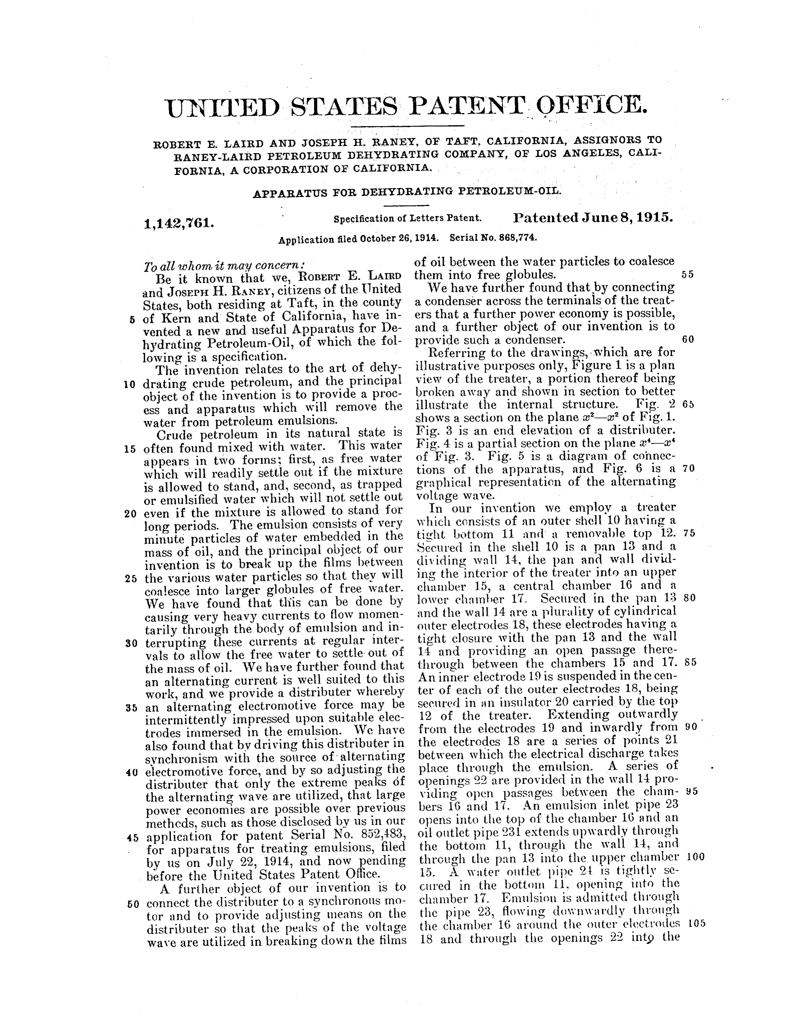
chamber 17, thereafter passing upwardly at a certain frequency through a suitable through the outer electrodes 18 into the Source on the primary 53 of the transformer. chanaber 15 between the points 21. In its This in turn induces a situilar electromotive passage through the outer electrodes 18, the force of the same frequency on the second 5 emulsion is separated into free oil and free ary 52 of the transformer, and this electro 70 water, the free oil rising and passing out motive force is impressed through the wires wardly through the pipe 231 and the water 51 and 55 on the outer electrodes 18 and on falling and being drawn off through the the moving contact brush 39. Since the pine 24. moving contact brush 39 is connected O The particular form of treater above de through the shaft 30 and the gear 33 and 75 scribed is adopted for illustrative purposes the pinion 34 with the synchronous motor only and forms no part of the present inven 35, the brush 39 will move in exact syn tion, being fully illustrated and described chronism in our application for patent Serial No. and it willwith the source of electric power make contact with each of the 5 852,482, filed by us on July 22, 1914. segments 43 at a certain definite place in For the purpose of regulating and con the voltage wave which is graphically trolling the electromotive force impressed on shown in Fig. 6, in which horizontal dis the electrodes 18 and 19, the distributer tances represent time and vertical distances illustrated in Figs. 3 and 4 may be used. represent magnitude of electromotive force. 20 This distributer consists of a shaft 30 car The sleeve 45 is suitably adjusted by means 85 ried in suitable bearings 31 and 32 and of the handle 47 and the stud 46 so that the driven by means of a gear 33 from a pin moving contact brush 39 makes contact with ion 34 on a synchronous motor 35. This one of the segments 43 at an instant marked synchronous motor may be of any of the A in Fig. 6, and that it breaks contact at 25 well known forms, the only requirement the instant marked B in Fig. 6. The result 90 being that its speed of rotation be an exact is that only those portions of the electro divisor of the frequencv of the source of motive force wave shown in full lines in electricity. Rigidly secured to the shaft30 is Fig. 6 are innpressed upon the electrodes 18 an insulating sleeve 36 upon which is mounted 30 a collector ring 37 which carries an arm 38 and 19, a current flowing between the elec 95 trodes 18 and 19 during the interval repre having a moving contact brush 39 elastically sented by the instances marked A, B, secured therein. A stationary contact brush graphically shown in Fig. 6. The result is 40 carried in a brush holder 41 on a stud 42 that only the extreme peak of maximum makes contact with the ring 37 and is suit value of the voltage wave acts upon the 35 ably insulated from and secured to the bear emulsion, and as soon as this wave starts to OO ing 32. The moving contact brush 39 is so decrease connection is broken and the cur placed as to successively contact with a se rent ceases, thus allowing the trapped wa ries of stationary contacts 43 which are rig ter which has been broken up by the cur idly secured in an insulating plate 44 car rent to separate into large globules and 40 ried on a sleeve 45 mounted on the bearing drop out of the electric field between the 31. Threaded in the sleeve 45 is a stud 46 electrodes 18 and 19.
having an insulating handle 47 formed The Swnchronous motor may be of any thereon, the purpose of the stud 46 and the desired form. A common one is that hav handle 47 being to secure the sleeve 45 in ing a direct current field winding and an 45 various angular positions about the bearing alternating current armature. Such motors 10 31, the stud 46 being rotated by the handle run in exact synchronism with the supply to press against the bearing 31 and lock the circuit as contrasted with the ordinary in sleeve 45 in any angular position. duction motors which run slightly slower,
The method of connection is illustrated in the difference in speed in induction motors Fig. 5 in which four outer electrodes 18 are being known as the slip. The distributer 5 shown, each having its inner electrode 19 con shown is largely diagrammatic, there being nected through a suitable wire 50 with one generally more contacts 43 as a complete of the segments 43 of the distributer. The treating plant will generally consist of at moving arm 38 and the brush 39 are con least 16 inner electrodes. In some cases 55 nected through a wire 51 with a secondary where a high frequency is used the distribul 52 of a transformer having a primary 53 ter is directly connected to the armature connected to the alternating source of elec shaft of the synchronous motor. In the tricity. Connected across the secondary 52 case of a 25 cycle distributer having four is a condenser 54, the secondary 52 and the 60 condenser 54 being connected through a wire contacts 43 we nrefer to run the motor 35
55 with all of the outer electrodes 18. R. P. M. or 12, R. P. S. with four contacts The method of operation of the invention 43, this gives us 50 makes and breaks per is as follows: The emulsion being circulated second or one per alternation. With 16 through the treater, as previously described, 65 alternating electromotive force is impressed treaters the gear ratio would be 8 to 1, the
Page 4
relative portio of each alternation of the
R. P. S. This multiplied by 16 contacts electromotive gives us 50 makes and breaks per second or force is impressed on the elec one per alternation. It is not however nec trodes.
2. Apparatus for treating petroleum emul essary and in many cases not desirable to sions make contact every alternation. Some of suitablecomprising electrodes, a treater equipped with 70 means for introducing an the waves may be skipped and every second, emulsion of petroleum oil and water to said third, or fourth wave used. T : treaters treater, means for withdrawing oil and operate perfectly under these cor itions and water from said treater, a source of alternat there is no increase in power consumption.
O The function of the condenser 54 is to ing electromotive force, a distributer for 75 store energy during the dotted portion of connecting said and disconnecting said source to electrodes, and means for driving said the wave and to discharge this energy be distributer in synchronism tween the electrodes during the solid por nating electromotive force. with said alter tion, so that a much heavier and more effi 3. Apparatus for treating petroleum emul 80 15 cient discharge takes place and so that the sions comprising a treater equipped with arcing at the contacts 43 is greatly reduced. suitable electrodes, means for introducing an It is to be understood that the form of dis emulsion of petroleum oil and Water to said tributer illustrated in Figs. 3 and 4 is se treater, lected for illustrative purposes only, being water from means for withdrawing oil and 20 largely diagrammatic, and that in the actual said treater, a source of alternat 85 ing electromotive practice of our invention we have often connecting and disconnectingforce, a distributer for found it necessary to provide distributers said electrodes, and a synchronous said source to which have heavy porcelain insulation and driving said distributer in such amotor for manner are considerably more complicated and ex 25 pensive than the one illustrated. The con that the same relative portion of each alter
nation of the electromotive struction of such distributers forms no part pressed on the electrodes. force is inn of the present invention, and we have not 4. Apparatus for treating petroleum emul attempted to illustrate or describe any of the sions comprising a treater equipped with various refinements thereof which we have 30 developed in practising our invention. suitable electrodes, means for introducing 95 Our invention then consists broadly in an emulsion of petroleum oil and water to the synchronous operation of the distributer said treater, means for withdrawing oil and water from said treater, a source of alter and the source of electrical energy, so that a nating electromotive force, a distributer for certain portion of each voltage wave is uti connecting and disconnecting said source to 00 35 lized for producing a current between the electrodes. said electrodes, a synchronous motor con The invention consists further in the use nected to said source and driving said dis of a condenser for the purpose of increasing tributer in synchronism with said source," and means for adjusting said distributer in the violence of the current which flows be 40 such a manner as to utilize a certain portion 105 tween the electrodes, and further in the conn of each alternation.
bination of the synchronous motor driven 5. Apparatus for treating petroleum emul distributer with such a condenser.
It consists further in the provision of sions comprising a treater equipped with means whereby any portion of the voltage suitable electrodes, means for introducing O 45 wave may be selected for use in causing cur an emulsion of petroleum oil and water to Said treater. means for withdrawingeil and rents to flow between the electrodes, the peak water from said treater, a source of lternat of the wave being ordinarily utilized for this ing electromotive purpose. force, a distributer for We therefore desire only such limitations connecting and disconnecting siid source to 50 to be plaged upon our invention as are indi Said electrodes, a synchronous motor con
nected to said source and driving cated by the attached claims, as the appa tributer in synchronism with said source, said dis ratus described is largely diagrammatic, the specific details of which form no part of the and means for adjusting said distributer in Such a mannel that the top of each alternat present invention. ing electromotive force wave is impressed on 20 55 What we claim is:-- 1. Apparatus for treating petroleum emull the(5.electrocles.
Appal'atus for treating petroleum emul sions conprising a treater equipped with suitable electrodes, means for introducing an sions coni'ising a treater equipped with suitable electrodes, means for introducing 125 emulsion of petroleum oil and Water to said 80 treater, means for withdrawing oil and an emulsion of petroleum oil and water to water from said treater, a source of alternat said treate', means for withdrawing oil and ing electromotive force, a distributer for ing water from said treater, a source of alternat. connecting and disconnecting said source to electronotive force, a distributer for said electrodes, and means for driving said connecting and disconnecting said source to distribute in such a manner that the same ...i.d electrodes, a synchronous motor con 30
Page 5
nected to said source and driving said dis nected to said source and driving said dis tributer in synchronism with said source, a tributer condenser connected across the electrodes of condenserinconnected said treater, and means for adjusting said said synchronism with said source, a across the electrodes of distributer in such a manner as to utilize a treater, and means for adjusting said certain portion of each alternation. distributer in such a manner that the top of 20 7. Apparatus for treating petroleum emul each alternating electromotive force wave is sions comprising a treater equipped with impressed on the electrodes. n testimony whereof, we have hereunto suitable electrodes, means for introducing
O an emulsion of petroleum oil and water to set our hands at Taft, California, this 16th said treater, means for withdrawing oil and day of October, 1914. ROBERT E. LARD. water from said treater, a source of alter nating electromotive force, a distributer for In presence of -JOSEPH. H. RANEY. connecting and disconnecting said source to 5 said electrodes, a synchronous motor con L. B. LITTLE,
A. B. GREEN.
Provenance
- Collection
- Cited prior art
- Original PDF
- patentimages.storage.googleapis.com →
- Filed
- 1914-10-26
- Pages
- 5
- Method
- pdftotext (the PDF's own text layer) + pdftoppm 300dpi page scans
- Source
- Google Patents bibliographic record
- Granted
- 1915-06-08
- Inventors
- Robert E Laird; Joseph H Raney; RANEY LAIRD PETROLEUM DEHYDRATING Co
- Transcribed from
- patentimages.storage.googleapis.com →