patent · US2823243
Process and apparatus for pyrolysis of hydrocarbons
11 February 1958
Page 1
Drawing sheet — no readable text.
Page 2
Drawing sheet — no readable text.
Page 3
United States Patent Office 1.
Patented Feb. 11, ?3?8
Another object is to provide apparatus for the pyrolysis of hydrocarbons to form pyrolysis product rich in acety 2,823,243 lene and for the production of light aromatic hydrocar bons together with relatively minor amounts of diolefin
PROCESS AND APPARATUS FOR PYROLYSS OF 5 hydrocarbons and heavier aromatics from the acetylene HYDROCARBONS containing pyrolysis product.
Sam P. Robinson, La Porte, Tex, assignor to Phillips Another object is to provide a hydrocarbon pyrolysis Petroleum Company, a corporation of Delaware process for the manufacture of acetylene. Another object is to provide apparatus for quickly heat
Application March 19, 1956, Serial No. 572,309 O ing a hydrocarbon gas to a predetermined elevated tem 11 Claims. (Cl. 260-679) for a predetermined time and then quickly reducing said temperature to a predetermined lower temperature level.
Another object is to provide apparatus for quickly heat ing a hydrocarbon gas to a requisite elevated temperature
This invention relates to the conversion of hydrocarbons 5 for forming acetylene-containing product by pyrolysis, at elevated temperatures. In one embodiment this in maintaining the pyrolysis temperature level for the requi vention relates to the production of acetylene. In one site contact time and then quickly reducing the temperature aspect this invention relates to the production of aromatic of the resulting pyrolysis product mixture to a lower tem hydrocarbons. In another aspect this invention relates perature level at which acetylene and olefins contained in to a process, and apparatus, in which a gas may be quickly 20 the pyrolysis product are not undesirably further reacted. heated, maintained at a resulting elevated temperature It is still another object to provide a two-stage process for a predetermined time and then quickly quenched. In for the manufacture of aromatic hydrocarbons wherein another aspect this invention relates to apparatus for use an acetylene-containing gas product is formed in a first in the pyrolysis of a hydrocarbon gas to form acetylene stage, and is then converted in a second stage to light containing product and for the production of aromatic 25 aromatic hydrocarbons.
hydrocarbons and associated products from the acetylene Another object is to provide apparatus and process for product thus formed. This application is a continuation utilization of temperatures higher than those employed in-part of my copending application Serial No. 85,344, heretofore in the manufacture of aromatic hydrocarbons filed April 4, 1949, now abandoned, which is a continu from an acetylene-containing gas. ation-in-part of Serial No. 58,892, filed November 8, 1948, 30 Other objects will be apparent, to one skilled in the now U. S. Patent 2,608,594 (1952). art, from the accompanying discussion and disclosure. As is well known to workers in the art, hydrocarbons In accordance with a broad embodiment of this inven may be converted to acetylene by a high-temperature tion, process and apparatus are provided for pyrolyzing heat treatment, such as passage through an electric arc, a hydrocarbon gas to form acetylene-rich pyrolysis prod partial combustion at high temperatures, or the like. 35 uct, and for forming aromatic hydrocarbons together with Temperatures in excess of 2000 F. are necessary to ob relatively minor amounts of diolefins and other hydro tain good yields of acetylene, although some acetylene carbon materials from the initial pyrolysis product. In may be formed at much lower temperatures. It is also various applications of my invention it is sometimes de well known that at an appropriate temperature, say in sired to dispense with any further reaction of acetylene the range of about 1000 to 1200 F., acetylene polymerizes containing product to form aromatic hydrocarbons, and rapidly to benzene and other normally liquid aromatic instead, to recover valuable pyrolysis products, particularly hydrocarbons. Therefore, it is possible to convert a acetylene and ethylene. Obviously, a part of the pyrolysis gaseous hydrocarbon to normally liquid aromatic hydro product can be utilized in a subsequent aromatic hydro carbons by subjecting a gaseous hydrocarbon to a pri carbon forming step, and a part recovered prior to any mary heat treatment, at high temperature, in which acety 45 further reaction, and utilized elsewhere. lene is formed, and then subjecting the acetylene-contain In the practice of one embodiment of my invention, ing gas product to a secondary heat treatment at a rela hydrocarbon pyrolysis of the type discussed above, and tively low temperature, such as from 1000 to 1200 F., reaction of product of the pyrolysis to aromatic hydro as already mentioned. carbon-containing materials, is effected in a novel appa However, in the temperature range of 1000 to 1200 F., ratus comprising an open-end elongated cylindrical com the contact time required for formation of economically 50 bustion chamber connected at one end with an oxygen feasible yields of light aromatic hydrocarbon product is hydrogen burner to axially receive hot combustion gas so long as to promote various side reactions, such as poly from oxygen-hydrogen burning therein, and connected at merization of acetylene product to form high molecular the other end with a co-axially disposed elengated cylin Weight cyclic hydrocarbons, and rehydrogenation of acety 55 drical chamber of smaller diameter; a first Venturi tube lene product to ethane. Under such conditions, high and connected co-axially at its upstream end with the smaller selective yields of light aromatic hydrocarbons are not cylinder chamber; a second Venturi tube connected at its obtained. In the past, this has been the case even to a upstream end with the downstream portion of the first larger extent when operating at temperatures higher than Venturi tube, preferably angularly, generally having its 1000 to 1200 F. due to concomitantly increased carbon longitudinal axis at substantially a right angle to that of and polymer formation, resulting in even lower yields 60 the first Venturi tube; an auxiliary reaction chamber con of desired product. nected to the downstream end of the second Venturi tube; This invention is concerned-with a process and apparatus inlet means in the combustion chamber positioned in close for the pyrolysis of hydrocarbons to form pyrolysis prod proximity to the burner end for admitting a tempering uct rich in acetylene, and for the production, when desired, 65 fluid into the combustion chamber in a direction tangent of light aromatic hydrocarbons together with relatively to its interior cylindrical side wall, hydrocarbon inlet minor amounts of diolefin hydrocarbons and heavier aro means intermediate the combustion chamber and the first matics from the acetylene-containing pyrolysis product. said Venturi tube for admitting hydrocarbon gas into the An object of this invention is to provide process and Smaller diameter chamber; and quench fluid inlet means apparatus for conversion of hydrocarbons. 70 intermediate the exit throat of the first Venturi tube and Another object of this invention is to provide apparatus the mixing throat of the second Venturi-tube for admitting for the pyrolysis of hydrocarbons to acetylene. quench fluid into admixture with hot pyrolysis product,
Page 4
,88,43 . - - - -
When the Venturi tubes are disposed at substantially a ber of the pebble heater apparatus, and injected, prefer right angle, the quench inlet is co-axially disposed with ably in a radial direction, into admixture with the axially respect to the second Venturi tube. Hydrocarbon gases moving, swirling, hot combustion gas. Operating in this introduced into the apparatus are preferably preheated, manner a highly efficient mixing of hydrocarbon gas and and this is advantageously done in a pebble heater appa axially moving combustion gas takes place. The hot ratus of the type generally known in the art. combustion gas thus contacted with the preheated but Pebble heater apparatus referred to hereinabove usu relatively cool hydrocarbon gas, transfers the necessary ally comprises a series of substantially vertically-extend amount of heat to the hydrocarbon gas to elevate its tem ing zones, often in vertical alignment with each other. perature to a predetermined value suitable for its pyrol Usually two such zones are employed and are connected ysis to form acetylene-rich hydrocarbon product. Mixing by a relatively narrow connecting Zone, or throat. The of hydrocarbon-combustion gas is nearly complete upon top or upper zone is commonly referred to as the pebble initial contact of these gases and the pyrolysis reaction heating chamber and the lower zone as the gas reaction is thus initiated. However, in order to effect further and or gas heating chamber. A combustion zone, or cham 5 complete mixture of these gases in a very short time the ber, is positioned adjacent or in close proximity to the admixture is passed into a first Venturi tube of selected sides of the lower portion of the heating chamber. Com dimensions in which mixing of the hydrocarbon and com bustion gas from a combustion chamber is passed through bustion gas is completed. This final mixing takes place the mass of pebbles in the pebble heating chamber. A as the gaseous mixture passes through the constricted contiguous mass of particulate contact material, often 20 most portion of the Venturi tube at which point the linear referred to as pebbles, fills the pebble heating zone, the velocity is accelerated and a great amount of additional interconnecting zone or throat, and the gas reaction or turbulence is set up, whereby mixing is complete at the heating zone, and flows downwardly through these zones predetermined temperature level. Pyrolysis of the hydro by gravity. Pebbles are discharged from the bottom of carbon components to the desired extent in the completely the gas reaction zone at a controlled rate, and returned, 25 uniformly mixed combustion gas-hydrocarbon mixture is usually by elevating means, to the inlet in the upper por obtained by the time the gases pass from the Venturi tube tion of the pebble heating zone. A contiguous moving exit throat. The length and angle of the Venturi tube pebble mass thereby fills the pebble heating zone, gas mixing throat, the diameter of the constricted-most por heating zone, and the interconnecting Zone, or throat, at tion and the length and angle of the exit throat of the all times. Venturi tube are selected in order to provide not only The term "pebble' as used in this specification denotes 30 complete mixing, but also to retain the pyrolysis reactants any refractory material in fluent form, size, and strength, for the necessary contact time so that the exit flowing which will flow readily by gravity through the various gas mixture from the Venturi tube is pyrolyzed to form chambers of a pebble heater apparatus. Pebbles are, acetylene in a maximum yield. In order to prevent over preferably, substantially spherical and are about 42 inch 35 reacting of the pyrolysis mixture at the desired tempera to 1 inch in diameter, the preferred range being about ture level it is necessary to quickly terminate the pyrolysis 4 inch to 2 inch. at the end of the requisite contact time. This is done by Hydrocarbon gas to be converted to acetylene-rich quickly quenching the pyrolysis reaction mixture as it pyrolysis product is preferably preheated in a gas reaction flows from the exit throat of the Venturi tube. It is nec chamber of a pebble heater apparatus of the type above 40 essary that mixing of quenching fluid and hot gases be discussed, to a temperature usually below that at which effected efficiently, quickly and completely. The exit flow substantial hydrocarbon cracking takes place, which is us of gases from the Venturi tube is advantageously turned ually below from 2000 to 2200 F. at a level dependent sharply, e.g. at about a right angle into a second Venturi upon the specific hydrocarbon being heated. In any case, tube and at the same time admixed with quenching fluid it is usually desired that the amount of hydrocarbon introduced at a point in the turn of the gas flow in a di cracking be not greater than 20 percent. Hydrogen or 45 rection coaxial with respect to the second Venturi tube, hydrogen-rich fuel gas is burned with oxygen, and hot through the quench fluid inlet. Mixing of the quench gases formed from the combustion, pass axially through fluid and pyrolysis product gas is effected almost com the central longitudinal portion of the combustion cham pletely as a result of a great amount of turbulence which ber. It is preferred generally to burn approximately 50 is set up at the point of turn in the gas flow and by virtue stoichiometric proportions of hydrogen and oxygen, and of the injection into that zone of turbulence, of the quench under such conditions the flame temperature is from fluid, usually steam or water. Quick and complete mix about 4500 to about 5300 F. and is preferably from ing of the quench fluid and pyrolysis product is effected about 5000 to about 5300' F. Such temperatures are by passing the resulting admixture through the second higher than those at which known present day refractory 55 Venturi tube wherein the linear velocity of these gases is fabricating materials are economically utilized. Accord accelerated and an additional gas turbulence is set up ingly, a tempering gas, preferably steam or hydrogen, is and a uniformly quenched mixture is provided at the re introduced into the combustion chamber through at least quired lower temperature. Effluent quenched pyrolysis one tangential inlet in close proximity to its burner and, product, rich in acetylene, can then be recovered without in an amount to absorb heat from the combustion gas 60 further reacting same, or can be passed into an auxiliary and thereby to temper same to a temperature of about reactor or "soaking-chamber' where it may be converted 4200 F. or below. Tempering gas, thus tangentially to aromatic hydrocarbons and other product. It is to be added follows an initial inward spiral path in the com understood that diverting the direction of flow of hot bustion chamber and then moves helically downstream, pyrolysis product may be dispensed with, if desired. In from the burner end, adjacent the chamber wall. The 35 such instances, however, mixing of quench fluid and hot product gas is effected less efficiently, and less close con helically moving tempering gas forms a protective blanket adjacent the combustion chamber walls, by virtue of 3. trol over desired reacting conditions is obtained. which, the walls are protected from the peak oxygen The accompanying diagrammatic drawing illustrates a hydrogen combustion temperatures, and absorbs heat preferred form of apparatus and a preferred process of from the axially flowing combustion gas so that the over 70 my invention. It is to be understood that various modi all combustion gas temperature is reduced from about fications of the illustrated process and apparatus may be 5000 F. to 4200 F. or less, as discussed above. Fur made and still remain within the scope of my invention. thermore, the helically moving gas imparts a swirling Figure 1 is a transverse sectional view of an apparatus motion to the hot axially moving combustion gas. Heated embodying my invention and taken on line 1-1 of Fig hydrocarbon gas is withdrawn from the gas heating cham S ure 2. Figure 2 is a sectional view of the same apparatus
Page 5
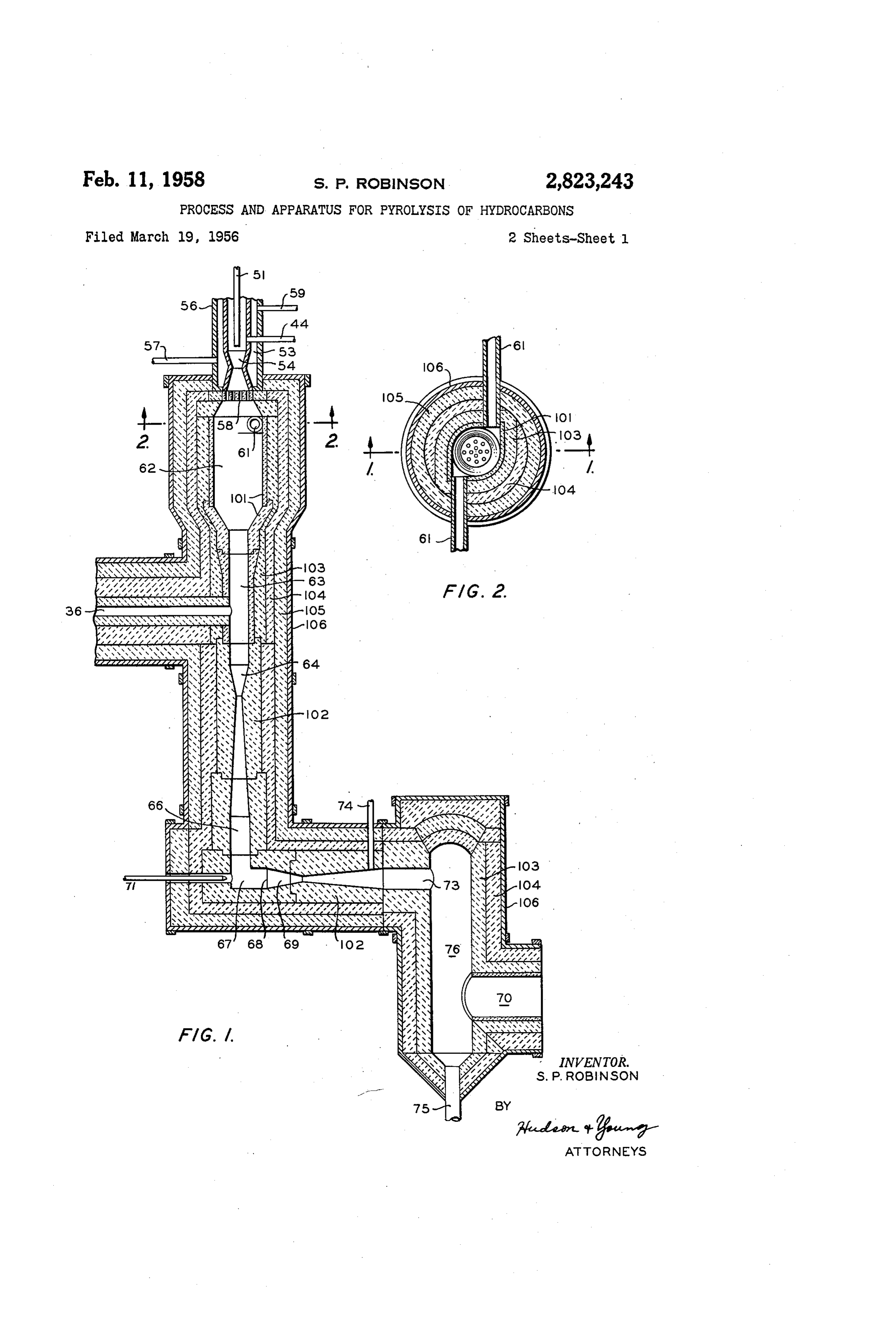
taken on the line 2-2 of Figure 1. Figure 3 is a dia its entire interior wall surface. Inlets 61 are further illus grammatic flow sheet embodying the apparatus illustrated trated in Figure 2.
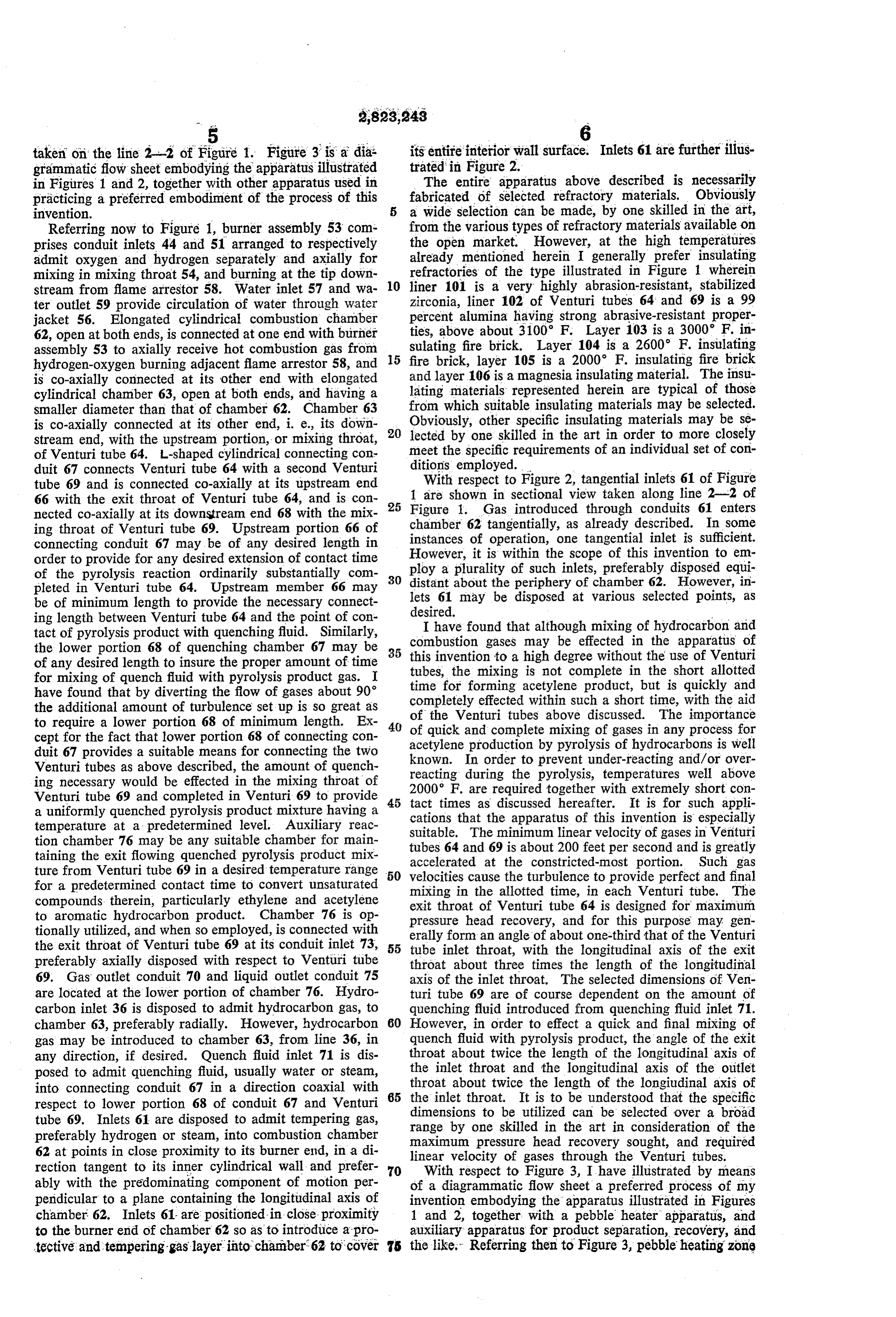
in Figures 1 and 2, together with other apparatus used in The entire apparatus above described is necessarily practicing a preferred embodiment of the process of this fabricated of selected refractory materials. Obviously invention. - - - a wide selection can be made, by one skilled in the art, Referring now to Figure 1, burner assembly 53 com from the various types of refractory materials available on prises conduit inlets 44 and 51 arranged to respectively the open market. However, at the high temperatures admit oxygen and hydrogen separately and axially for already mentioned herein I generally prefer insulating refractories of the type illustrated in Figure 1 wherein mixing in mixing throat 54, and burning at the tip down 10 liner 101 is a very highly abrasion-resistant, stabilized stream from flame arrestor 58. Water inlet 57 and wa ter outlet 59 provide circulation of water through water zirconia, liner 102 of Venturi tubes 64 and 69 is a 99 jacket 56. Elongated cylindrical combustion chamber percent alumina having strong abrasive-resistant proper 62, open at both ends, is connected at one end with burner ties, above about 3100 F. Layer 103 is a 3000 F. in assembly 53 to axially receive hot combustion gas from sulating fire brick. Layer 104 is a 2600°F. insulating hydrogen-oxygen burning adjacent flame arrestor 58, and 5 fire brick, layer 105 is a 2000 F. insulating fire brick is co-axially connected at its other end with elongated and layer 106 is a magnesia insulating material. The insu cylindrical chamber 63, open at both ends, and having a lating materials represented herein are typical of those smaller diameter than that of chamber 62. Chamber 63 from which suitable insulating materials may be selected. is co-axially connected at its other end, i. e., its down Obviously, other specific insulating materials may be se stream end, with the upstream portion, or mixing throat, 20 lected by one skilled in the art in order to more closely of Venturi tube 64. L-shaped cylindrical connecting con meet the specific requirements of an individual set of con duit 67 connects Venturi tube 64 with a second Venturi ditions employed.
tube 69 and is connected co-axially at its upstream end With respect to Figure 2, tangential inlets 61 of Figure 66 with the exit throat of Venturi tube 64, and is con 25 1 are shown in sectional view taken along line 2-2 of nected co-axially at its downstream end 68 with the mix Figure 1. Gas introduced through conduits 61 enters ing throat of Venturi tube 69. Upstream portion 66 of chamber 62 tangentially, as already described. In some connecting conduit 67 may be of any desired length in instances of operation, one tangential inlet is sufficient. However, it is within the scope of this invention to em order to provide for any desired extension of contact time ploy of the pyrolysis reaction ordinarily substantially com 30 a plurality of such inlets, preferably disposed equi pleted in Venturi tube 64. Upstream member 66 may distant about the periphery of chamber 62. However, in be of minimum length to provide the necessary connect lets 61 may be disposed at various selected points, as ing length between Venturi tube 64 and the point of con desired.
tact of pyrolysis product with quenching fluid. Similarly, I have found that although mixing of hydrocarbon and the lower portion 68 of quenching chamber 67 may be 35 this combustion gases may be effected in the apparatus of of any desired length to insure the proper amount of time invention to a high degree without the use of Venturi for mixing of quench fluid with pyrolysis product gas. I tubes, the mixing is not complete in the short allotted have found that by diverting the flow of gases about 90 time for forming acetylene product, but is quickly and the additional amount of turbulence set up is so great as completely effected within such a short time, with the aid to require a lower portion 68 of minimum length. Ex 40 of the Venturi tubes above discussed. The importance of quick and complete mixing of gases in any process for cept for the fact that lower portion 68 of connecting con acetylene production by pyrolysis of hydrocarbons is well duit 67 provides a suitable means for connecting the two known. In order to prevent under-reacting and/or over Venturi tubes as above described, the amount of quench reacting during the pyrolysis, temperatures well above ing necessary would be effected in the mixing throat of 2000 F. are required together with extremely short con Venturi tube 69 and completed in Venturi 69 to provide 45 tact times as discussed hereafter. It is for such appli a uniformly quenched pyrolysis product mixture having a cations that the apparatus of this invention is especially temperature at a predetermined level. Auxiliary reac suitable. The minimum linear velocity of gases in Venturi tion chamber 76 may be any suitable chamber for main tubes 64 and 69 is about 200 feet per second and is greatly taining the exit flowing quenched pyrolysis product mix accelerated at the constricted-most portion. Such gas ture from Venturi tube 69 in a desired temperature range 50 velocities cause the turbulence to provide perfect and final for a predetermined contact time to convert unsaturated mixing in the allotted time, in each Venturi tube. The compounds therein, particularly ethylene and acetylene exit throat of Venturi tube 64 is designed for maximum to aromatic hydrocarbon product. Chamber 76 is op pressure head recovery, and for this purpose may gen tionally utilized, and when so employed, is connected with erally form an angle of about one-third that of the Venturi the exit throat of Venturi tube 69 at its conduit inlet 73, 55 tube inlet throat, with the longitudinal axis of the exit preferably axially disposed with respect to Venturi tube throat about three times the length of the longitudinal 69. Gas outlet conduit 70 and liquid outlet conduit 75 axis of the inlet throat. The selected dimensions of Ven are located at the lower portion of chamber 76. Hydro turi tube 69 are of course dependent on the amount of carbon inlet 36 is disposed to admit hydrocarbon gas, to quenching fluid introduced from quenching fluid inlet 71. chamber 63, preferably radially. However, hydrocarbon 80 However, in order to effect a quick and final mixing of gas may be introduced to chamber 63, from line 36, in quench fluid with pyrolysis product, the angle of the exit any direction, if desired. Quench fluid inlet 71 is dis throat about twice the length of the longitudinal axis of posed to admit quenching fluid, usually water or steam, the inlet throat and the longitudinal axis of the outlet into connecting conduit 67 in a direction coaxial with 65 throat about twice the length of the longiudinal axis of respect to lower portion 68 of conduit 67 and Venturi the inlet throat. It is to be understood that the specific tube 69. Inlets 61 are disposed to admit tempering gas, dimensions to be utilized can be selected over a broad preferably hydrogen or steam, into combustion chamber range by one skilled in the art in consideration of the 62 at points in close proximity to its burner end, in a di maximum pressure head recovery sought, and required linear velocity of gases through the Venturi tubes.
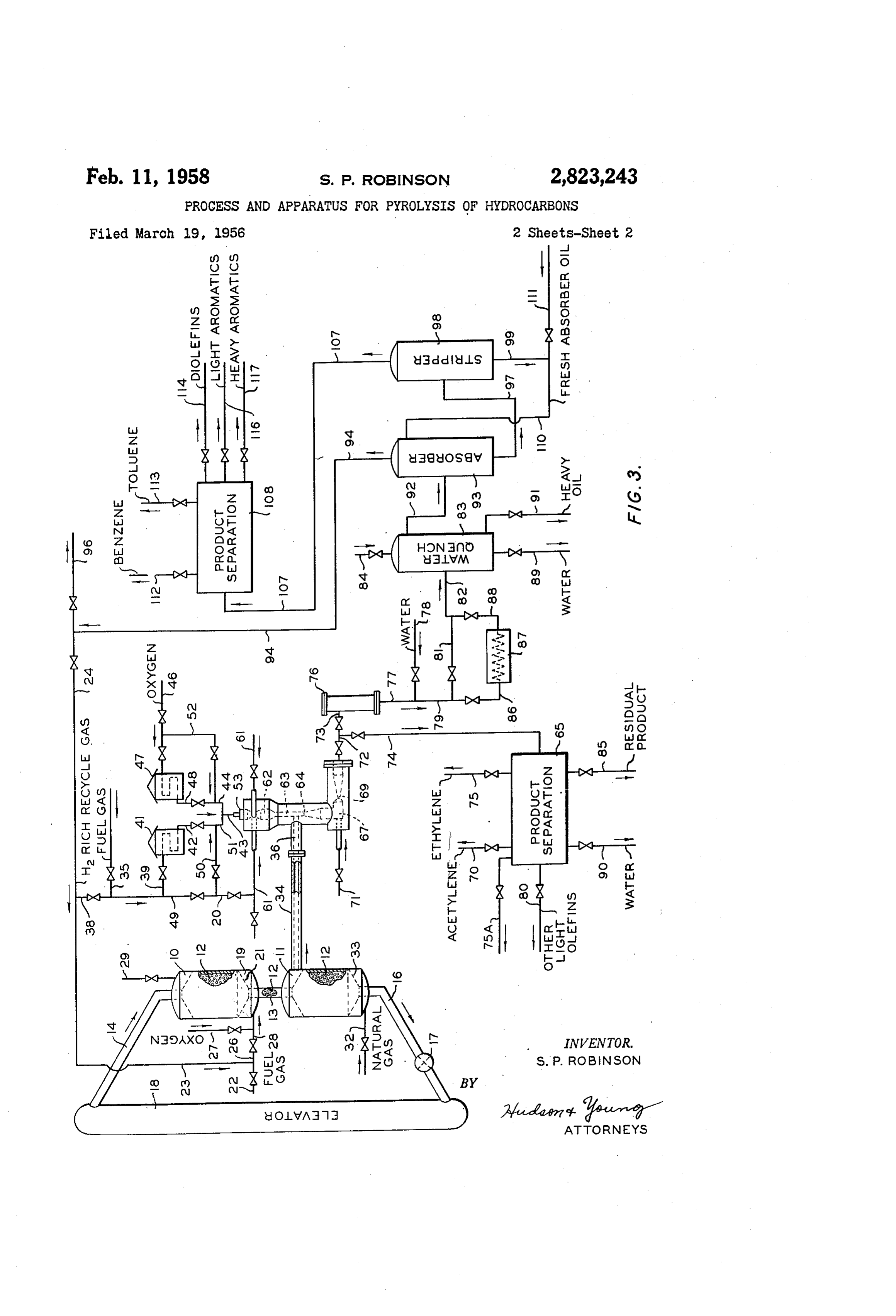
rection tangent to its inner cylindrical wall and prefer With respect to Figure 3, I have illustrated by means ably with the predominating component of motion per of a diagrammatic flow sheet a preferred process of my pendicular to a plane containing the longitudinal axis of invention embodying the apparatus illustrated in Figures chamber 62. Inlets 61 are positioned in close proximity 1 and 2, together with a pebble heater apparatus, and to the burner end of chamber 62 so as to introduce a pro auxiliary apparatus for product separation, recovery, and tective and tempering gas layer into chamber 62 to cover 75 the like," Referring then to Figure 3, pebble heating zone
Page 6
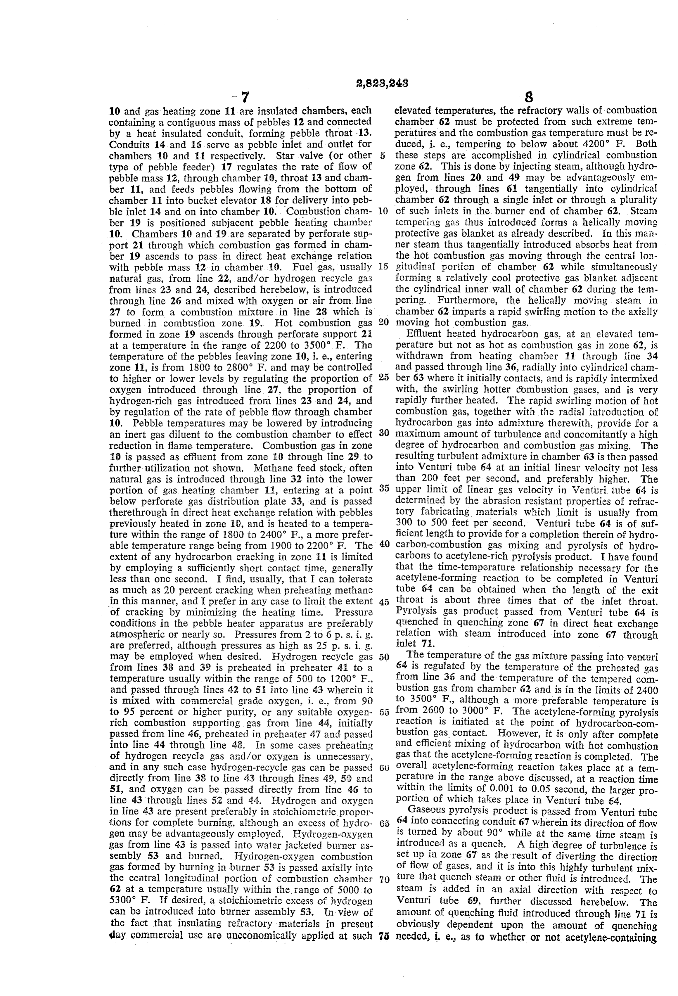
-7 8 10 and gas heating zone 11 are insulated chambers, each elevated temperatures, the refractory walls of combustion containing a contiguous mass of pebbles 12 and connected chamber 62 must be protected from such extreme tem by a heat insulated conduit, forming pebble throat 13. peratures and the combustion gas temperature must be re Conduits 14 and 16 serve as pebble inlet and outlet for duced, i. e., tempering to below about 4200 F. Both chambers 10 and 11 respectively. Star valve (or other these steps are accomplished in cylindrical combustion type of pebble feeder) 17 regulates the rate of flow of Zone 62. This is done by injecting steam, although hydro pebble mass 12, through chamber 10, throat 13 and cham gen from lines 20 and 49 may be advantageously em ber 11, and feeds pebbles flowing from the bottom of ployed, through lines 61 tangentially into cylindrical chamber 11 into bucket elevator 18 for delivery into peb O chamber 62 through a single inlet or through a plurality ble inlet 14 and on into chamber 10... Combustion cham of Such inlets in the burner end of chamber 62. Steam ber 19 is positioned subjacent pebble heating chamber tempering gas thus introduced forms a helically moving 10. Chambers 10 and 19 are separated by perforate Sup protective gas blanket as already described. In this mail port 21 through which combustion gas formed in cham mer steam thus tangentially introduced absorbs heat from ber 19 ascends to pass in direct heat exchange relation the hot combustion gas moving through the central lon with pebble mass 2 in chamber 19. Fuel gas, usually gitudinal portion of chamber 62 while simultaneously
natural gas, from line 22, and/or hydrogen recycle gas forming a relatively cool protective gas blanket adjacent from lines 23 and 24, described herebelow, is introduced the cylindrical inner wall of chamber 62 during the tem through line 26 and mixed with oxygen or air from line pering. Furthermore, the helically moving steam in 27 to form a combustion mixture in line 28, which is chamber 62 imparts a rapid swirling motion to the axially burned in combustion zone 9. Hot combustion gas 20 moving hot combustion gas.
formed in zone 19 ascends through perforate support 2i. Effluent heated hydrocarbon gas, at an elevated tem at a temperature in the range of 2200 to 3500 F. The perature but not as hot as combustion gas in zone 62, is temperature of the pebbles leaving zone 10, i. e., entering withdrawn from heating chamber 11 through line 34 zone 11, is from 1800 to 2800 F. and may be controlled and passed through line 36, radially into cylindrical cham to higher or lower levels by regulating the proportion of 25 ber 63 where it initially contacts, and is rapidly intermixed oxygen introduced through line 27, the proportion of with, the swirling hotter combustion gases, and is very hydrogen-rich gas introduced from lines 23 and 24, and rapidly further heated. The rapid swirling motion of hot by regulation of the rate of pebble flow through chamber combustion gas, together with the radial introduction of 10. Pebble temperatures may be lowered by introducing hydrocarbon gas into admixture therewith, provide for a an inert gas diluent to the combustion chamber to effect 30 maximum amount of turbulence and concomitantly a high reduction in flame temperature. Combustion gas in Zone degree of hydrocarbon and combustion gas mixing. The 0 is passed as effluent from zone to through line 29 to resulting turbulent admixture in chamber 63 is then passed further utilization not shown. Methane feed stock, often into Venturi tube 64 at an initial linear velocity not less natural gas is introduced through line 32 into the lower than 200 feet per second, and preferably higher. The portion of gas heating chamber 1, entering at a point 35 upper limit of linear gas velocity in Venturi tube 64 is below perforate gas distribution plate 33, and is passed determined by the abrasion resistant properties of refrac therethrough in direct heat exchange relation with pebbles tory fabricating materials which limit is usually from previously heated in zone 9, and is heated to a tempera 300 to 500 feet per second. Venturi tube 64 is of suf ture within the range of 1800 to 2400 F., a more prefer ficient length to provide for a completion therein of hydro able temperature range being from 1900 to 2200 F. The 40 carbon-combustion gas mixing and pyrolysis of hydro extent of any hydrocarbon cracking in zone is limited carbons to acetylene-rich pyrolysis product. I have found by employing a sufficiently short contact time, generally that the time-temperature relationship necessary for the less than one second. I find, usually, that I can tolerate acetylene-forming reaction to be completed in Venturi as much as 20 percent cracking when preheating methane tube 64 can be obtained when the length of the exit in this manner, and prefer in any case to limit the extent throat is about three times that of the inlet throat. 'of cracking by minimizing the heating time. Pressure Pyrolysis gas product passed from Venturi tube 64 is conditions in the pebble heater apparatus are preferably quenched in quenching Zone 67 in direct heat exchange atmospheric or nearly so. Pressures from 2 to 6 p.s. i. g. relation with steam introduced into zone 67 through are preferred, although pressures as high as 25 p.s. i.g. ipalet 7.
may be employed when desired. Hydrogen recycle gas The temperature of the gas mixture passing into venturi from lines 38 and 39 is preheated in preheater 4 to a 64 is regulated by the temperature of the preheated gas temperature usually within the range of 500 to 1200° F., from line 35 and the temperature of the tempered com and passed through lines 42 to 5 into line 4:3 wherein it bustion gas from chamber 62 and is in the limits of 2400 is mixed with commercial grade oxygen, i. e., from 90 to 3500. F., although a more preferable temperature is to 95 percent or higher purity, or any suitable oxygen 5 from 2600 to 3000 F. The acetylene-forming pyrolysis rich combustion supporting gas from line 44, initially reaction is initiated at the point of hydrocarbon-com passed from line 46, preheated in preheater 47 and passed bustion gas contact. However, it is only after complete into line 44 through line 43. In some cases preheating and efficient mixing of hydrocarbon with hot combustion of hydrogen recycle gas and/or oxygen is unnecessary, gas that the acetylene-forming reaction is completed. The and in any such case hydrogen-recycle gas can be passed 6) overal acetylene-forming reaction takes place at a tem directly from line 38 to line 43 through lines 49, 5) and Perature in the range above discussed, at a reaction time 51, and oxygen can be passed directly from line 46 to within the limits of 0.001 to 0.05 second, the larger pro line 43 through lines 52 and 44. Hydrogen and oxygen portion of which takes place in Venturi tube 64. in line 43 are present preferably in stoichiometric propor Gaseous pyrolysis product is passed from Venturi tube tions for complete burning, although an excess of hydro 64 into connecting conduit 67 wherein its direction of flow gen may be advantageously employed. Hydrogen-oxygen is turned by about 90° while at the same time steam is gas from line 43 is passed into water jacketed burner as introduced as a quench. A high degree of turbulence is sembly 53 and burned. Hydrogen-oxygen combustion Set up in Zone 67 as the result of diverting the direction gas formed by burning in burner 53 is passed axially into of flow of gases, and it is into this highly turbulent mix the central longitudinal portion of combustion chamber 7) ture that quench steam or other fluid is introduced. The 62 at a temperature usually within the range of 5000 to steam is added in an axial direction with respect to 5300 F. If desired, a stoichiometric excess of hydrogen Venturi tube 69, further discussed herebelow. The can be introduced into burner assembly 53. In view of amount of quenching fluid introduced through line 71 is the fact that insulating refractory materials in present obviously dependent upon the amount of quenching day commercial use are uneconomically applied at such 75 needed, i. e. as to whether or not acetylene-containing
Page 7
pyrolysis product is to be reacted further to form an whereby the rich oil is heated and absorbed materials are aromatic-containing hydrocarbon product discussed more liberated as vapors. Vaporized material is passed through fully hereafter, or free acetylene is to be recovered for line 107 from stripper 98 to product separation means utilization elsewhere. In the latter case water may be 108 comprising coolers, separators, distillation equipment, advantageously used to produce faster cooling to a lower storage tanks and the like not individually illustrated, temperature. In any event, the resulting pyrolysis prod which can be used to effect a separation of various se uct admixture in zone 67 is passed into and through lected product fractions. Lean absorber oil is passed Venturi tube 69 wherein final and complete mixing of from the lower portion of stripper 98 through lines 99 quenching fluid and pyrolysis product is effected. Efflu and 110 to absorber 93. Fresh absorber oil can be in ent quenched gas from Venturi 69 is passed through lines 0 troduced to the absorber system through line 111. Se 72 and 73 to auxiliary reaction chamber 76, or withdrawn lected product fractions separated in zone. 108 include through lines 72 and 74 and passed to separation means benzene withdrawn through line 112, toluene withdrawn 65 for separation and recovery of selected product frac through line 113, cyclopentadiene and other diolefins tions. Separation zone 65 comprises various types of withdrawn through line 114, and a fraction containing well-known product recovery equipment, not individually 5 light aromatic hydrocarbons such as styrene, methylsty illustrated, especially suitable for recovering selected rene, and xylenes, withdrawn through line 116. A rela fractions from the material admitted from line 74, such tively heavy fraction of aromatics comprising naph as distillation, solvent extraction, absorption, settling stor thalene, anthracene and other, heavier aromatics and/or age, and the like. Selected product fractions separated in tars is withdrawn through line 117. zone 65 include light gases (e. g. H2), acetylene, ethylene, 20 During the non-process periods or when starting up, and other light olefins, or diolefins, together with residual natural gas is introduced into the water cooled burner carbonaceous by-product and water which are withdrawn after through lines 35, 49 and 50 and burned with oxygen, and respectively from zone 65 through lines 75A, 70, 75, 80, pyrolysis is under way, the natural gas feed to the 85, and 90. In the latter case effluent gas from Venturi burner is replaced with the recycle hydrogen stream. tube 69 is quenched to a temperature below that at which 25 Fresh hydrogen may be introduced into the burner sys acetylene and/or ethylene in the pyrolysis product further tem through line 30, when desired. reacts appreciably to form polymer or to form carbon and For convenience and clarity certain apparatus such as hydrogen, which temperature is preferably below about pumps, surge tanks, accumulators, valves, etc. have not been shown in the drawing. Obviously such modifica
However, I often prefer to pass the quenched pyrolysis 30 tions of the present invention may be practiced without product from Venturi tube 69 to aromatics-forming cham departing from the scope of the invention. ber 76 for the conversion of unsaturated pyrolysis prod in As already described, a feature of my invention resides the formation of aromatic hydrocarbons from acetyl uct, particularly the acetylene and ethylene components, to an aromatic hydrocarbon-containing product. When ene at temperatures from 600 to 1000* F. above those ordinarily employed, and the advantages of this higher operating in this manner, the amount of quenching steam 35 temperature introduced through line 71 is regulated to cool the pyrol operation have already been pointed out. ysis product to an aromatics-forming temperature within I am able to utilize such high aromatic-forming, tempera the range of 1800 to 2300 F. tures by operating in the presence of hydrogen. Under In aromatics-forming chamber 76, pyrolysis product such conditions, dehydrogenation of acetylene with con from Venturi tube 69 is maintained at its existing tem 40 sequent carbon formation, and hydrogenation of acetylene to ethane with consequent low yields of desired product perature (1800 to 2300 F.) for a duration of from 0.05 to 5.0 seconds to form predominantly light aromatic hy is substantially prevented, and higher and more efficient drocarbons, particularly benzene and toluene together conversions of acetylene are obtained. Some hydrogen with relatively small amounts of diolefin hydrocarbons 45 ation of acetylene to ethylene may occur, but if so, it is and heavier aromatic hydrocarbons formed as by-product. in no way disadvantageous. The temperature conditions I prefer usually to quench acetylene-containing pyrolysis are chosen such that partial hydrogenation to ethylene is product in zone 67 so that gases enter chamber 76 at a possible and favorable, but at which total hydrogenation temperature in a preferred range of 1900 to 2200 F., of acetylene to ethane or of any ethylene to ethane, is and under such conditions a contact time within the limits 50 not promoted. The contact time is so chosen that dehy
Effluent from zone 76 is passed through line 77 and drogenation of acetylene, and polymerization of acetylene quenched to a temperature in the range of about 400 to issuchkeptas atbutadiene, a minimum, and so chosen that unsaturates cyclopentadiene, and Cs dienes are 800 F. by admixture in line 79 with water spray intro duced through line 78. The resulting admixture is passed 55 carbons particularly, high formed together with yields of light aromatic hydro through lines 81 and 82 to water quench tower 83 wherein amounts of heavier aromatic and benzene toluene. Only minor components, tars and the it is contacted countercurrently with water introduced through line 84 and cooled to a temperature usually like are formed at these selected temperatures and contact within the range of 100 to 200 F. If desired, material times. Typical of preferred time-temprature relationships in line 79 may first be passed through line 86, cooler 87, employed in the practice of the aromatics-forming step of and line 88 to line 82, with or without water introduced 60 my invention are indicated as follows: through line 78. Water may be drained from zone 83 Temp., ° F. through line 89, and any heavy by-product oils removed Time, sec.:
through line 91. Product-containing gas is passed from 1.5 to 5.0"------------------------------- 1800 zone 83: through line 92 to an absorber-stripper system, 1.0?? 3.0 ------------1900
preferably of the conventional type employing a mineral 65 0 6: to 2.0 ????? ??? ?? ------------------------- ? - 2000 · seal oil absorbent. Material in line 92 is introduced to ab 0.4 to 1.2 . ??? . .. . sorber 93 and passed therein countercurrently in relation 0.6-to-0.2 ???? - - - - - . .. . .
to down-flowing fresh and/or stripped mineral seal oil in 0.05to 0.2 ?? ?---?---?--:----------------------------- 2300 troduced through line 110. Hydrogen-rich gas is passed from an upper portion of absorber 93 through line: 94 I am not certain as to the exact mechanism of the re for combustion in zone 19 and/or burner 53. Any ex action taking place in the aromatics-forming step. How cess recycle gas in line 94 may be withdrawn through ever, it is possible that (1) acetylene is first partially hy line 96. Enriched absorber oil is passed through the drogenated to ethylene as indicated by the equation lower portion of zone 93 through line 97 and introduced into stripper 98 maintained under distillation conditions 75 ?CH +H CH
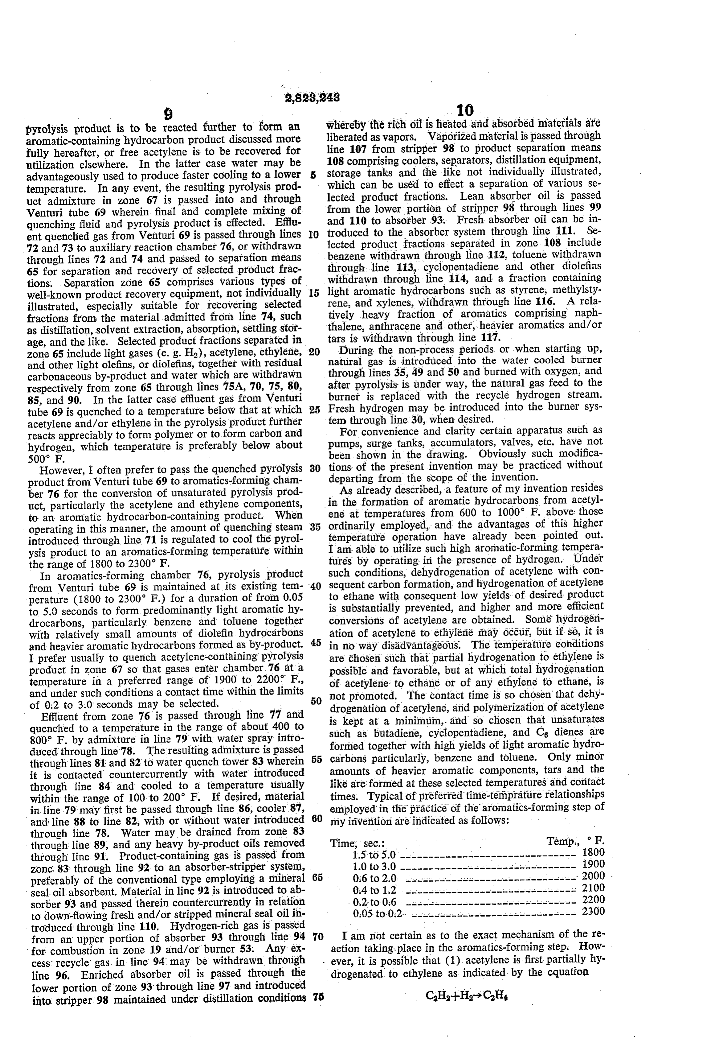
Page 8
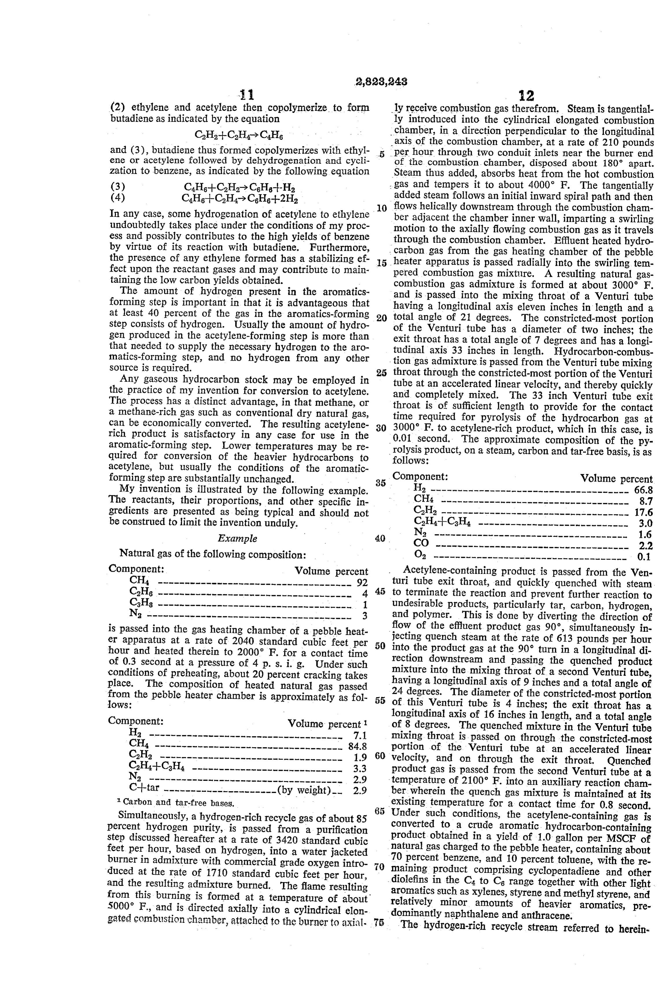
(2) ethylene and acetylene then copolymerize to form ly receive combustion gas therefrom. Steam is tangential butadiene as indicated by the equation ly introduced into the cylindrical elongated combustion chamber, in a direction perpendicular to the longitudinal and (3), butadiene thus formed copolymerizes with ethyl axis of the combustion chamber, at a rate of 210 pounds ene or acetylene followed by dehydrogenation andi cycli per hour through two conduit inlets near the burner end of the combustion chamber, disposed about 180 apart.
zation to benzene, as indicated by the following equation Steam thus added, absorbs heat from the hot combustion gas and tempers it to about 4000 F. The tangentially added steam follows an initial inward spiral path and then 10 flows helically downstream through the combustion cham
In any case, some hydrogenation of acetylene to ethylene undoubtedly takes place under the conditions of my proc ber adjacent the chamber inner wall, imparting a Swirling ess and possibly contributes to the high yields of benzene through tothethecombustion motion axially flowing combustion gas as it travels by virtue of its reaction with butadiene. Furthermore, carbon gas from the gaschamber. Effluent heated hydro the presence of any ethylene formed has a stabilizing ef 15 heater apparatus is passed radially into the ofSwirling heating chamber the pebble fect upon the reactant gases and may contribute to main pered combustion gas mixture. A resulting natural tem gas taining the low carbon yields obtained. combustion gas admixture is formed at about 3000 F. The amount of hydrogen present in the aromatics forming step is important in that it is advantageous that and is passed into the mixing throat of a Venturi tube having a longitudinal axis eleven inches in length and a at least 40 percent of the gas in the aromatics-forming 20 total step consists of hydrogen. Usually the amount of hydro of theangle of 21 degrees. The constricted-most portion gen produced in the acetylene-forming step is more than exit throat has atube
Venturi has a diameter of two inches; the total angle of 7 degrees and has a longi that needed to supply the necessary hydrogen to the aro tudinal axis 33 inches in length. Hydrocarbon-combus matics-forming step, and no hydrogen from any other ...tion gas admixture is passed from the Venturi tube mixing source is required.
Any gaseous hydrocarbon stock may be employed in 25 throattube at through the constricted-most portion of the Venturi an accelerated linear velocity, and thereby quickly the practice of my invention for conversion to acetylene. and completely mixed. The 33 inch Venturi tube exit The process has a distinct advantage, in that methane, or throat is of sufficient length to provide for the contact a methane-rich gas such as conventional dry natural gas, can be economically converted. The resulting acetylene 30 time
required for pyrolysis of the hydrocarbon gas at
F. to acetylene-rich product, which in this case, is rich product is satisfactory in any case for use in the 0.01 second. The approximate composition of the py aromatic-forming step. Lower temperatures may be re rolysis product, on a steam, carbon and tar-free basis, is as quired for conversion of the heavier hydrocarbons to follows:
acetylene, but usually the conditions of the aromatic forming step are substantially unchanged. 35 Component: Volume percent My invention is illustrated by the following example. H2 ------------------------------------- 66.8 The reactants, their proportions, and other specific in CH4 ----------------------------------- 8.7 gredients are presented as being typical and should not C2H2 ----------------------------------- 17.6 be construed to limit the invention unduly. LS?C
H4-H-C3H4 -------------------SS SS SSLS LSSL LSSLS S SLS S S SLS LS 3.0
Example 40 N2 ------------------------------------ 1.6
Natural gas of the following composition: O2 ------------------------------------ 0.1 Component: Volume percent Acetylene-containing product is passed from the Ven CH4 ------------------------------------ 92 45 turi tube exit throat, and quickly quenched with steam C2H6 ------------------------------------ 4 to terminate the reaction and prevent further reaction to C3H8 ------------------------------------ 1. undesirable products, particularly tar, carbon, hydrogen, Na --??---?------------------------------ 3 and polymer. This is done by diverting the direction of flow of the effluent product gas 90°, simultaneously in er apparatus at a rate of 2040 standard cubic feet per 50 jecting quench steam at the rate of 613 pounds per hour hour and heated therein to 2000 F. for a contact time into the product gas at the 90° turn in a longitudinal di of 0.3 second at a pressure of 4 p. s. i. g. Under such rection downstream and passing the quenched product conditions of preheating, about 20 percent cracking takes mixture into the mixing throat of a second Venturi tube, place. The composition of heated natural gas passed having a longitudinal axis of 9 inches and a total angle of from the pebble heater chamber is approximately as fol 55 24 degrees. The diameter of the constricted-most portion lows: of this Venturi tube is 4 inches; the exit throat has a Component: Volume percent longitudinal axis of 16 inches in length, and a total angle of 8 degrees. The quenched mixture in the Venturi tube
Ha ------------------------------------ 7.1 mixing throat is passed on through the constricted-most CH4 ----------------------------------- 84.8 portion of the Venturi tube at an accelerated linear C2H2 ---------------------------------- 1.9 60 velocity, and on through the exit throat. Quenched C2H4+C3H4 ---------------------------- 3.3 product gas is passed from the second Venturi tube at a Na ------------------------------------ 2.9 temperature of 2100 F. into an auxiliary reaction cham Citar --------------------- (by weight)- 2.9 ber, wherein the quench gas mixture is maintained at its Carbon and tar-free bases. existing temperature for a contact time for 0.8 second. 85 Under such conditions, the acetylene-containing gas is
Simultaneously, a hydrogen-rich recycle gas of about 85 percent hydrogen purity, is passed from a purification converted to a crude aromatic hydrocarbon-containing step discussed hereafter at a rate of 3420 standard cubic product obtained in a yield of 1.0 gallon per MSCF of feet per hour, based on hydrogen, into a water jacketed natural gas charged to the pebble heater, containing about 70 percent benzene, and 10 percent toluene, with the re burner in admixture with commercial grade oxygen intro 0 maining duced at the rate of 1710 standard cubic feet per hour, diolefins in product comprising cyclopentadiene and other and the resulting admixture burned. The flame resulting aromatics Such the C4 to C6 range together with other light from this burning is formed at a temperature of about relatively minor as xylenes, styrene and methylstyrene, and 5000 F., and is directed axially into a cylindrical elon dominantly naphthalene amounts of heavier aromatics, pre and anthracene.
gated combustion chamber, attached to the burner to axial. 75 The hydrogen-rich recycle stream referred to herein
Page 9
above is recovered from the product mixture in the said admixture in a high state of turbulence for a contact auxiliary recovery equipment and is recycled to the burn time within the range of from 0.001 to 0.05 second, ing step above described. This hydrogen-rich recycle gas whereby acetylene and ethylene-containing hydrocarbon has the following approximate composition. pyrolysis product is formed, introducing quenching fluid Component: Volume percent in a predetermined amount into said pyrolysis product to quench same to a temperature below about 500 F.
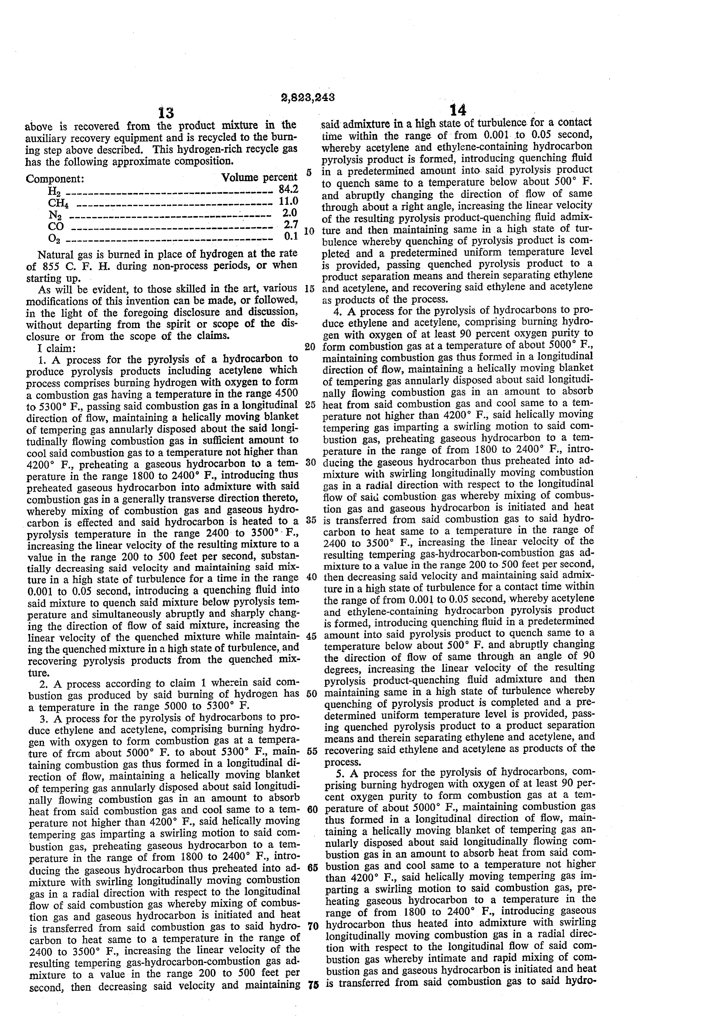
*2 ------------------------------------- 84.2 and abruptly changing the direction of flow of same CH4 ----------------------------------- 11.0 through about a right angle, increasing the linear velocity N2 ------------------------------------ 2.0 of the resulting pyrolysis product-quenching fluid admix CO ------------------------------------ 2.7 0 ture and then maintaining same in a high state of tur Oa ------------------------------------- 0.1 bulence whereby quenching of pyrolysis product is com Natural gas is burned in place of hydrogen at the rate pleted and a predetermined uniform temperature level of 855 C. F. H. during non-process periods, or when is provided, passing quenched pyrolysis product to a starting up. product separation means and therein separating ethylene As will be evident, to those skilled in the art, various 5 and acetylene, and recovering said ethylene and acetylene modifications of this invention can be made, or followed, as products of the process.
in the light of the foregoing disclosure and discussion, duce 4. A process for the pyrolysis of hydrocarbons to pro without departing from the spirit or scope of the dis ethylene and acetylene, comprising burning hydro closure or from the scope of the claims. gen with oxygen of at least 90 percent oxygen purity to I claim: 20 form combustion gas at a temperature of about 5000 F., 1. A process for the pyrolysis of a hydrocarbon to maintaining combustion gas thus formed in a longitudinal produce pyrolysis products including acetylene which direction of flow, maintaining a helically moving blanket process comprises burning hydrogen with oxygen to form of tempering gas annularly disposed about said longitudi a combustion gas having a temperature in the range 4500 nally flowing combustion gas in an amount to absorb to 5300 F., passing said combustion gas in a longitudinal heat from said combustion gas and cool same to a tem direction of flow, maintaining a helically moving blanket perature not higher than 4200 F., said helically moving of tempering gas annularly disposed about the said longi tempering gas imparting a swirling motion to said com tudinally flowing combustion gas in sufficient amount to bustion gas, preheating gaseous hydrocarbon to a tem cool said combustion gas to a temperature not higher than perature in the range of from 1800 to 2400 F., intro 4200 F., preheating a gaseous hydrocarbon to a tem 30 ducing the gaseous hydrocarbon thus preheated into ad perature in the range 1800 to 2400 F., introducing thus mixture with swirling longitudinally moving combustion preheated gaseous hydrocarbon into admixture with said gas in a radial direction with respect to the longitudinal combustion gas in a generally transverse direction thereto, flow of said combustion gas whereby mixing of combus whereby mixing of combustion gas and gaseous hydro tion gas and gaseous hydrocarbon is initiated and heat carbon is effected and said hydrocarbon is heated to a 35 is transferred from said combustion gas to said hydro pyrolysis temperature in the range 2400 to 3500. F., carbon to heat same to a temperature in the range of increasing the linear velocity of the resulting mixture to a 2400 to 3500 F., increasing the linear velocity of the value in the range 200 to 500 feet per second, substan resulting tempering gas-hydrocarbon-combustion gas ad tially decreasing said velocity and maintaining said mix mixture to a value in the range 200 to 500 feet per second, ture in a high state of turbulence for a time in the range 40 then decreasing said velocity and maintaining said admix 0.001 to 0.05 second, introducing a quenching fluid into ture in a high state of turbulence for a contact time within said mixture to quench said mixture below pyrolysis tem the range of from 0.001 to 0.05 second, whereby acetylene perature and simultaneously abruptly and sharply chang and ethylene-containing hydrocarbon pyrolysis product ing the direction of flow of said mixture, increasing the is formed, introducing quenching fluid in a predetermined linear velocity of the quenched mixture while maintain 45 amount into said pyrolysis product to quench same to a ing the quenched mixture in a high state of turbulence, and temperature below about 500 F. and abruptly changing recovering pyrolysis products from the quenched mix the direction of flow of same through an angle of 90 ture. degrees, increasing the linear velocity of the resulting 2. A process according to claim 1 wherein said com pyrolysis product-quenching fluid admixture and then bustion gas produced by said burning of hydrogen has 50 maintaining same in a high state of turbulence whereby a temperature in the range 5000 to 5300' F. quenching of pyrolysis product is completed and a pre 3. A process for the pyrolysis of hydrocarbons to pro determined uniform temperature level is provided, pass duce ethylene and acetylene, comprising burning hydro ing quenched pyrolysis product to a product separation gen with oxygen to form combustion gas at a tempera means and therein separating ethylene and acetylene, and ture of from about 5000 F. to about 5300' F., main 55 recovering said ethylene and acetylene as products of the taining combustion gas thus formed in a longitudinal di proceSS.
rection of flow, maintaining a helically moving blanket 5. A process for the pyrolysis of hydrocarbons, com of tempering gas annularly disposed about said longitudi prising burning hydrogen with oxygen of at least 90 per nally flowing combustion gas in an amount to absorb cent oxygen purity to form combustion gas at a tem heat from said combustion gas and cool same to a tem 60 perature of about 5000 F., maintaining combustion gas perature not higher than 4200 F., said helically moving thus formed in a longitudinal direction of flow, main tempering gas imparting a swirling motion to said com taining a helically moving blanket of tempering gas an bustion gas, preheating gaseous hydrocarbon to a tem nularly disposed about said longitudinally flowing com perature in the range of from 1800 to 2400 F., intro bustion gas in an amount to absorb heat from said com bustion gas and cool same to a temperature not higher ducing the gaseous hydrocarbon thus preheated into ad 65 than 4200° F., said helically moving tempering gas im mixture with swirling longitudinally moving combustion parting a swirling motion to said combustion gas, pre gas in a radial direction with respect to the longitudinal heating gaseous hydrocarbon to a temperature in the flow of said combustion gas whereby mixing of combus range of from 1800 to 2400 F., introducing gaseous tion gas and gaseous hydrocarbon is initiated and heat is transferred from said combustion gas to said hydro 70 hydrocarbon thus heated into admixture with swirling longitudinally moving combustion gas in a radial direc carbon to heat same to a temperature in the range of tion with respect to the longitudinal flow of said com 2400 to 3500 F., increasing the linear velocity of the bustion gas whereby intimate and rapid mixing of com resulting tempering gas-hydrocarbon-combustion gas ad mixture to a value in the range 200 to 500 feet per bustion gas and gaseous hydrocarbon is initiated and heat second, then decreasing said velocity and maintaining 75 is transferred from said combustion gas to said hydro
Page 10
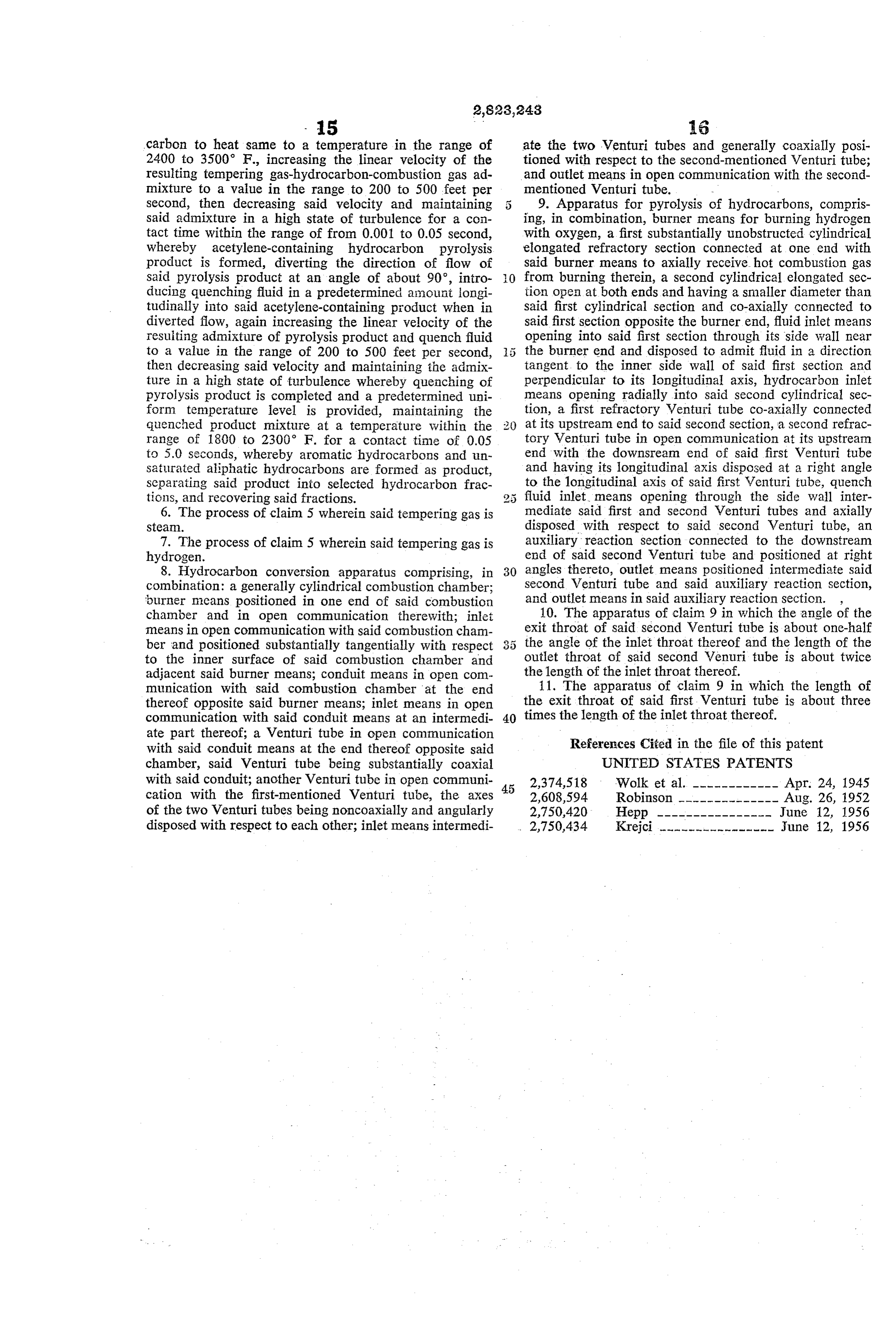
- 15 6 carbon to heat same to a temperature in the range of ate the two Venturi tubes and generally coaxially posi 2400 to 3500 F., increasing the linear velocity of the tioned with respect to the second-mentioned Venturi tube; resulting tempering gas-hydrocarbon-combustion gas ad and outlet means in open communication with the second mixture to a value in the range to 200 to 500 feet per mentioned Venturi tube. -
Second, then decreasing said velocity and maintaining 5 9. Apparatus for pyrolysis of hydrocarbons, compris Said admixture in a high state of turbulence for a con ing, in combination, burner means for burning hydrogen tact time within the range of from 0.001 to 0.05 second, with oxygen, a first substantially unobstructed cylindrical whereby acetylene-containing hydrocarbon pyrolysis elongated refractory section connected at one end with product is formed, diverting the direction of flow of said burner means to axially receive hot combustion gas said pyrolysis product at an angle of about 90°, intro from burning therein, a second cylindrical elongated sec ducing quenching fluid in a predetermined amount longi tion open at both ends and having a smaller diameter than tudinally into said acetylene-containing product when in said first cylindrical section and co-axially cennected to diverted flow, again increasing the linear velocity of the said first section opposite the burner end, fluid inlet means resuiting admixture of pyrolysis product and quench fluid opening into said first section through its side wall near to a value in the range of 200 to 500 feet per second, the burner end and disposed to admit fluid in a direction then decreasing said velocity and maintaining the admix tangent to the inner side wall of said first section and ture in a high state of turbulence whereby quenching of perpendicular to its longitudinal axis, hydrocarbon inlet pyrolysis product is completed and a predetermined uni means opening radially into said second cylindrical sec form temperature level is provided, maintaining the tion, a first refractory Venturi tube co-axially connected quenched product mixture at a temperature within the at its upstream end to said second section, a second refrac range of 1800 to 2300 F. for a contact time of 0.05 tory Venturi tube in open communication at its upstream to 5.0 Seconds, whereby aromatic hydrocarbons and un end with the downsream end of said first Venturi tube Saturated aliphatic hydrocarbons are formed as product, and having its longitudinal axis disposed at a right angle Separating said product into selected hydrocarbon frac to the longitudinal axis of said first Wenturi tube, quench tions, and recovering said fractions. fluid inlet means opening through the side wall inter 6. The process of claim 5 wherein said tempering gas is mediate said first and second Venturi tubes and axially Stean. disposed with respect to said second Venturi tube, an 7. The process of claim 5 wherein said tempering gas is auxiliary reaction section connected to the downstream hydrogen. end of said second Venturi tube and positioned at right 8. Hydrocarbon conversion apparatus comprising, in 30 angles thereto, outlet means positioned intermediate said combination: a generally cylindrical combustion chamber; second Venturi tube and said auxiliary reaction section, 'burner means positioned in one end of said combustion and outlet means in said auxiliary reaction section. , chamber and in open communication therewith; inlet 10. The apparatus of claim 9 in which the angle of the means in open communication with said combustion cham exit throat of said second Wenturi tube is about one-half ber and positioned substantially tangentially with respect 3 5 the angle of the inlet throat thereof and the length of the to the inner surface of said combustion chamber and outlet throat of said second Wenuri tube is about twice adjacent Said burner means; conduit means in open com the length of the inlet throat thereof. munication with said combustion chamber at the end 11. The apparatus of claim 9 in which the length of thereof opposite said burner means; inlet means in open the exit throat of said first Venturi tube is about three communication with said conduit means at an intermedi 40 times the length of the inlet throat thereof. ate part thereof; a Venturi tube in open communication with said conduit means at the end thereof opposite said References (Cited in the file of this patent chamber, said Venturi tube being substantially coaxial UNITED STATES PATENTS with said conduit; another Venturi tube in open communi 2,374,518 Wolk et al. ———————————— Apr. 24, 1945 cation with the first-mentioned Venturi tube, the axes 45 2,608,594 Robinson -------------- Aug. 26, 1952 of the two Venturi tubes being noncoaxially and angularly 2,750,420 Hepp ---------------- June 12, 1956 disposed with respect to each other; inlet means intermedi 2,750,434 Krejci ---------------- June 12, 1956
Page 11
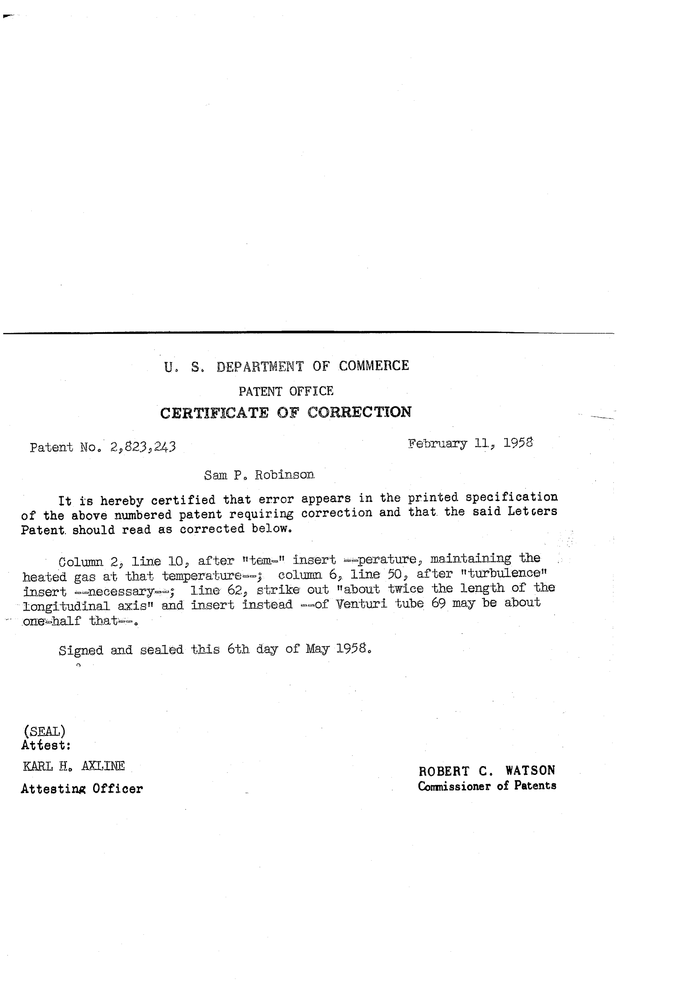
U. S. EPARTMENT OF COMMERCE
PATENT OFFICE
CERTFICATE OF CORRECTION
Patent No. 2,823,243 February Il 1958 Sam P. Robinson
It is hereby certified that error appears in the printed specification of the above numbered patent requiring correction and that the said Let Gers Patent. should read as corrected below.
Column 2, line 10, after tem-" insert ==perature, maintaining the heated gas at that temperature-le; column 6 line 50 after turbulence? insert e-necessary-se; line 62 strike out "about twice the length of the longitudinal axis" and insert instead --of Venturi tube 69 may be about
Signed and Sealed this 6th day of May 1958.
(SEAL)
Attest:
KARI, H, AXLINE ROBERT C. WATSON Attesting Officer Commissioner of Patents
Provenance
- Collection
- Cited prior art
- Original PDF
- patentimages.storage.googleapis.com →
- Filed
- 1956-03-19
- Pages
- 11
- Method
- pdftotext (the PDF's own text layer) + pdftoppm 300dpi page scans
- Source
- Google Patents bibliographic record
- Granted
- 1958-02-11
- Inventors
- Sam P Robinson; Phillips Petroleum Co
- Transcribed from
- patentimages.storage.googleapis.com →