patent · US4158614
Method for separating gaseous mixtures of matter
19 June 1979
Page 1 — bibliographic record
United States Patent 19 (11) 4,158,614 Schuster et al. 45 Jun. 19, 1979 54 METHOD FOR SEPARATING GASEOUS (56) References Cited MIXTURES OF MATTER U.S. PATENT DOCUMENTS 75 Eberhard Schuster; Arno Kersting,
Inventors: 3,951,768 4/1976 Gurs ............................ 204/DIG. 11 both of Erlangen, Fed. Rep. of
Germany Primary Examiner-Howard S. Williams 73) Assignee: Kraftwerk Union Aktiengeselischaft, Attorney, Agent, or Firm-Kenyon & Kenyon Mülheim, Fed. Rep. of Germany
Molecules to be separated from a mixture of matter of a 22 Filed: Apr. 14, 1977 chemical component are excited in a manner known per se by narrow-band light sources, and a chemical reac
Related U.S. Application Data tion partner for reacting with these molecules is ad (63) Continuation of Ser. No. 573,071, Apr. 30, 1975, mixed while supplied with energy by electromagnetic abandoned. radiation or heating, and as additionally required for (51) Int. C.2 ..... a as see wop ow own on 0 0 e o 8 de B01 1/10 making chemical reactions possible.
(52) U.S. C. ..... - - - - - - - - - - 204/157.1 R; 204/DIG. 11 (58) Field of Search ................................ 204/DIG. 11 7 Claims, 4 Drawing Figures
19- | 14 -15
Page 2
Drawing sheet — no readable text.
Page 3
Drawing sheet — no readable text.
Page 4
cal reaction, in a different manner to make the deisred
METHOD FOR SEPARATING GASEOUS chemical reaction possible. This amount of energy is MXTURES OF MATTER here apportioned so that only excited molecules of the one isotope react with this reaction partner, but not the .
This is a continuation of application Ser. No. 573,071 5 unexcited molecules of the other isotopes or substances. filed April 30, 1975 now abandoned. To obtain the highest possible separation yield, the BACKGROUND OF THE INVENTION reaction partnershould here be present in excess, so that the molecular impacts necessary for the chemical reac
The present invention concerns a method for chemi tion, take place more between the reaction partners and cally separating gaseous mixtures of matter and particu 10 less between the molecules of the mixture of isotopes or larly isotopes, using laser beams to make possible a matter. In the latter case, the energy supplied would directed chemcial reaction of a mixture component, largely get lost for the separation effect and the separa with a chemical reaction partner.
It is known that molecules which are composed of at tionTheeffect itself would become poorer. additional energy for the reaction partner can be least two different elements, absorb electromagnetic 15 supplied in different ways, e.g., by heating it before it is radiation in the infrared region. The infrared absorption introduced into the separation chamber or by supplying spectra reflects the structure of the molecules, and are energy within the separating device by means of lasers, caused by the energy transitions of the rotation-vibra infrared light sources, ultraviolet light sources etc. tional states. As the vibration energy of a molecule Although the feasibility of this method of separation depends greatly on the mass of the participating atoms, 20 is not limited to specific mixtures of isotopes or matter, molecules which contain one kind of element with dif ferent isotopes, also have different spectra-scopically its particular importance is in the field of nuclear tech detectable absorption lines.This difference in infrared nology. Here, it is particularly the separation of the absorption can be used for isotope separation or more uranium isotopes U238 and U235, such as is required generally speaking, for the separation of matter, if the 25 for the enrichment of the nuclear fuel with fissionable infrared emission line of a laser is brought into reso uranium 235 for the different reactor types to different nance with the rotation vibration line of the respective degrees. The methods used heretofore of gas diffusion molecule of the kind of atom to be separated, so the or the ultracentrifuge require extremely large technical molecule is excited thereby. The molecule excited in means and in addition, consume an extremely large this manner can then be made to react from its higher 30 amount of energy. These drawbacks are no longer in energy level thus imparted, with suitable partners. In herent in the method according to the invention. other words, the absorption of a light quantum by such As already mentioned, a suitable reaction partner is a molecule constitutes a supply of energy which, with also necessary for carrying out this method. For the regard to the initiation of certain chemical reactions, separation of the uranium isotopes, the following reac has a similar effect as, for instance, an increase in tem 35 tions can be used, for instance, from which the starting perature. partners as well as the chemical reaction partners can be According to this principle, a mixture of methanol See:
and deuterized methanol has already been separated by bromination of the normal methanol, for which see
"Applied Physics Letters', vol. 17, no. 12, pages 516 to 40 519. According to the same principle, the separation of uranium isotopes in furthermore proposed in the (Ger man) Offenlegungsschrift No. 1,959,767 of June 3, 1971. 2 UFs-- Sicil- UF --SiF-2 Cl The implementation of this known method for iso tope separation, however, hangs on three conditions; 45 O first, laser arrangements must be available which can be tuned to the desired molecular vibration frequencies; UF6+2 HC-UF4-2 HF secondly, the energy of this radiation must be great enough to that the chemical reaction can be released, O and third, the reaction partner must be chosen so that a 50 separation of the newly generated mixture of matter in a reaction apparatus is possible. However, as in the infrared region the energy which can be supplied, for As a further example from nuclear reactor technol instance by means of lasers, is relatively small, the feasi ogy, the separation of boron isotopes should be men bility of the above known method is very limited. 55 tioned, with the following chemical reaction: The problem therefore exists to further develop this known method in such a way that such energy limita tions are less important.
SUMMARY OF THE INVENTION
All these reactions proceed normally only at elevated 60 temperature. Through the specific excitation of definite
According to the invention, a solution of the above uranium or boron isotopes, the chemical reaction takes problem is achieved by exciting the molecules of the place only between the latter; the other isotope com matter to be separated in the manner known per se by pounds remain untouched.
means of narrow-band light sources, and by supplying to the other reaction partner additional energy as re 65 BRIEF DESCRIPTION OF THE DRAWINGS quired to make the chemical reaction possible. Contrary The accompanying drawings schematically illustrate to the method described previously, energy is supplied examples of apparatus for carrying out the present in therefore to the reaction partner required for the chemi vention, the various figures being as follows:
Page 5
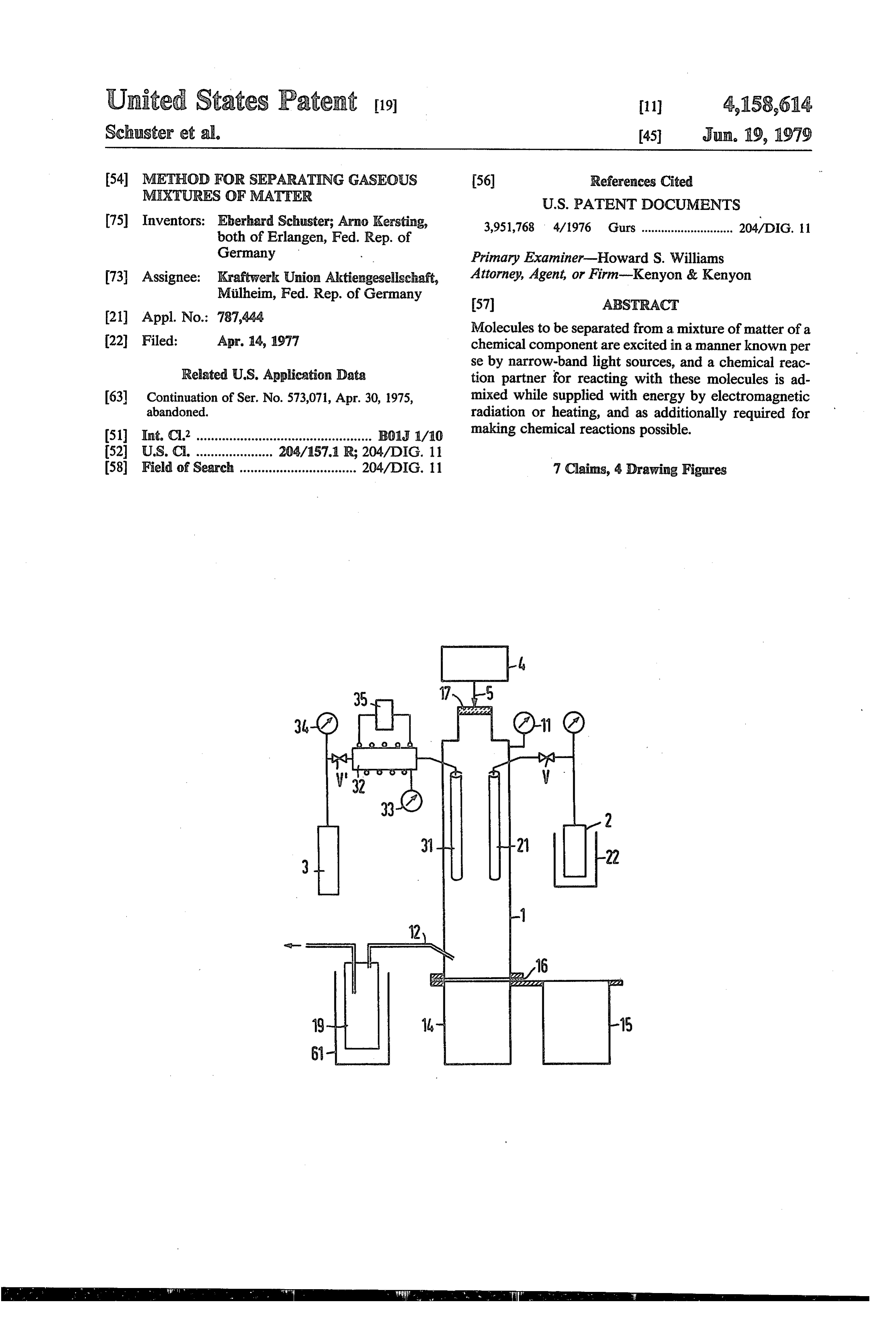
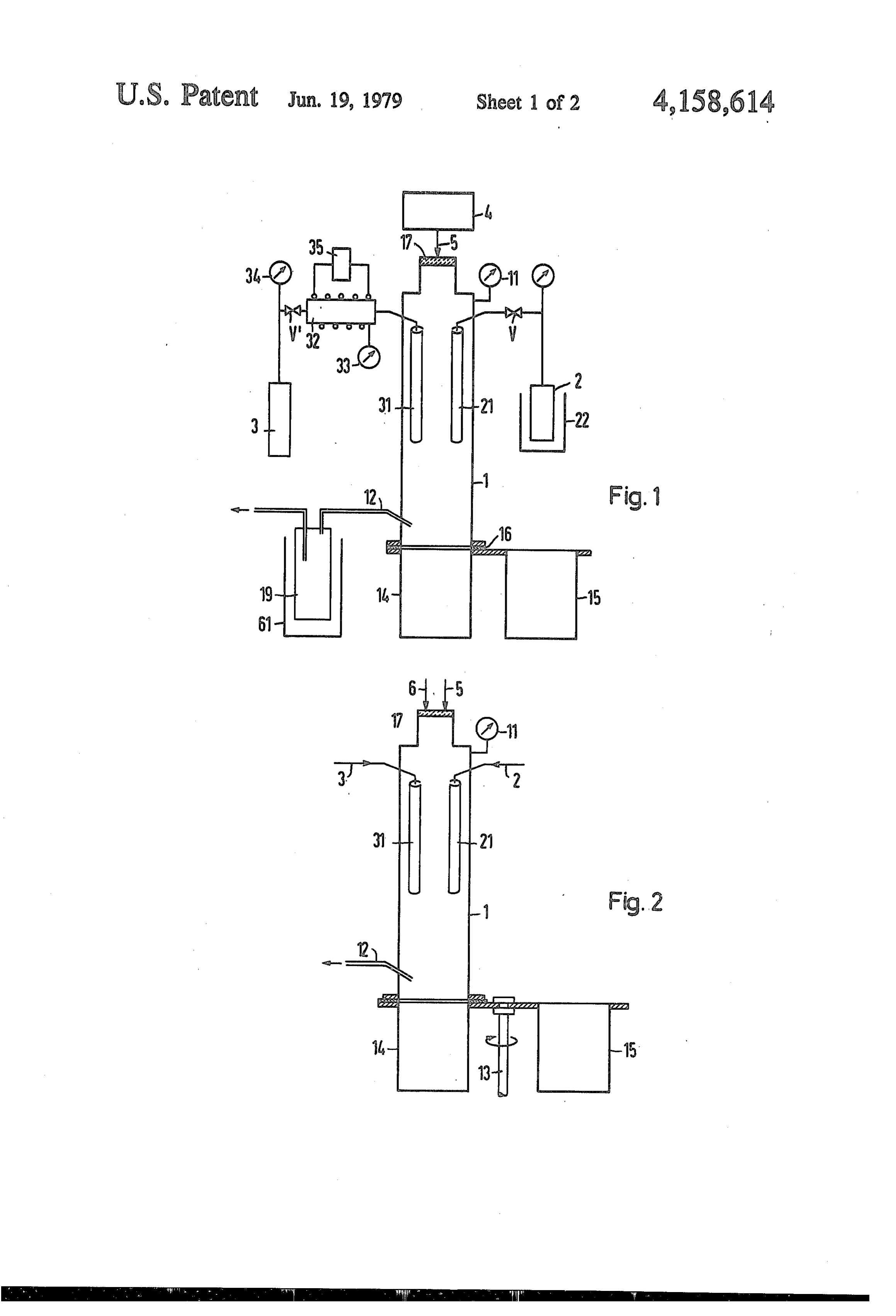
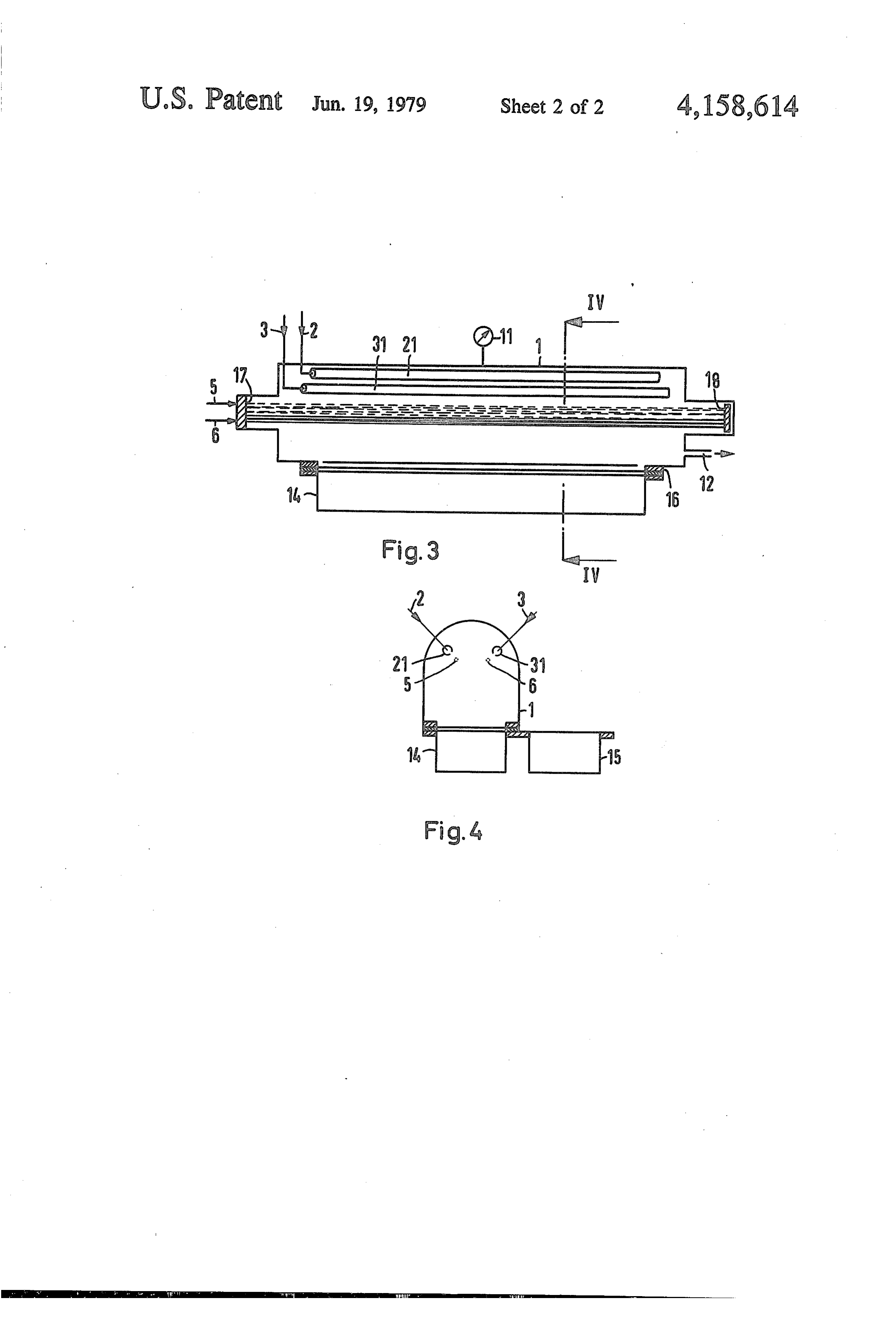
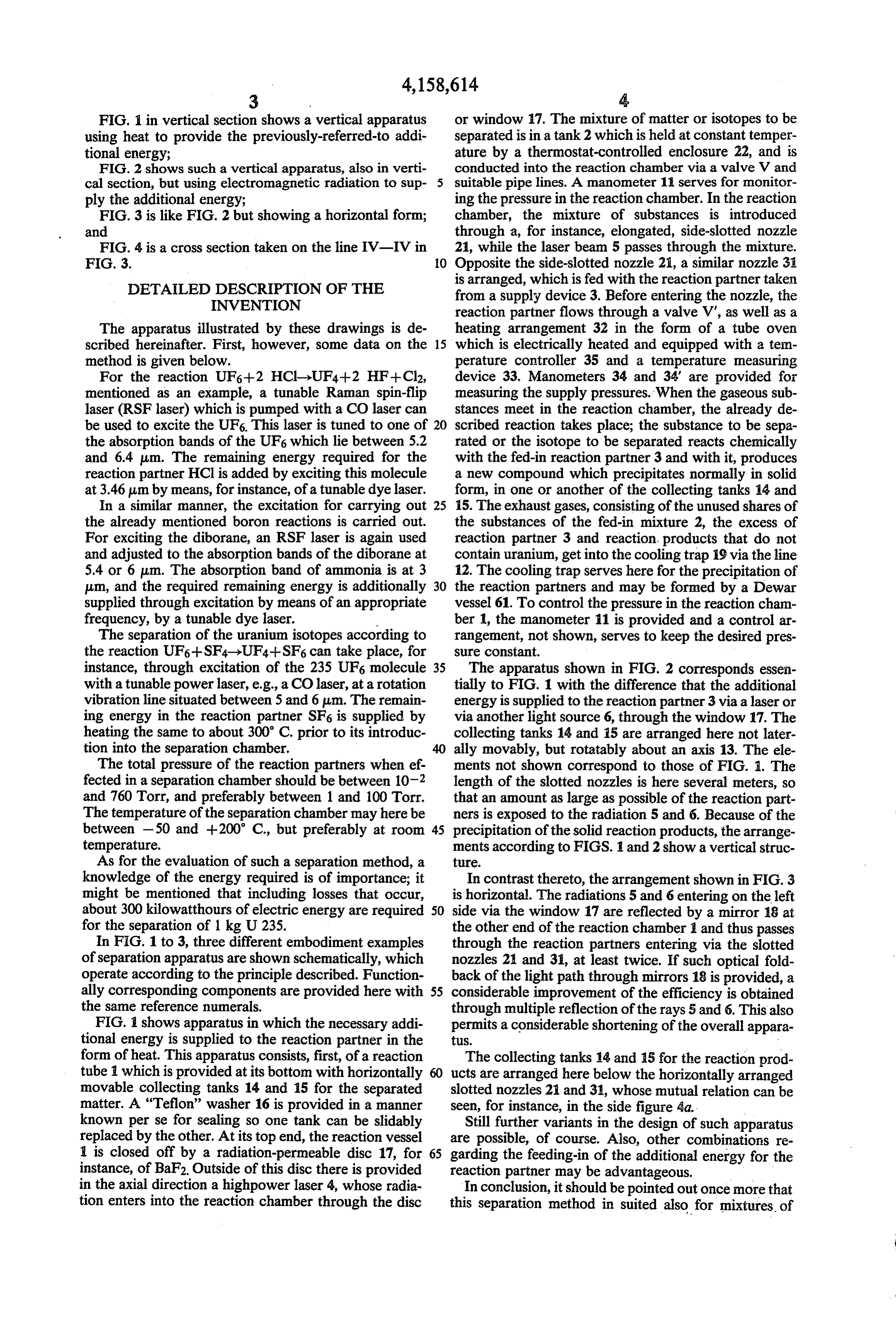
FIG. 1 in vertical section shows a vertical apparatus or window 17. The mixture of matter or isotopes to be using heat to provide the previously-referred-to addi separated is in a tank 2 which is held at constant temper tional energy; ature by a thermostat-controlled enclosure 22, and is FIG. 2 shows such a vertical apparatus, also in verti conducted into the reaction chamber via a valve V and cal section, but using electromagnetic radiation to sup suitable pipe lines. A manometer 11 serves for monitor ply the additional energy; ing the pressure in the reaction chamber. In the reaction FIG. 3 is like FIG. 2 but showing a horizontal form; chamber, the mixture of substances is introduced and through a, for instance, elongated, side-slotted nozzle FIG. 4 is a cross section taken on the line IV-IV in 21, while the laser beam 5 passes through the mixture. FIG. 3. 10 Opposite the side-slotted nozzle 21, a similar nozzle 31 DETAILED DESCRIPTION OF THE is arranged, which is fed with the reaction partner taken INVENTION from a supply device 3. Before entering the nozzle, the reaction partner flows through a valve V', as well as a
The apparatus illustrated by these drawings is de heating arrangement 32 in the form of a tube oven scribed hereinafter. First, however, some data on the 15 which is electrically heated and equipped with a ten method is given below. perature controller 35 and a temperature measuring For the reaction UF6+2 HCl-UF4--2 HF--Cl2, device 33. Manometers 34 and 34 are provided for mentioned as an example, a tunable Raman spin-flip measuring the supply pressures. When the gaseous sub laser (RSF laser) which is pumped with a CO laser can stances meet in the reaction chamber, the already de be used to excite the UF6. This laser is tuned to one of 20 scribed reaction takes place; the substance to be sepa the absorption bands of the UF6 which lie between 5.2 rated or the isotope to be separated reacts chemically and 6.4 um. The remaining energy required for the with the fed-in reaction partner 3 and with it, produces reaction partner HCl is added by exciting this molecule a new compound which precipitates normally in solid at 3.46 um by means, for instance, of a tunable dye laser. form, in one or another of the collecting tanks 14 and In a similar manner, the excitation for carrying out 25 15. The exhaust gases, consisting of the unused shares of the already mentioned boron reactions is carried out. the substances of the fed-in mixture 2, the excess of For exciting the diborane, an RSF laser is again used reaction partner 3 and reaction, products that do not and adjusted to the absorption bands of the diborane at contain uranium, get into the cooling trap 19 via the line 5.4 or 6 p.m. The absorption band of ammonia is at 3 12. The cooling trap serves here for the precipitation of um, and the required remaining energy is additionally 30 the reaction partners and may be formed by a Dewar supplied through excitation by means of an appropriate vessel 61. To control the pressure in the reaction cham frequency, by a tunable dye laser. - ber 1, the manometer 11 is provided and a control ar The separation of the uranium isotopes according to rangement, not shown, serves to keep the desired pres the reaction UF6--SF4->UF4--SF6 can take place, for Sure Constant.
instance, through excitation of the 235 UF6 molecule 35 The apparatus shown in FIG. 2 corresponds essen with a tunable power laser, e.g., a CO laser, at a rotation tially to FIG. 1 with the difference that the additional vibration line situated between 5 and 6 pum. The remain energy is supplied to the reaction partner 3 via a laser or ing energy in the reaction partner SF6 is supplied by via another light source 6, through the window 17. The heating the same to about 300 C. prior to its introduc collecting tanks 14 and 15 are arranged here not later tion into the separation chamber. ally movably, but rotatably about an axis 13. The ele The total pressure of the reaction partners when ef ments not shown correspond to those of FIG. I. The fected in a separation chamber should be between 10-2 length of the slotted nozzles is here several meters, so and 760 Torr, and preferably between 1 and 100 Torr. that an amount as large as possible of the reaction part The temperature of the separation chamber may here be ners is exposed to the radiation 5 and 6. Because of the between -50 and --200 C., but preferably at room 45 precipitation of the solid reaction products, the arrange temperature. ments according to FIGS. 1 and 2 show a vertical struc As for the evaluation of such a separation method, a ture.
knowledge of the energy required is of importance; it In contrast thereto, the arrangement shown in FIG. 3 might be mentioned that including losses that occur, is horizontal. The radiations 5 and 6 entering on the left about 300 kilowatthours of electric energy are required 50 side via the window 17 are reflected by a mirror 18 at for the separation of 1 kg U235. the other end of the reaction chamber 1 and thus passes In FIG. 1 to 3, three different embodiment examples through the reaction partners entering via the slotted of separation apparatus are shown schematically, which nozzles 21 and 31, at least twice. If such optical fold operate according to the principle described. Function back of the light path through mirrors 18 is provided, a ally corresponding components are provided here with 55 considerable improvement of the efficiency is obtained the same reference numerals. through multiple reflection of the rays 5 and 6. This also FIG. 1 shows apparatus in which the necessary addi permits a considerable shortening of the overall appara tional energy is supplied to the reaction partner in the tus.
form of heat. This apparatus consists, first, of a reaction The collecting tanks 14 and 15 for the reaction prod tube which is provided at its bottom with horizontally ucts are arranged here below the horizontally arranged movable collecting tanks 14 and 15 for the separated slotted nozzles 21 and 31, whose mutual relation can be matter. A "Teflon' washer 16 is provided in a manner seen, for instance, in the side figure 4a. - known per se for sealing so one tank can be slidably Still further variants in the design of such apparatus replaced by the other. At its top end, the reaction vessel are possible, of course. Also, other combinations re 1 is closed off by a radiation-permeable disc 17, for 65 garding the feeding-in of the additional energy for the instance, of BaF2. Outside of this disc there is provided reaction partner may be advantageous. in the axial direction a highpower laser 4, whose radia In conclusion, it should be pointed out once more that tion enters into the reaction chamber through the disc this separation method in suited also for mixtures of
Page 6
normal substances, i.e. not only for mixtures of isotopes, and the reaction partner is NH3, said band of wave particularly if separation by purely chemical or physical lengths is from 5.4 to 6 um and a light beam having a means presents considerable difficulties. wave length of about 3 um is projected through the What is claimed is: mixture to molecularly excite said reaction partner and . 1. A method for chemically separating isotopes from provide it with said addition energy. a mixture of gaseous matter formed by mixed isotopes 5. The method of claim 1 in which said mixed iso and a chemical reaction partner, by a reaction directed by a light beam projected through the mixture with the topes are 235UF6 and 238UF6 and said reaction partner is selected from the class consisting of SF4, SiCl4, HCl light beam having a narrow band of wave lengths mo and SO2 and the mixture is contained in a separation lecularly exciting mainly the isotope to be separated and 10 thereby promoting its reaction with the reaction part chamber into which the laser beam is projected, the ner, wherein the improvement comprises supplying the beam having a wave length between 5.2 and 6.4 pum reaction partner with addition energy to a degree sub molecularly exciting the 235 UF6, the mixture being stantially reducing the energy of the light beam re formed in said chamber by separately introducing the quired to promote said reaction in the absence of the 15 mixed isotopes and reaction partner into the chamber addition of the energy to the reaction partner. with the reaction partner excited by addition energy at 2. The method of claim 1 in which electromagnetic least while in the chamber.
radiation is projected through said mixture to add the 6. The method of claim 5 in which the reaction part energy to the reaction partner. ner is heated to about 300 C. prior to said introducing, 3. The method of claim 2 in which the wave length of 20 to provide it with said addition energy. said radiation is substantially the same as the molecular 7. The method of claim 5 in which electromagnetic resonance frequency of the reaction partner. radiation is projected into said chamber to provide the 4. The method of claim 1 in which said mixed iso reaction partner with the addition energy. topes are 10B and 11B and said gaseous matter is (BH3)2, t is
Provenance
- Collection
- Cited prior art
- Original PDF
- patentimages.storage.googleapis.com →
- Filed
- 1977-04-14
- Pages
- 6
- Method
- pdftotext (the PDF's own text layer) + pdftoppm 300dpi page scans
- Source
- Google Patents bibliographic record
- Granted
- 1979-06-19
- Inventors
- Eberhard Schuster; Arno Kersting; Kraftwerk Union AG
- Transcribed from
- patentimages.storage.googleapis.com →