patent · US3354333
Gramme armature dynamoelectric machine
21 November 1967
Page 1
Drawing sheet — no readable text.
Page 2
United States Patent Office 3,354,333 Patented Nov. 2, 1967
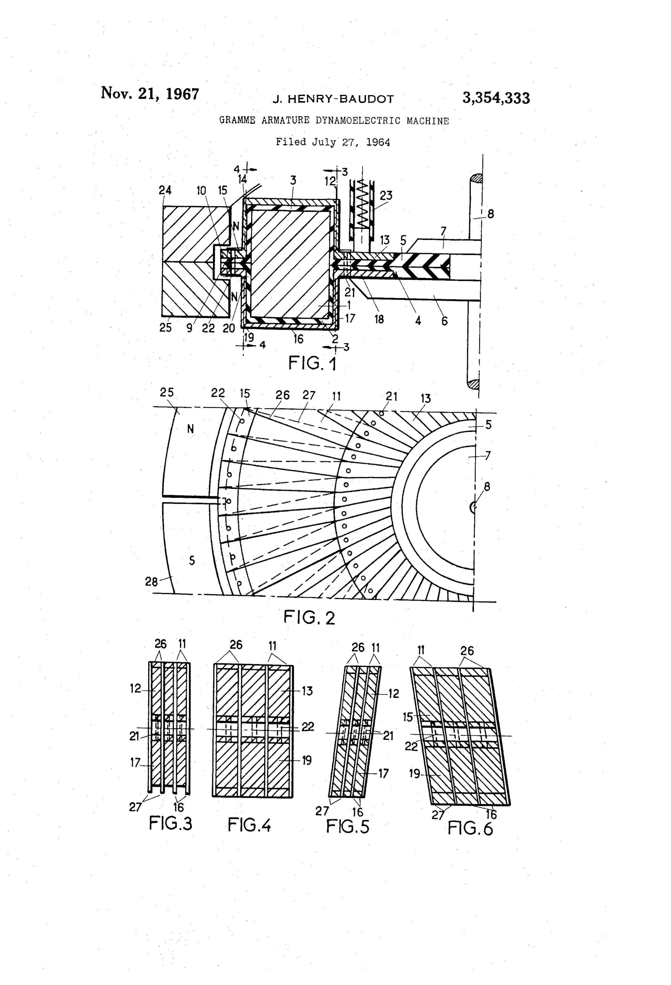
3,354,333 matter of choice and not imperative. Said magnetic core 1 GRAMMEARMATURE DYNAMOELECTRIC is sheathed by two half-shells 2 and 3 of insulating mate MACHINE rial and said half-shells have edges integral therewith, Jacques Henry-Baudot, Antony, France, assignor to inner edges 4 and 5, outer edges 9 and 10. Said edges de Printed Motors Inc., New York, N.Y. fine two insulating rings, an inner one and an outer one. Filed July 27, 1964, Ser. No. 385,221 The inner ring extends on a sufficient breadth to enable an Claims priority, application France, Aug. 21, 1963, easy and plain attachment of the armature to a shaft 8 by 945,327, Patent 1,373,824 means for instance of annular plates 6 and 7 pressing on 11 Ciaims. (Cil. 310-268) opposite sides of said edge ring and affixed to the shaft. The present invention concerns improvements in or O provided The outer ring is of limited radial extent since it is only relating to dynamoelectric machines, for example, of the here for through-connection purposes which will disc type with a Gramme armature, that is to say a toroid be herein later explained. Instead of providing two half carrying an uniformly wound winding, said winding being shellis it would have been possible as well to sheath the electrically connected in a closed loop and the current magnetic core with a moulded thermosettable or thermo thereof being conducted thereto by means of brushes, 15 proper polymerisable resin defining both the sheath on the core said armature being concentrically arranged with respect and the inner and outer rings, or in other words, to a ring of field creating magnetic poles. with the inner ring, since in such a case, the outer ring is The purpose of the invention is to improve the struc to no longer imperative. Such an alternative is too obvious tures of such machines, and chiefly, the structures of Such need any further showing or discussion. Gramme armatures. 20 The field induction magnets are shown at 25 and 28 In a conventional Gramme armature, an insulated wire on and FIG. 2, each of them may be in two parts as shown at is spirally wound on a toroidal carrier and this wire can 24 25 in the cross-section view of FIG. 1 for ease in only be of a constant cross-section; consequently, if one mounting them around the core and taking the outer makes the turns of the spiral contact each other on the radial edge in due consideration. Of course, when said outer portion of the carrier, such turns will overlap in 25 parts outer edge is omitted, the division of the magnets in two may be also omitted if desired.
the inner portion, or conversely, if one winds the turns When however one wishes to make the commutator so as to be in contact with each other on the inner side of the carrier, the turns will be spaced apart on the outer external to the core, the outer ring may be extended and side thereof. In both cases, the toroidal surface is ineffec the inductor field magnets may be distributed in two tively used and the electromagnetic eficiency cannot be an 30 rings facing each other from opposite sides of the arma optimum. Further a separate commutator must be pro ture. Such an alternative increases the overall diameter vided in the machine and consequently the efficiency of the machine, without any necessity thereto, so that said thereof is further decreased. alternative is only indicated as a possibility of embodi According to a feature of the invention, a Gramme 35 ment. The commutator comprises, in the example shown, con armature comprises the combination of a toroidal core ductor sections 13 on which bear, after the final mounting and a ring integral with said core and extending in a median plane thereof perpendicular to the axis of the of the machine, brushes such as 23. These sections are core, such a core and ring member including a magnetic parts of the conductive coatings of the member con material at least in the core part thereof and having an 40 stituted by the magnetic core , its sheath 2-3 and the insulating surface. Lamellar conductor means are intimate inner ring 4-5. They are end portions or extensions of half-turn conductors which are printed or otherwise ly adhered to said insulating surface and defined around formed adhering on the surfaces of the half-shells. The the core, a continuous and closed spiral covering nearly the entire surface and defining further on said ring a same applies to the short sections 18 on the other face commutator of as many sections as are turns in said closed of the inner insulating ring. Practically the blades are spiral. shown equal for symmetry reasons. According to another feature of the invention, such All conductors are substantially contiguous but have lamellar conductor means are printed-circuit conductor narrow gaps therebetween and, from one half-shell to means, obtained from any of the so-called “printed-circuit the other one, they are so oriented that a continuous techniques," i.e. any technique capable of repeatedly 50 closed spiral is obtained. This forms a winding of the true reproducing a conductive pattern on a surface and firmly Gramme armature type once the thru-connections as 21 adhering thereto. and 22 are made for example, by hole metallization of According to another feature of the invention, said holes provided at the near edge of the half-shells. ring extends towards the inner side of the core and also Consequently, the commutator and the winding are si acts as a carrier means for mounting the armature on a multaneously obtained with a nearly total coverage of the shaft. insulating surfaces. In order to ease the commutation, the A machine according to the invention comprises such commutator sections 13 are slanted with respect to the a Gramme armature associated with magnets placed on radial direction. The winding proper is made from parts either side of the core and a pair of brushes bearing on 2 and 14 of the condctive coating of the half-shell 3 the commutator sections. and the parts 17 and 19 of the conductive coating of the
These and further features will be described in detail 2, plus the link parts 14, half-shell 3, and 6, with reference to the accompanying drawings, wherein: half-shell 2, between the active portions of the turns, and FIG. 1 is a partial elevation view, in cross-section and the connections 22 and 21. Connections 22 are made be FIG. 2 is a partial top view, of a first example of embodi tween the conductor coatings 15 and 20 of the half-shells ment of a machine according to the invention; on their outer edges.
FIG. 3 is a section on the lines 3-3 of F.G. 1; In the example of FIGS. 1 to 4, the active portions FIG. 4 is a section on the lines 4-4 of FIG. 1; and 42-17 and 15-29 of the winding are shown orthogonal to FIGS. 5 and 6 are views similar to those of FIGS. 3 the upper and lower faces of the core, and consequently and 4, defining an alternative embodiment of the armature the inactive portions 1 and 16 are slanted in opposite of said machine. directions, for defining the pitch of the spiral. In the modi 70 fication shown in FIGS. 5 and 6, the active portions are
In said example of embodiment, the toroidal core d is slanted for defining the pitch of a turn of the spiral and made of square cross-section, this being of course a the inactive parts are substantially parallel to the axis
Page 3
3 a closed spiral winding comprising a series of conductive of rotation. Of course, the progressive pitch may be ob tained by the slants of both the active and inactive parts, members intimately bonded to the exterior of said which is now obvious from the two shown examples. insulating covering, said winding including commu When the core is not rectangular in cross-section, but has tator sections overlying and intimately bonded to said a cross-section of circular or ellipsoidal shape, the dis flat annulus portion of said rotor member, there be crimination between active and inactive parts becomes ing the same number of commutator sections as there indefinite and the pitch of the spiral may be better de are turns in said winding, said winding and com fined from a uniform slant on each one-half of the core, mutator sections substantially covering said rotor the upper and the lower ones for instance, or the external member;
and internal ones, as the case may be. In any case, as said, 10 a magnetic field structure at least partially surrounding the conductors are distributed over the quasi-totality of said rotor member;
the surface of the core, from which the efficiency of the and brushes contacting said commutator sections. armature is maximum. 2. Machine according to claim 1, wherein the conduc The "printing' of the winding and commutator may tive winding and commutator sections consist of printed circuit conductors on the said insulating covering.
have recourse as said to any printed-circuit technique.
Preferably, the half-shells have previously been “waffled” 3. A machine as defined by claim 2 wherein said com for defining thin relief lines such as 26 and 27 in the in mutator sections and the active portions of said closed sulation material. Copper is thereafter deposited on the spiral winding are thicker in cross section than the in active portions of said spiral winding.
insulating material up to a thickness more than the depth 4. Machine according to claim 1, wherein the core is of the depressions between the relief ridges, and there 20 made of a material which is both magnetic and conduc after the conductor ridges are abraded for the thus inlaid tive and said insulating surface obtained by an insulating conductors of the winding and commuator sections. By sheathing of said core with extended portions for making varying the depth of the depressions at the locations of the inactive parts of the winding and of the collector at least one inner ring perpendicular to the axis of rota blades in the direction of a greater depth for such parts, 25 tion5. ofMachine said core.
according to claim 4, wherein said sheath the conductor thickness is greater in such parts of the ing comprises two half-shells with edges in the mid plane circuit and consequently the resistance is lower, which increases the electromagnetic efficiency of the armature. of 6.symmetry of the magnetic core. Machine according to claim 1, wherein said core
For other printed circuit techniques, a similar result may be obtained by an overdeposition of copper on a first one, 30 and said annulus are made from a magnetic insulating material.
electrolytically for instance after the first deposition is 7. Machine according to claim 4, wherein at least on made.
Instead of providing a magnetic core sheathed by an in the inner side of the core, thru-connections are made for sulating material, one may have recourse to a magnetic closing the turns of the spiral winding coating on said in material which is also insulating so that the deposition of 35 sulating surface.
conductors thereon may be directly made on the surfaces the8.inner Machine according to claim 6, wherein at least on side of the core, thru-connections are made for of Such an insulating and magnetic member moulded as a closing the turns of the winding coating on the surface of core plus at least one commuator ring, with thru-connec said insulating member.
tions from one face to the other one of said member.
The inductor magnet ring may be further so shaped 40 mutator 9. Machine according to claim 7, wherein said com as to substantially enclose the core if required, the brushes sections extend from said conductor coatings, being nearer the center of the inner ring which is partly radially inwardly beyond the said thru-connection area. 10. Machine according to claim 1, wherein the conduc covered by the magnets. tive conductor coating of the commutator is constituted Any other variation from the above shown and de
Scribed arrangements does not escape the field of the in 45 of commutator sections slanted with respect to the radii of said rotor.
vention as defined by the appended claims. 11. Machine according to claim 5, wherein a short What is claimed is:
1. A rotary disc-type dynamoelectric machine of the ternal edgeouter is provided in the insulating sheath for the ex thru-connections between the conductors of the
Gramme armature type comprising in combination: 50 spiral winding. - a disc rotor member including a toroidal core and a References Cited fiat annulus integral with and extending perpen UNITED STATES PATENTS dicularly to the axis of rotation of said core, at least the core portion of said member being formed of 2,449,021 9/1948 Stahl -------------- 310-267
MILTON O. HIRSHFIELD, Primary Examiner, an insulating covering surrounding and adhered to said core; J. W. GBBS, Assistant Examiner,
Provenance
- Collection
- Cited prior art
- Original PDF
- patentimages.storage.googleapis.com →
- Filed
- 1964-07-27
- Pages
- 3
- Method
- pdftotext (the PDF's own text layer) + pdftoppm 300dpi page scans
- Source
- Google Patents bibliographic record
- Granted
- 1967-11-21
- Inventors
- Henry-Baudot Jacques; Printed Motors Inc
- Transcribed from
- patentimages.storage.googleapis.com →