patent · US4022173
Cross-flow vaporizer
10 May 1977
Page 1 — bibliographic record
United States Patent (19) (11) 4,022,173 Read (45) May 10, 1977 (54) CROSS-FLOW WAPORIZER 3,253,647 5/1966 DeShaies ....................... 123/122 E 3,855,980 12/1974 Weisz ............................. 123/122 E 76) Inventor: Frank E. Read, 702 Vardo Lane,
Lubbock, Tex. 79403 FOREIGN PATENTS OR APPLICATIONS (22) Filed: Aug. 11, 1975 1, 191520 10/1959 France ................... 123/122 E
Primary Examiner-Ronald H. Lazarus 52 U.S. Cl. ........................... 123/122 E; 123/133; Attorney, Agent, or Firm-Wendell Coffee
(51) Int. C.’........................................ F02M 31/00 (58) Field of Search ... 123/122 E, 122 A, 122 AB, A fuel vaporization chamber is used to vaporize fuel 123/133; 165/52; 261/145 and mix the fuel vapors with air. Fuel impinges against (56) References Cited an exhaust-heated wall and the vapors are mixed with the air in a cross-flow pattern. Unvaporized fuel drains
UNITED STATES PATENTS from the bottom of the vaporizer to a reservoir. l,603,660 l (0/1926 Cassella ............................. 123/133 l,763,450 6/1930 Deventer ....................... 123/122 A 17 Claims, 5 Drawing Figures
Page 2
Drawing sheet — no readable text.
Page 3
Drawing sheet — no readable text.
Page 4
Drawing sheet — no readable text.
Page 5
The specific nature of the invention, as well as other
CROSS-FLOW WAPORIZER objects, uses, and advantages thereof, will clearly ap pear from the following description and from the ac
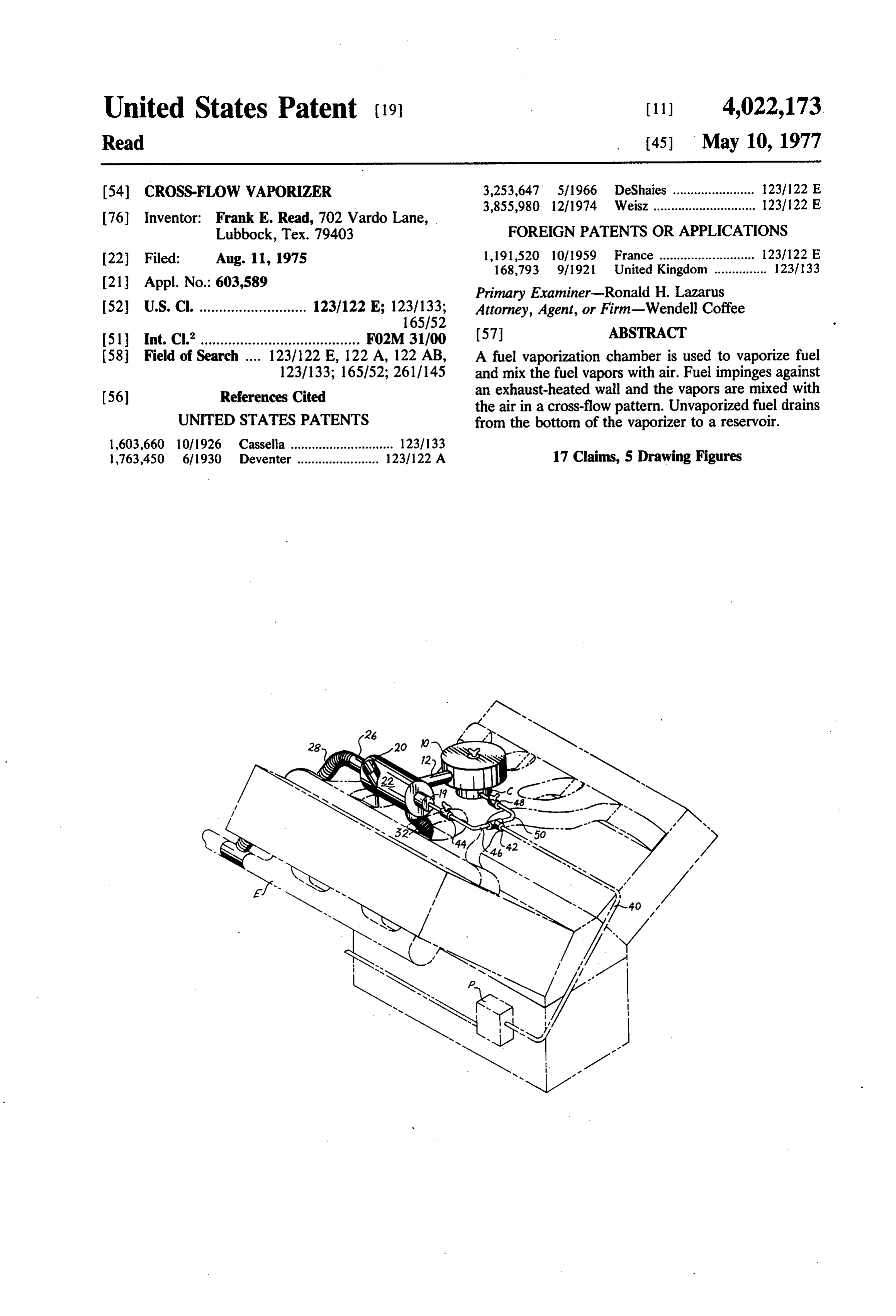
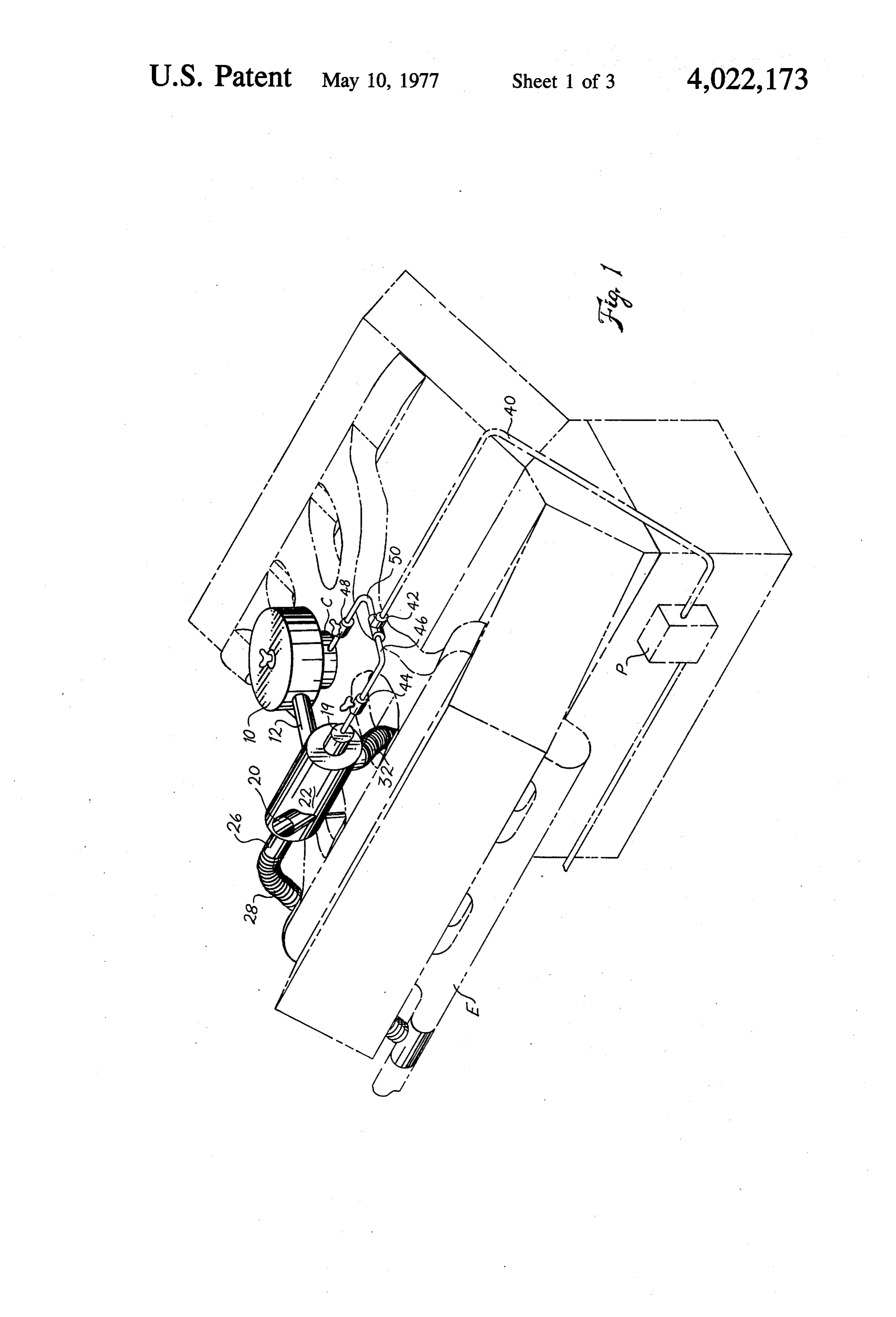
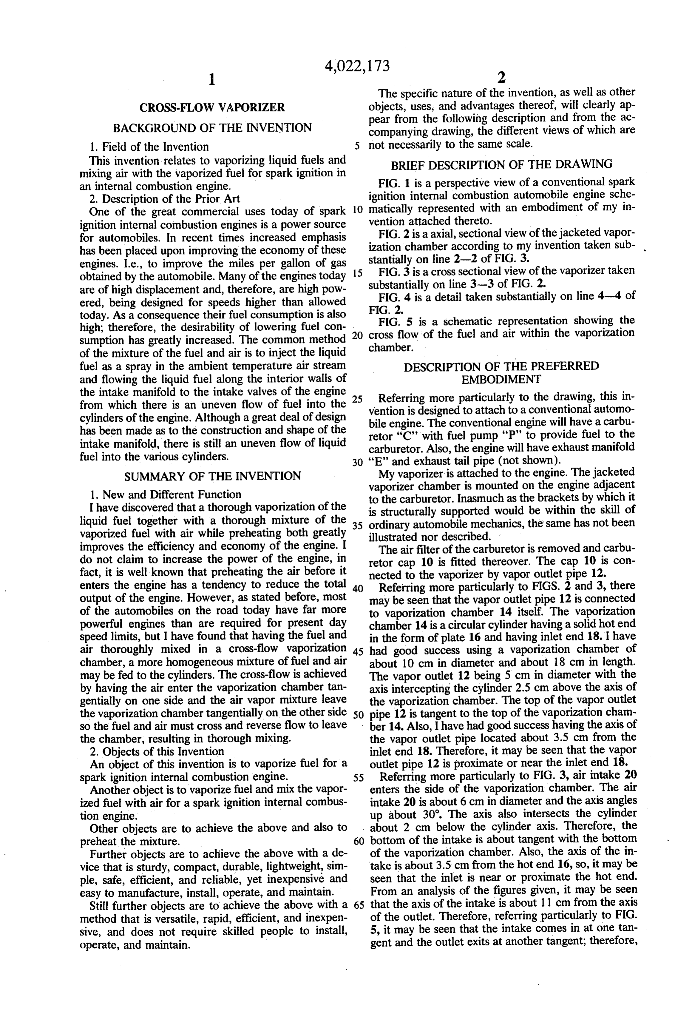
BACKGROUND OF THE INVENTION companying drawing, the different views of which are l. Field of the Invention 5 not necessarily to the same scale. This invention relates to vaporizing liquid fuels and BRIEF DESCRIPTION OF THE DRAWING mixing air with the vaporized fuel for spark ignition in FIG. 1 is a perspective view of a conventional spark an internal combustion engine. ignition internal combustion automobile engine sche 2. Description of the Prior Art
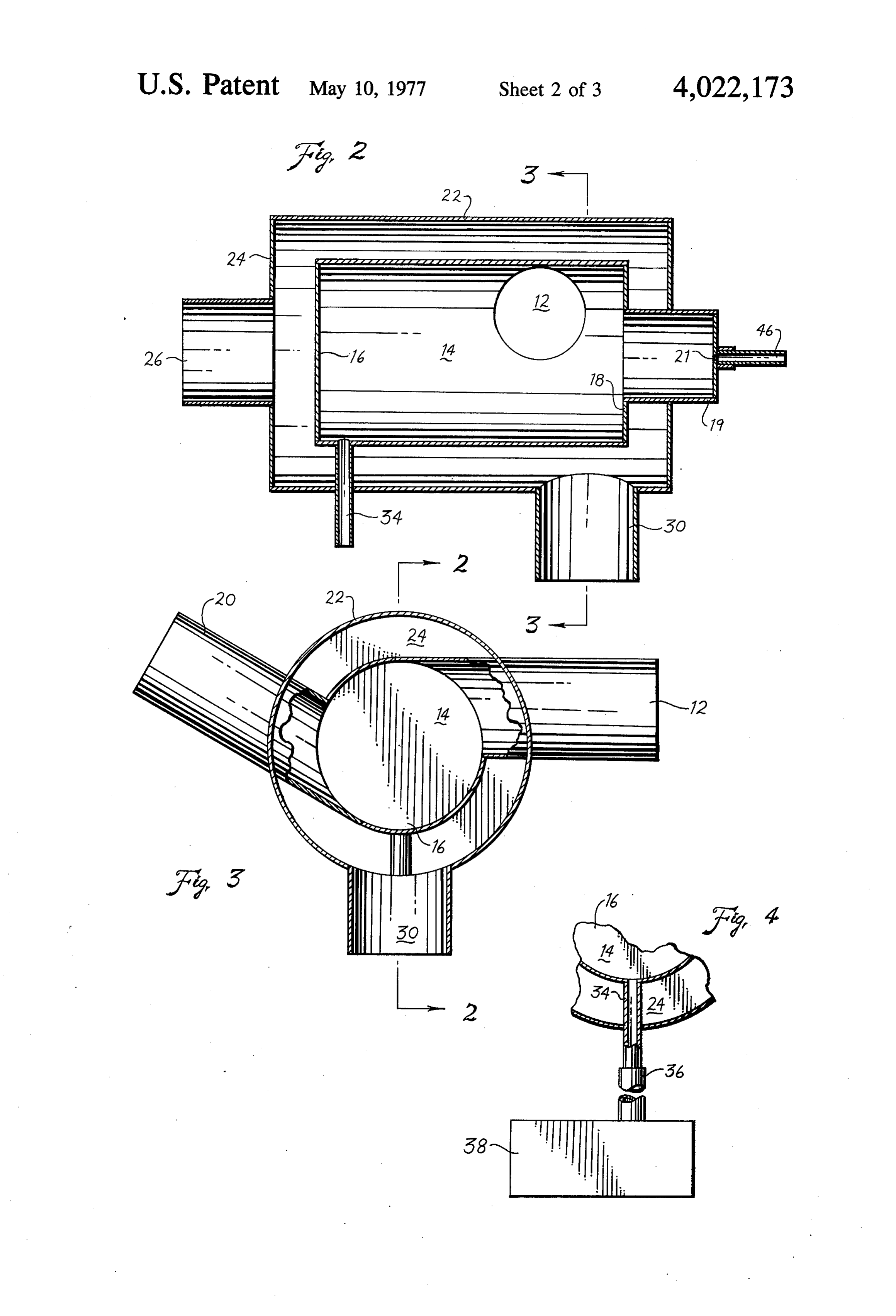
One of the great commercial uses today of spark 10 maticallyvention represented with an embodiment of my in attached thereto.
ignition internal combustion engines is a power source FIG. 2 is a axial, sectional view of the jacketed vapor for automobiles. In recent times increased emphasis ization chamber according to my invention taken sub has been placed upon improving the economy of these stantially on line 2-2 of FIG.
engines. I.e., to improve the miles per gallon of gas 15 FIG. 3 is a cross sectional view3.of the vaporizer taken obtained by the automobile. Many of the engines today substantially on line 3-3 of FIG. 2. are of high displacement and, therefore, are high pow FIG. 4 is a detail taken substantially on line 4-4 of ered, being designed for speeds higher than allowed FIG. 2.
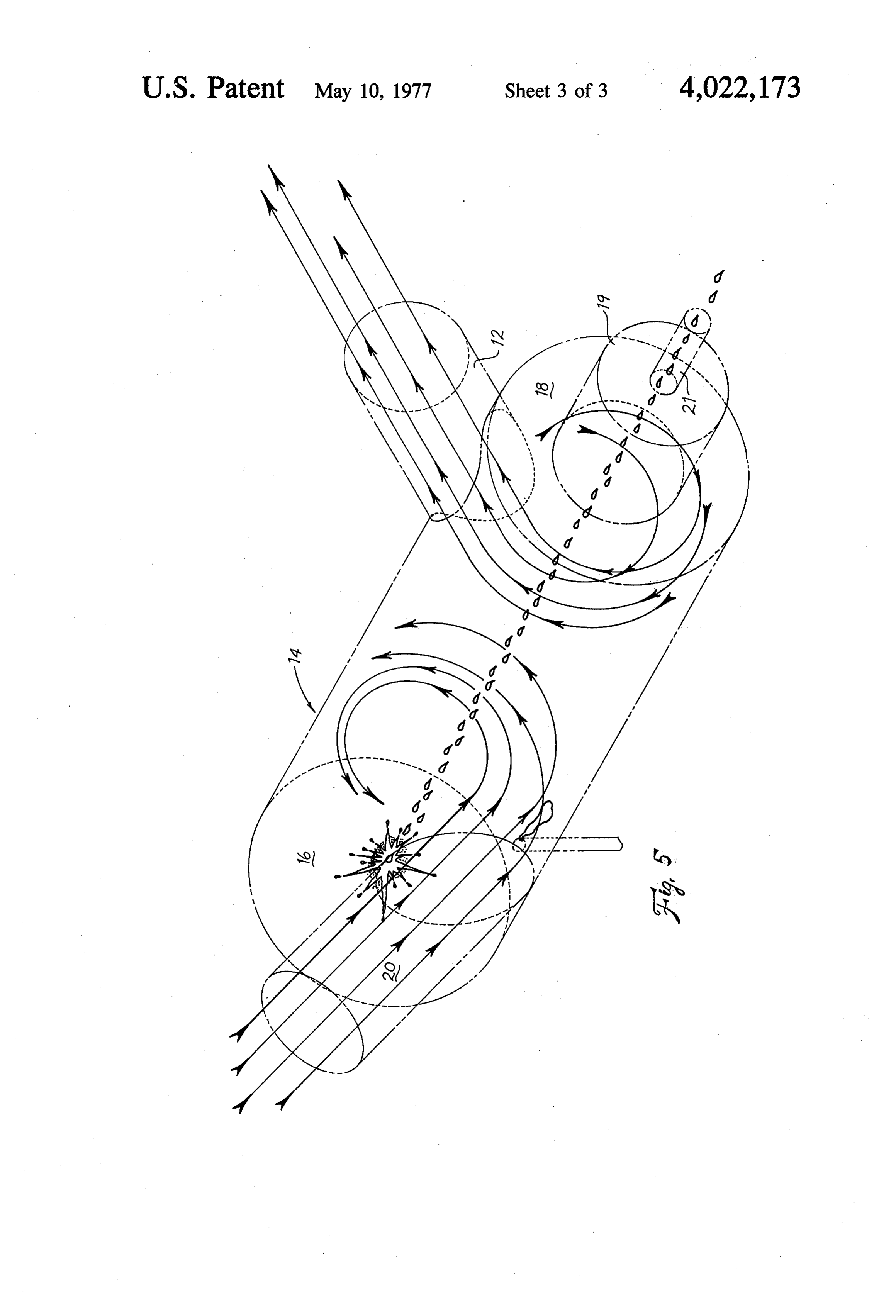
today. As a consequence their fuel consumption is also FIG. 5 is a schematic representation showing the high; therefore, the desirability of lowering fuel con 20 cross flow of the fuel and air within the vaporization Sumption has greatly increased. The common method chamber.
of the mixture of the fuel and air is to inject the liquid fuel as a spray in the ambient temperature air stream DESCRIPTION OF THE PREFERRED and flowing the liquid fuel along the interior walls of EMBODIMENT the intake manifold to the intake valves of the engine 25 Referring more particularly to the drawing, this in from which there is an uneven flow of fuel into the vention is designed to attach to a conventional automo cylinders of the engine. Although a great deal of design bile engine. The conventional engine will have a carbu has been made as to the construction and shape of the retor “C” with fuel pump “P” to provide fuel to the intake manifold, there is still an uneven flow of liquid carburetor. Also, the engine will have exhaust manifold fuel into the various cylinders. 30 "E' and exhaust tail pipe (not shown). SUMMARY OF THE INVENTION My vaporizer is attached to the engine. The jacketed 1. New and Different Function vaporizer chamber is mounted on the engine adjacent to the carburetor. Inasmuch as the brackets by which it
I have discovered that a thorough vaporization of the is structurally supported would be within the skill of liquid fuel together with a thorough mixture of the 35 ordinary automobile mechanics, the same has not been vaporized fuel with air while preheating both greatly illustrated nor described.
improves the efficiency and economy of the engine. I The air filter of the carburetor is removed and carbu do not claim to increase the power of the engine, in retor cap 10 is fitted thereover. The cap 10 is con fact, it is well known that preheating the air before it nected to the vaporizer by vapor outlet pipe 12. enters the engine has a tendency to reduce the total 40 Referring more particularly to FIGS. 2 and 3, there output of the engine. However, as stated before, most may be seen that the vapor outlet pipe 12 is connected of the automobiles on the road today have far more to vaporization chamber 14 itself. The vaporization powerful engines than are required for present day chamber 14 is a circular cylinder having a solid hot end speed limits, but I have found that having the fuel and in the form of plate 16 and having inlet end 18. I have air thoroughly mixed in a cross-flow vaporization 45 had good success using a vaporization chamber of chamber, a more homogeneous mixture of fuel and air about 10 cm in diameter and about 18 cm in length. may be fed to the cylinders. The cross-flow is achieved The vapor outlet 12 being 5 cm in diameter with the by having the air enter the vaporization chamber tan axis intercepting the cylinder 2.5 cm above the axis of gentially on one side and the air vapor mixture leave the vaporization chamber. The top of the vapor outlet the vaporization chamber tangentially on the other side 50 pipe 12 is tangent to the top of the vaporization cham so the fuel and air must cross and reverse flow to leave ber 14. Also, I have had good success having the axis of the chamber, resulting in thorough mixing. the vapor outlet pipe located about 3.5 cm from the 2. Objects of this Invention inlet end 18. Therefore, it may be seen that the vapor An object of this invention is to vaporize fuel for a outlet pipe 12 is proximate or near the inlet end 18. spark ignition internal combustion engine. 55 Referring more particularly to FIG. 3, air intake 20 Another object is to vaporize fuel and mix the vapor enters the side of the vaporization chamber. The air ized fuel with air for a spark ignition internal combus intake 20 is about 6 cm in diameter and the axis angles tion engine. up about 30°. The axis also intersects the cylinder Other objects are to achieve the above and also to about 2 cm below the cylinder axis. Therefore, the preheat the mixture. 60 bottom of the intake is about tangent with the bottom Further objects are to achieve the above with a de of the vaporization chamber. Also, the axis of the in vice that is sturdy, compact, durable, lightweight, sim take is about 3.5 cm from the hot end 16, so, it may be ple, safe, efficient, and reliable, yet inexpensive and seen that the inlet is near or proximate the hot end. easy to manufacture, install, operate, and maintain. From an analysis of the figures given, it may be seen Still further objects are to achieve the above with a 65 that the axis of the intake is about 11 cm from the axis method that is versatile, rapid, efficient, and inexpen of the outlet. Therefore, referring particularly to FIG. sive, and does not require skilled people to install, 5, it may be seen that the intake comes in at one tan operate, and maintain. gent and the outlet exits at another tangent; therefore,
Page 6
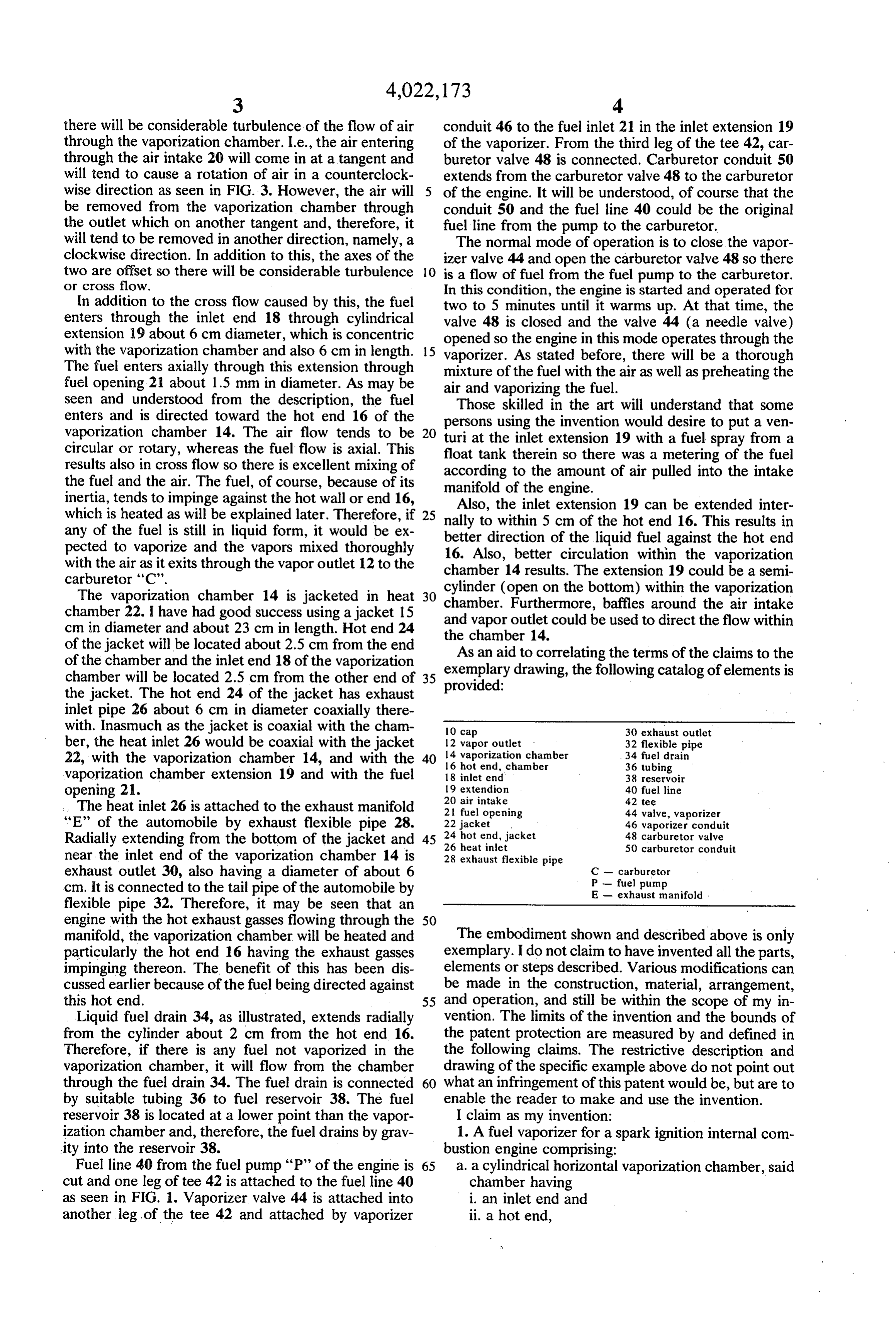
there will be considerable turbulence of the flow of air conduit 46 to the fuel inlet 21 in the inlet extension 19 through the vaporization chamber. I.e., the air entering of the vaporizer. From the third leg of the tee 42, car through the air intake 20 will come in at a tangent and buretor valve 48 is connected. Carburetor conduit 50 will tend to cause a rotation of air in a counterclock extends from the carburetor valve 48 to the carburetor wise direction as seen in FIG. 3. However, the air will of the engine. It will be understood, of course that the be removed from the vaporization chamber through conduit 50 and the fuel line 40 could be the original the outlet which on another tangent and, therefore, it fuel line from the pump to the carburetor. will tend to be removed in another direction, namely, a The normal mode of operation is to close the vapor clockwise direction. In addition to this, the axes of the izer valve 44 and open the carburetor valve 48 so there two are offset so there will be considerable turbulence O is a flow of fuel from the fuel pump to the carburetor. or cross flow. In this condition, the engine is started and operated for In addition to the cross flow caused by this, the fuel two to 5 minutes until it warms up. At that time, the enters through the inlet end 18 through cylindrical valve 48 is closed and the valve 44 (a needle valve) extension 19 about 6 cm diameter, which is concentric opened so the engine in this mode operates through the with the vaporization chamber and also 6 cm in length. 15 vaporizer. As stated before, there will be a thorough The fuel enters axially through this extension through mixture of the fuel with the air as well as preheating the fuel opening 21 about 1.5 mm in diameter. As may be air and vaporizing the fuel.
seen and understood from the description, the fuel Those skilled in the art will understand that some enters and is directed toward the hot end 16 of the vaporization chamber 14. The air flow tends to be 20 persons turi at using the invention would desire to put a ven the inlet extension 19 with a fuel spray from a circular or rotary, whereas the fuel flow is axial. This float tank therein so there was a metering of the fuel results also in cross flow so there is excellent mixing of according to the amount of air pulled into the intake the fuel and the air. The fuel, of course, because of its manifold of the engine.
inertia, tends to impinge against the hot wall or end 16, Also, the inlet extension 19 can be extended inter which is heated as will be explained later. Therefore, if 25 nally to within 5 cm of the hot end 16. This results in any of the fuel is still in liquid form, it would be ex pected to vaporize and the vapors mixed thoroughly better direction of the liquid fuel against the hot end with the air as it exits through the vapor outlet 12 to the chamber 14better 16. Also, circulation within the vaporization results. The extension 19 could be a semi carburetor 'C'.
The vaporization chamber 14 is jacketed in heat 30 chamber.cylinder (open on the bottom) within the vaporization chamber 22. I have had good success using a jacket 15 and vapor outlet Furthermore, baffles around the air intake cm in diameter and about 23 cm in length. Hot end 24 the chamber 14. could be used to direct the flow within of the jacket will be located about 2.5 cm from the end As an aid to correlating the terms of the claims to the of the chamber and the inlet end 18 of the vaporization exemplary drawing, the following catalog of elements is chamber will be located 2.5 cm from the other end of 35 the jacket. The hot end 24 of the jacket has exhaust provided:
inlet pipe 26 about 6 cm in diameter coaxially there with. Inasmuch as the jacket is coaxial with the cham 10 cap 30 exhaust outlet ber, the heat inlet 26 would be coaxial with the jacket 14 12 vapor outlet vaporization chamber 32 flexible pipe 34 fuel drain 22, with the vaporization chamber 14, and with the 40 16 hot end, chamber 36 tubing vaporization chamber extension 19 and with the fuel 18 inlet end 38 reservoir opening 21. 19 extendion 20 air intake 40 fuel line 42 tee
The heat inlet 26 is attached to the exhaust manifold 2 fuel opening 44 valve, vaporizer “E” of the automobile by exhaust flexible pipe 28. 24 22 jacket 46 vaporizer conduit Radially extending from the bottom of the jacket and 45 26 hot end, jacket heat inlet 48 carburetor valve 50 carburetor conduit near the inlet end of the vaporization chamber 14 is 28 exhaust flexible pipe exhaust outlet 30, also having a diameter of about 6 C - carburetor P - fuel pump cm. It is connected to the tail pipe of the automobile by E - exhaust manifold flexible pipe 32. Therefore, it may be seen that an engine with the hot exhaust gasses flowing through the 50 manifold, the vaporization chamber will be heated and The embodiment shown and described above is only particularly the hot end 16 having the exhaust gasses exemplary. I do not claim to have invented all the parts, impinging thereon. The benefit of this has been dis elements or steps described. Various modifications can cussed earlier because of the fuel being directed against be made in the construction, material, arrangement, this hot end. and operation, and still be within the scope of my in
Liquid fuel drain 34, as illustrated, extends radially vention. The limits of the invention and the bounds of from the cylinder about 2 cm from the hot end 16. the patent protection are measured by and defined in Therefore, if there is any fuel not vaporized in the the following claims. The restrictive description and vaporization chamber, it will flow from the chamber drawing of the specific example above do not point out through the fuel drain 34. The fuel drain is connected 60 what an infringement of this patent would be, but are to by suitable tubing 36 to fuel reservoir 38. The fuel enable the reader to make and use the invention. reservoir 38 is located at a lower point than the vapor I claim as my invention:
ization chamber and, therefore, the fuel drains by grav 1. A fuel vaporizer for a spark ignition internal com ity into the reservoir 38. bustion engine comprising:
Fuel line 40 from the fuel pump “P” of the engine is 65 a. a cylindrical horizontal vaporization chamber, said cut and one leg of tee 42 is attached to the fuel line 40 chamber having as seen in FIG. 1. Vaporizer valve 44 is attached into i. an inlet end and another leg of the tee 42 and attached by vaporizer ii. a hot end,
Page 7
b. a liquid fuel opening into the vaporization cham 10. The invention as defined in claim 9 with an addi ber axially aligned with the chamber at the: inlet tional limitation of end, - .. ‘. . . . . . . . . . . o. said liquid drain being proximate the hot end of the c. a cylindrical jacket around the vaporization cham 5 vaporization chamber. ', 11. The invention as defined in claim 10 with an ber, .. . .' -
d. said jacket having an exhaust heat inlet therein additional limitation of directed toward the axis of the hot end of the va p. said exhaust outlet extending radially from said porization chamber, . .. . . jacket near the inlet end of said vaporization cham e. said jacket having an exhaust outlet therefrom ber. . . ', . . . f a liquid drain from the vaporization chamber at a 10 additional 12. The invention as defined in claim 11 with an limitation of
g. a cylindrical vapor outlet pipe whose top extends q said jacket concentric with said vaporization tangentially from the top of the vaporization cham chamber.
ber 13. The invention as defined in claim 12 with an h. the axis of the outlet pipe being above the axis of 15 additional limitation r. said exhaust inletofconcentric with said vaporization the vaporization chamber, and chamber.
i. a cylindrical air intake pipe whose bottom extends 14. In a spark ignition internal combustion engine tangentially from the vaporization chamber. having 2. The invention as defined in claim 1 wherein j. said vaporizer is connected to said internal combus 20 a.b. aa carburetor, fuel pump to pump fuel to the carburetor, and tion engine, c. an exhaust manifold; k. said vapor outlet pipe connected to a carburetor d. the improved fuel vaporizer in combination with on the internal combustion engine in lieu of the air the above comprising: filter, e. a cylindrical, horizontal vaporization chamber m. the exhaust heat inlet connected to an exhaust 25 having outlet from said internal combustion engine, i. an inlet end and n. said exhaust outlet from the jacket connected to a ii. a hot end, tail pipe of the internal combustion engine, f. a liquid fuel opening into the vaporization chamber o. the liquid drain connected to a fuel reservoir, and 30 axially aligned with the chamber at the inlet end, p. the liquid fuel inlet connected by conduit to a fuel g. a conduit extending from the fuel pump to the fuel pump on the internal combustion engine. opening to provide fuel thereto, 3. The invention as defined in claim 2 with additional h. a cylindrical jacket around the vaporization cham limitations of ber coaxial therewith, q. a tee in the conduit from the fuel pump to the fuel 35 j. an exhaust heat inlet in said jacket, inlet of the vaporization chamber, k. said exhaust heat inlet coaxial with said jacket and r. a valve in the conduit from the tee to the vaporiza said vaporization chamber, and tion chamber, and m. proximate the hot end of the vaporization cham s, a conduit from the tee to the carburetor, and ber, t, a valve in a conduit from the tee to the carburetor. 40 n. a flexible pipe connecting the exhaust manifold to 4. The invention as defined in claim 1 with an addi the exhaust heat inlet, tional limitation of o. an exhaust outlet in said jacket, j. said liquid drain being proximate the hot end of the p. said exhaust outlet from the jacket being radially vaporization chamber. therefrom and near the inlet end of the vaporiza 5. The invention as defined in claim 1 with an addi 45 tion chamber, tional limitation of q. a flexible pipe connected to the exhaust outlet, j. said exhaust outlet extending radially from said r. a liquid drain from the vaporization chamber near jacket near the inlet end of said vaporization cham the hot end thereof extending radially from a low ber. point of the vaporization chamber, 6. The invention as defined in claim 1 with an addi 50 s. a fuel reservoir, tional limitation of t. a tube connecting the fuel drain to the fuel reser j. said jacket concentric with said vaporization cham VOIr, ber. u. a cylindrical vapor outlet extending tangentially on 7. The invention as defined in claim 6 with an addi one side of the vaporization chamber, tional limitation of 55 v. said vapor outlet connected to a cap, k. said exhaust inlet concentric with said vaporization w. said cap attached to the carburetor of the engine chamber. in lieu of an air filter, 8. The invention as defined in claim 1 with an addi X. the axis of the vapor outlet above the axis of the tional limitation of vaporization chamber, and k. said cylindrical air intake pipe having its axis below 60 y. an air intake entering tangentially into the vapor the axis of the vaporization chamber. ization chamber on the other side thereof from the 9. The invention as defined in claim 8 with additional vapor outlet, limitations of Z. said air intake having an axis below the axis of the m. said air intake pipe closer to the hot end than the vaporization chamber, inlet end and on the opposite side from the vapor 65 aa. said air intake closer to the hot end of the vapor outlet, ization chamber than the inlet end, and n. said vapor outlet pipe being nearer the inlet end bb. said vapor outlet being closer to the inlet end of than the hot end. the vaporization chamber than the hot end.
Page 8
15. The invention as defined in claim 14 with addi c. introducing air having a tangential flow in a first tional limitations of direction near the hot end plate and cc. a tee in the conduit from the fuel pump, d. removing the mixed fuel vapors and air by a tan dd. a vaporizer valve in the conduit from the tee to gential outlet having a flow in a second direction the vaporizer, and 5 near the fuel inlet, whereby ee. a conduit from the tee to the carburetor with a e. there is a cross flow of the intake air and mixed carburetor valve therein. vapor as well as the air having a cross flow with 16. The method of vaporizing liquid fuel and mixing respect to the fuel.
the vaporized liquid fuel with air, comprising: 17. The invention as defined in claim 16 with an a. axially introducing the fuel into a cylindrical va- 10 additional limitation of porization chamber, f. draining unvaporized fuel from the bottom of the b. impinging the liquid fuel toward a hot end plate of vaporization chamber.
the cylindrical chamber, e ski ak xk
Provenance
- Collection
- Cited prior art
- Original PDF
- patentimages.storage.googleapis.com →
- Filed
- 1975-08-11
- Pages
- 8
- Method
- pdftotext (the PDF's own text layer) + pdftoppm 300dpi page scans
- Source
- Google Patents bibliographic record
- Granted
- 1977-05-10
- Inventors
- Frank E. Read
- Transcribed from
- patentimages.storage.googleapis.com →