patent · US4018279
In situ coal combustion heat recovery method
19 April 1977
Page 1 — bibliographic record
United States Patent 19 11, 4,018,279 Reynolds et al. 45 Apr. 19, 1977 54 INSITU COAL COMBUSTION HEAT Primary Examiner-Ernest R. Purser RECOVERY METHOD Attorney, Agent, or Firm-Head, Johnson & Chafin 76) Inventors: Merrill J. Reynolds, 611 1 E. Skelly
Drive, Tulsa, Okla. 74135; Ralph W. 57 ABSTRACT
Disney, 124 E. 4th St., Tulsa, Okla. A method for recovery of heat generated by the com
bustion of coal in situ within coal seams in the earth.
22 Filed: Nov. 12, 1975 Three embodiments are described: one, in which the (21) Appl. No.: 631,108 coal seam crops out and into which can be drilled and inserted a pipe, through the coal seam, to a central 52 U.S. Cl. ............................ 166/258; 48/DIG. 6; point, where it is joined with a vertical pipe drilled from 165/45; 166/272 the surface. Water is supplied to the pipe at the point of 51) Int. Cl.................... F28D 21/00; E2B 43/25 outcrop. Fires are started within the coal seam and 58) Field of Search .................. 48/DIG. 6; 165/45; supplied with air from the surface by means of drilled 166/261,269,256-258, 272; 29914; 175/12 boreholes. The heat of combustion converts the water (56) References Cited in the pipe to steam which travels up the vertical pipe and is used to drive a turbine generator system. A sec
UNITED STATES PATENTS ond embodiment is used where there is an overlying 2,497,868 2/1950 Dalin ................................. 66/256 aquafer above the coal seam. Fires are started by 2,969,226 1/1961 Huntington. ... 166/272 X means of air supplied through boreholes leading from 2,994,375 8/1961 Hurley ............................... 166/261 the surface into the coal seam. The heat of combustion 3,016,953 1/1962 Mary ....... ... 1661258 converts the water in the aquafer to steam, which then 3,072, 87 - 11963 Carr .................................. 166/258 is circulated out of the aquafer and up to the surface 3, 59,215 12/1964 Meldau et al...................... 166/258 where it drives a turbine generator system. A third 3,294,167 12/1966 Vogel .................. ... 1661258 embodiment uses the hot combustion gases to heat 3,323,590 6/1967 Gilchrist et al. . ... 1661258 3,349,846 10/1967 Trantham et al. ... 166/258 water to steam in pipes in a vertical borehole. 3,554,285 1/1971 Meldau ................... ... 1661258 3,599,714 8/1971 Messman et al. ....... ... 1661258 3,809,159 5/1974 Young et al. ...................... 661258 4 Claims, 6 Drawing Figures
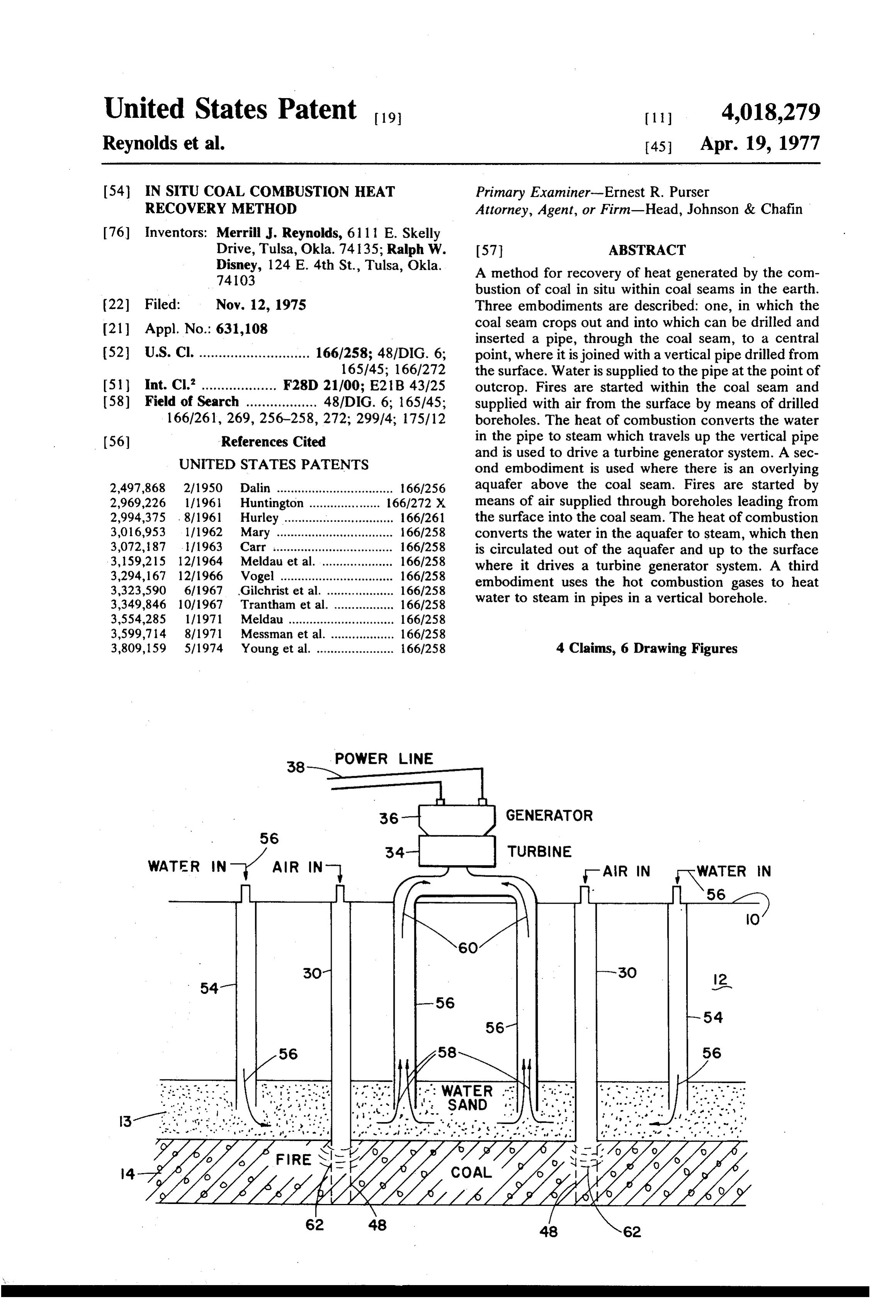
WATER IN-1 Air IN 34- TURBINE -AIR IN WATER N
Page 2
Drawing sheet — no readable text.
Page 3
Drawing sheet — no readable text.
Page 4
Drawing sheet — no readable text.
Page 5
holes can be supplied from the surface of the coal bed,
INSITU COAL COMBUSTION HEAT RECOVERY on both sides of the horizontal pipes, so that combus METHOD tion can be carried on along the position of the horizon tal pipes. The horizontal pipes are supplied with water
BACKGROUND OF THE INVENTION at the outcrop. The water will be heated and converted to steam, and can be carried to the surface through a 1. Field of the Invention vertical pipe drilled from the surface, and adapted to This invention lies in the field of energy recovery. intersect the horizontal pipe or pipes. A plurality of More particularly, it is concerned with the in situ com such horizontal pipes can be directed in different direc bustion in shallow thin beds of coal, at shallow depths O tions, from the outcrop to a central vertical pipe, or the below the surface of the earth. Still more particularly, use of several vertical pipes can be used. the invention lies in the field of the combustion of the Another object of this invention is to provide a means coal by supplying air to the coal seam from the surface for utilizing the heat resulting from the combustion of and utilizing the heat generated by the coal combustion coal in situ in normally unminable coal veins, at a shal to generate steam which is utilized at the surface of the 15 low depth below the surface. This is particularly useful ground, utilizing the earth (coal and surrounding where there is a water bearing formation directly rocks) as the furnace in the same manner as if it were above, and in contact with, the coal seam, or where geothermal. there is a hydrocarbon bearing formation, where the oil In one application, this invention lies in the field of is of such high viscosity that it cannot be produced by outcropping seams of coal where horizontal conduits 20 ordinary means. Here, by causing an artificial combus can be drilled and placed within the coal seam to a tion, in situ, in the coal seam, the heat of combustion specific point, where they join a vertical pipe. Water passes upward into the overlying aquafer and the water supplied to the horizontal pipes at the outcrop is heated is heated and converted to steam, and is produced by within the pipes by the combustion of the coal around one or more vertical pipes drilled into the water sand the pipes, and steam thus formed is carried up the 25 from the surface. The natural flow of water in the vertical pipe to be used to drive a turbine generator aquafer can replenish the water lost by steam, or addi system. tional vertical boreholes can be provided for the intro A still further application lies in the field of utilizing duction of water under pressure into the aquafer. coal seams thin or thick, shallow or deep overlain by If the overlying bed above the coal seam carries a water sands or by hydrocarbon bearing formations 30 very viscous oil, then the heat of combustion, after due whereby fires are started within the coal seam, and the course of time for the transmission of the heat verti heat of combustion is then communicated to the over cally into the overlying formation, will cause the viscos lying aquafer or oil formation. If the overlying bed is an ity to be reduced to a point where it can be produced aquafer then steam will be formed which can be carried by gas drive or water drive. If water is used then there to the surface to drive an electric generator system. If 35 will be a combination of water and steam drive to force the overlying bed contains viscous oil, then the heat the oil, now of reduced viscosity, out through appropri will cause the oil to be reduced in viscosity sufficient so ate producing wells.
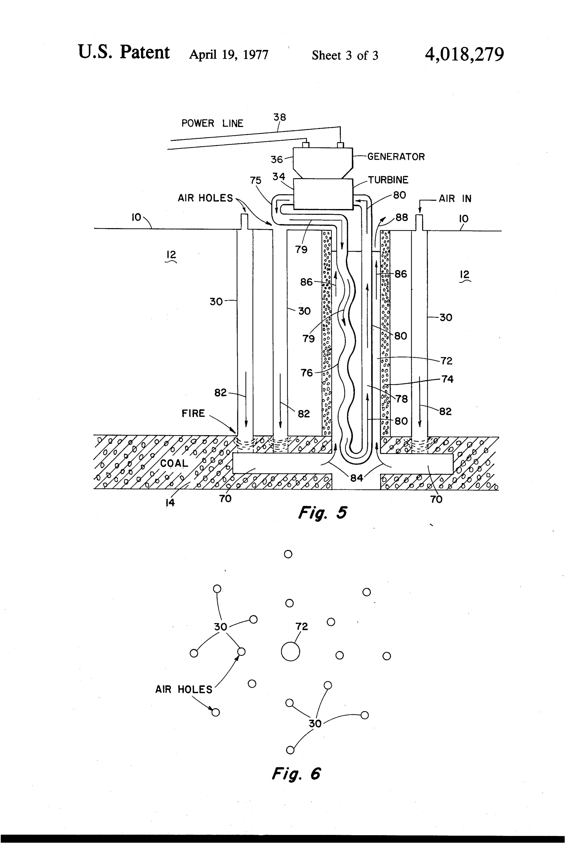
that it can be driven by a steam drive, or by pumping In a third embodiment, the hot gaseous products of water into the seam, which in view of the fire in the coal combustion are carried to a vertical borehole in which seam will turn to steam, which will drive the oil to the 40 is installed a coiled pipe, through which water is passed surface to be collected. from the surface. The water is heated by heat transfer Still a further application involves the burning of coal to the pipe from the hot gases as they flow up the bore in situ and carrying the hot gaseous products of com hole. The water is converted to steam which flows to a bustion up a vertical borehole past a coiled pipe carry turbine, etc.
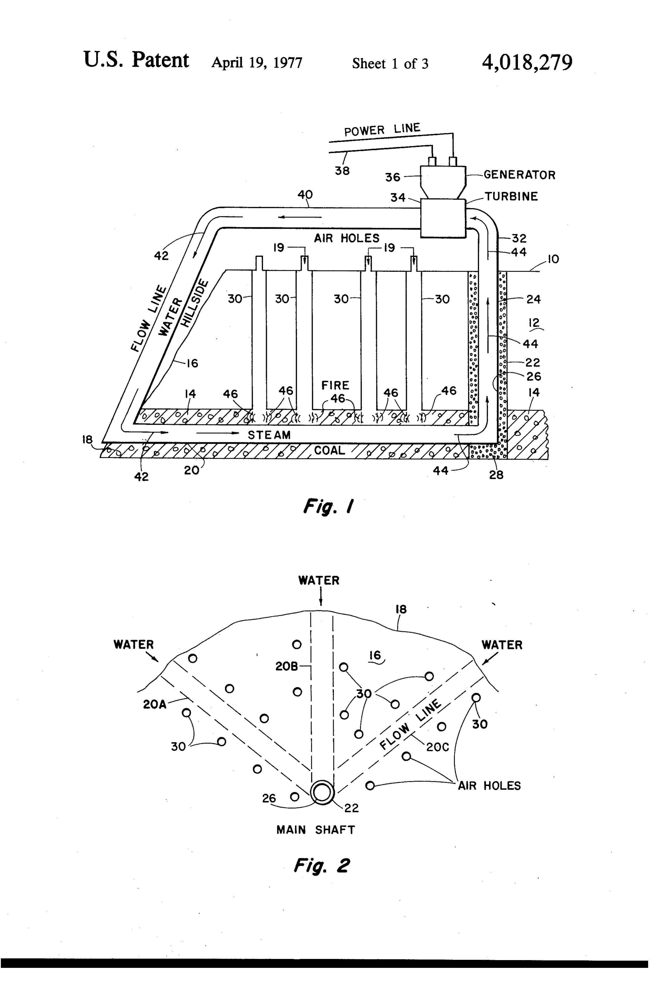
ing water. Heat is transferred to the water by convec 45 BRIEF DESCRIPTION OF THE DRAWINGS tion, forming steam which is carried to a turbine, etc.
2. Description of the Prior Art These and other objects and advantages of this inven Subsurface combustion of coal has been carried on in tion and a better understanding of the principles and nature, by fires of unknown origin which were started details of the invention will be evident from the follow many years ago and are burning continuously to the 50 ing description taken in conjunction with the appended present date. Also oil companies, coal companies and drawings, in which:
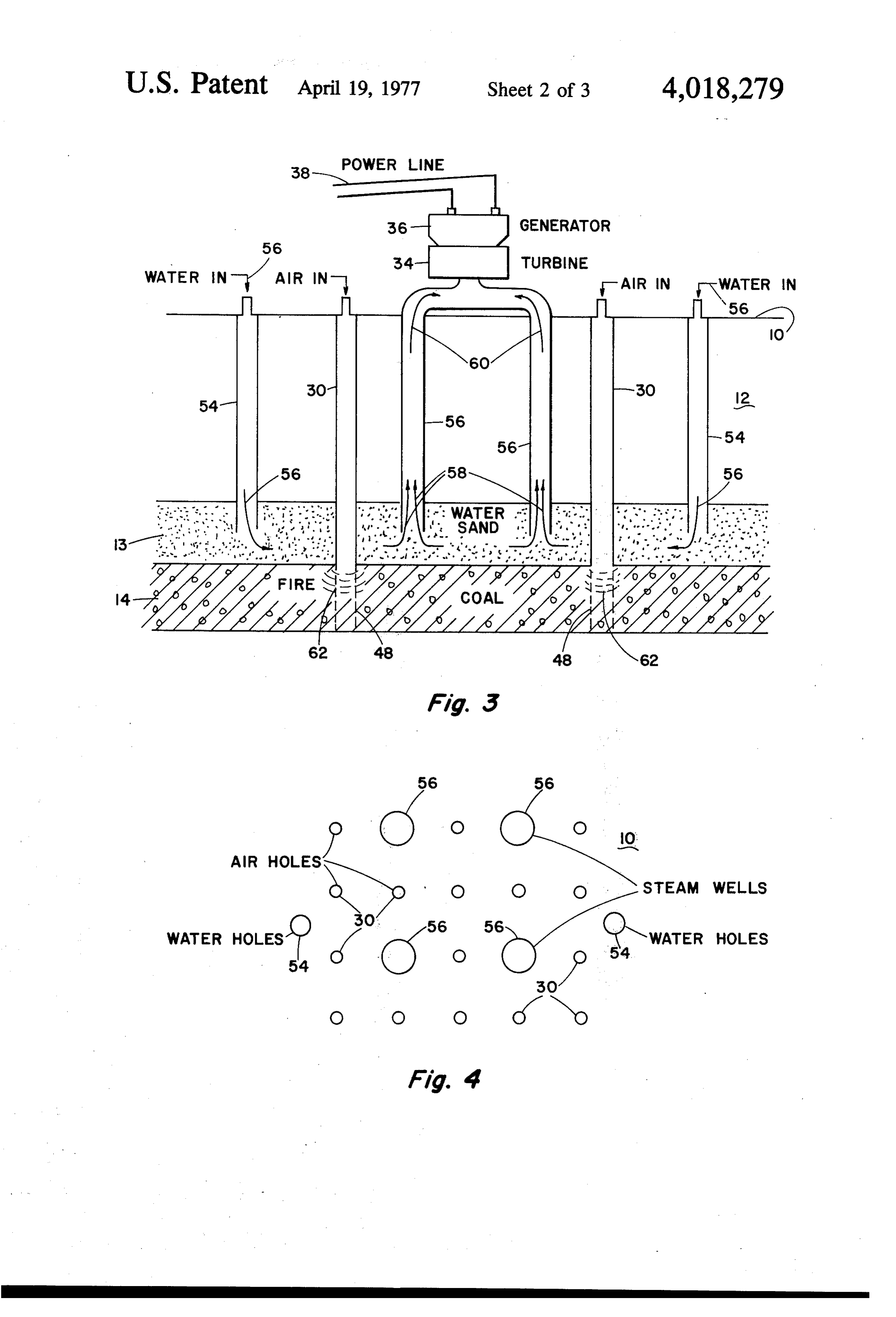
government research laboratories have investigated FIGS. 1 and 2 illustrate in vertical cross-section and many ways of underground combustion of coal, so as to plan views, one embodiment of this invention. utilize the products of combustion directly, as a coal FIGS. 3 and 4 illustrate two views, in vertical section gasification system. However, none of these methods 55 and in plan view, of a second embodiment of this inven have become practical as of the present date because of tion.
one or more basic difficulties. FIGS. 5 and 6 illustrate two views of a third embodi ent,
SUMMARY OF THE INVENTION
DESCRIPTION OF THE PREFERRED
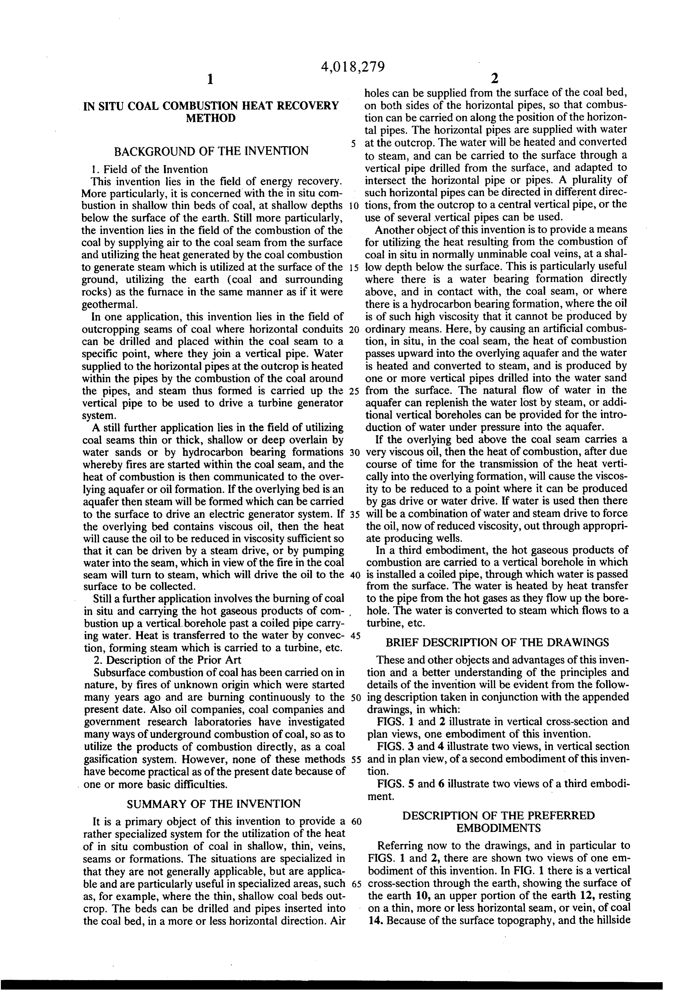
It is a primary object of this invention to provide a 60 EMBODIMENTS rather specialized system for the utilization of the heat of in situ combustion of coal in shallow, thin, veins, Referring now to the drawings, and in particular to seams or formations. The situations are specialized in FIGS. 1 and 2, there are shown two views of one em that they are not generally applicable, but are applica bodiment of this invention. In FIG. 1 there is a vertical ble and are particularly useful in specialized areas, such 65 cross-section through the earth, showing the surface of as, for example, where the thin, shallow coal beds out the earth 10, an upper portion of the earth 12, resting crop. The beds can be drilled and pipes inserted into on a thin, more or less horizontal seam, or vein, of coal the coal bed, in a more or less horizontal direction. Air 14. Because of the surface topography, and the hillside
Page 6
16, there will be an outcropping at 18 of the coal seam a boiler so as to utilize the further heat value of the 14. Because of the availability of the outcrop 18, one or products of combustion.
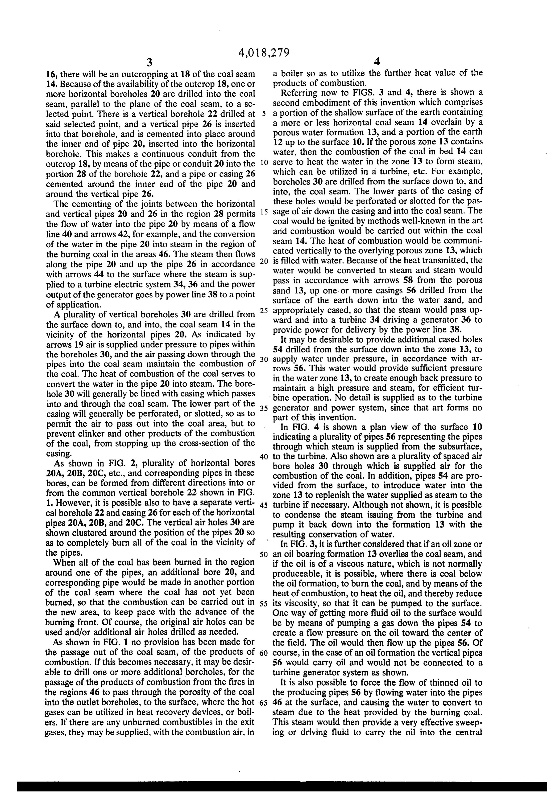
more horizontal boreholes 20 are drilled into the coal Referring now to FIGS. 3 and 4, there is shown a seam, parallel to the plane of the coal seam, to a se second embodiment of this invention which comprises lected point. There is a vertical borehole 22 drilled at 5 a portion of the shallow surface of the earth containing said selected point, and a vertical pipe 26 is inserted a more or less horizontal coal seam 14 overlain by a into that borehole, and is cemented into place around porous water formation 13, and a portion of the earth the inner end of pipe 20, inserted into the horizontal 12 up to the surface 10. If the porous zone 13 contains borehole. This makes a continuous conduit from the water, then the combustion of the coal in bed 14 can outcrop 18, by means of the pipe or conduit 20 into the 10 serve to heat the water in the Zone 13 to form steam, portion 28 of the borehole 22, and a pipe or casing 26 which can be utilized in a turbine, etc. For example, cemented around the inner end of the pipe 20 and boreholes 30 are drilled from the surface down to, and around the vertical pipe 26. into, the coal seam. The lower parts of the casing of The cementing of the joints between the horizontal these holes would be perforated or slotted for the pas and vertical pipes 20 and 26 in the region 28 permits 15 sage of air down the casing and into the coal seam. The the flow of water into the pipe 20 by means of a flow and coal would be ignited by methods well-known in the art line 40 and arrows 42, for example, and the conversion seamcombustion
would be carried out within the coal heat of combustion would be communi of the water in the pipe 20 into steam in the region of the burning coal in the areas 46. The steam then flows 20 cated vertically to the overlying porous zone 13, which is filled with water. Because of the heat transmitted, the along the pipe 20 and up the pipe 26 in accordance water with arrows 44 to the surface where the steam is sup pass inwould be converted to steam and steam would accordance with arrows 58 from the porous plied to a turbine electric system 34, 36 and the power sand 13, up one or more output of the generator goes by power line 38 to a point surface of the earth downcasings 56 drilled from the into the water sand, and of application.
A plurality of vertical boreholes 30 are drilled from 25 appropriately cased, so that the steam would pass up the surface down to, and into, the coal seam 14 in the ward and into a turbine 34 driving a generator 36 to vicinity of the horizontal pipes 20. As indicated by provide power for delivery by the power line 38. arrows 19 air is supplied under pressure to pipes within 54 drilledbefrom
It may desirable to provide additional cased holes the surface down into the zone 13, to the boreholes 30, and the air passing down through the pipes into the coal seam maintain the combustion of 30 supply water under pressure, in accordance with ar rows 56. This water would provide sufficient pressure the coal. The heat of combustion of the coal serves to in the water Zone 13, to create enough back pressure to convert the water in the pipe 20 into steam. The bore maintain a high pressure and steam, for efficient tur hole 30 will generally be lined with casing which passes bine operation. No detail is supplied as to the turbine into and through the coal seam. The lower part of the 35 generator and power casing will generally be perforated, or slotted, so as to part of this invention. system, since that art forms no permit the air to pass out into the coal area, but to In FIG. 4 is shown a plan view of the surface 10 prevent clinker and other products of the combustion indicating a plurality of pipes 56 representing the pipes of the coal, from stopping up the cross-section of the through which steam is supplied from the subsurface, casing. 40 to the turbine. Also shown are a plurality of spaced air As shown in FIG. 2, plurality of horizontal bores bore holes 30 through which is supplied air for the 20A, 20B, 20O, etc., and corresponding pipes in these combustion of the coal. In addition, pipes 54 are pro bores, can be formed from different directions into or vided from the surface, to introduce water into the from the common vertical borehole 22 shown in FIG. zone 13 to replenish the water supplied as steam to the 1. However, it is possible also to have a separate verti 45 turbine if necessary, Although not shown, it is possible cal borehole 22 and casing 26 for each of the horizontal to condense the steam issuing from the turbine and pipes 20A, 20B, and 200. The vertical air holes 30 are pump it back down into the formation 13 with the shown clustered around the position of the pipes 20 so resulting conservation of water.
as to completely burn all of the coal in the vicinity of In FIG. 3, it is further considered that if an oil zone or the pipes. 50 an oil bearing formation 13 overlies the coal seam, and When all of the coal has been burned in the region if the oil is of a viscous nature, which is not normally around one of the pipes, an additional bore 20, and produceable, it is possible, where there is coal below corresponding pipe would be made in another portion the oil formation, to burn the coal, and by means of the of the coal seam where the coal has not yet been heat of combustion, to heat the oil, and thereby reduce burned, so that the combustion can be carried out in 55 its viscosity, so that it can be pumped to the surface. the new area, to keep pace with the advance of the One way of getting more fluid oil to the surface would burning front. Of course, the original air holes can be be by means of pumping a gas down the pipes 54 to used and/or additional air holes drilled as needed, create a flow pressure on the oil toward the center of As shown in FIG. 1 no provision has been made for the field. The oil would then flow up the pipes 56. Of the passage out of the coal seam, of the products of 60 course, in the case of an oil formation the vertical pipes combustion. If this becomes necessary, it may be desir 56 would carry oil and would not be connected to a able to drill one or more additional boreholes, for the turbine generator system as shown. passage of the products of combustion from the fires in It is also possible to force the flow of thinned oil to the regions 46 to pass through the porosity of the coal the producing pipes 56 by flowing water into the pipes into the outlet boreholes, to the surface, where the hot 65 46 at the surface, and causing the water to convert to gases can be utilized in heat recovery devices, or boil steam due to the heat provided by the burning coal. ers. If there are any unburned combustibles in the exit This steam would then provide a very effective sweep gases, they may be supplied, with the combustion air, in ing or driving fluid to carry the oil into the central
Page 7
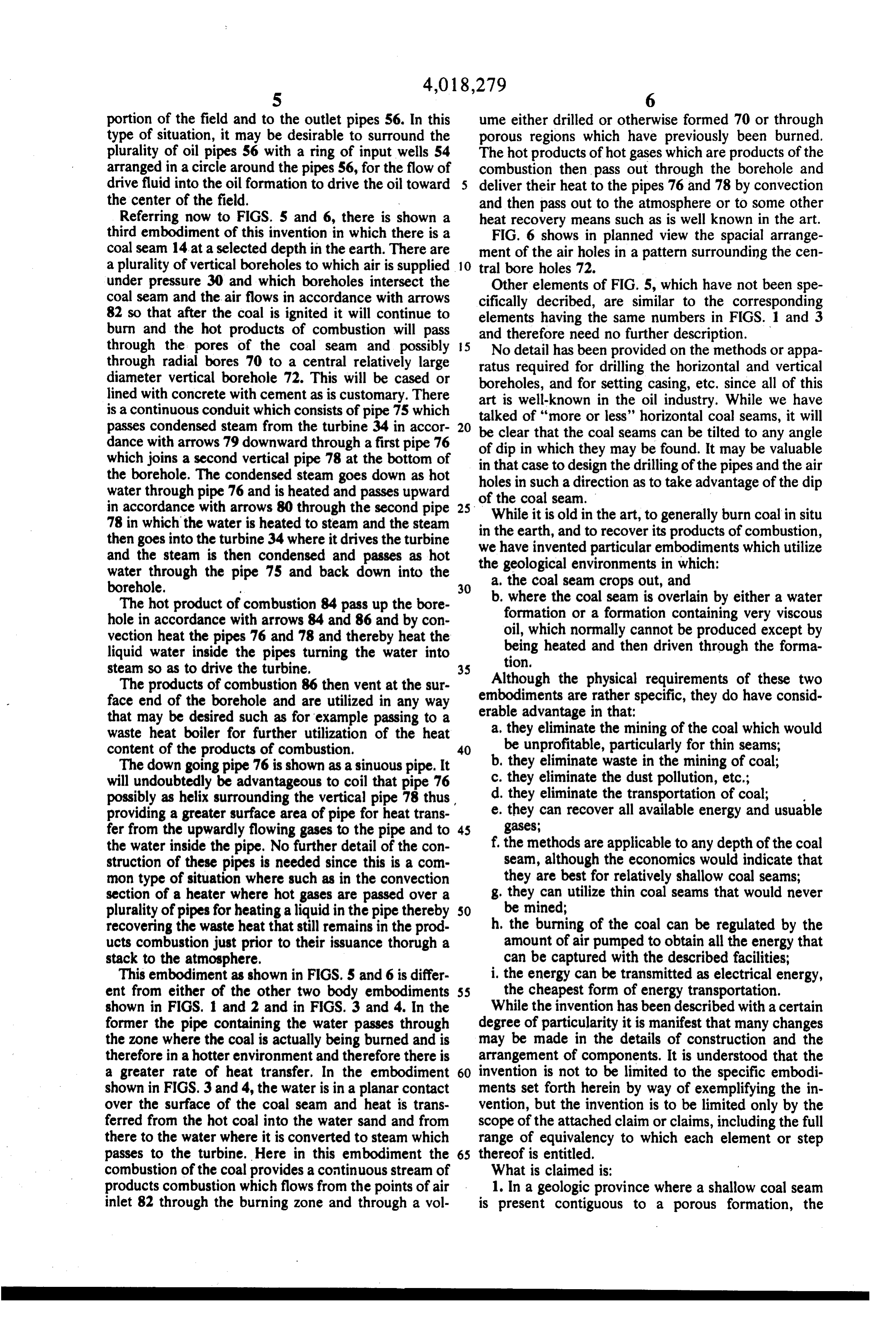
portion of the field and to the outlet pipes 56. In this ume either drilled or otherwise formed 70 or through type of situation, it may be desirable to surround the porous regions which have previously been burned. plurality of oil pipes 56 with a ring of input wells 54 The hot products of hot gases which are products of the arranged in a circle around the pipes 56, for the flow of combustion then pass out through the borehole and drive fluid into the oil formation to drive the oil toward 5 deliver their heat to the pipes 76 and 78 by convection the center of the field. W and then pass out to the atmosphere or to some other Referring now to FIGS. 5 and 6, there is shown a heat recovery means such as is well known in the art. third embodiment of this invention in which there is a FIG. 6 shows in planned view the spacial arrange coal seam 14 at a selected depth in the earth. There are ment of the air holes in a pattern surrounding the cen a plurality of vertical boreholes to which air is supplied 10 tral bore holes 72.
under pressure 30 and which boreholes intersect the Other elements of FIG. 5, which have not been spe coal seam and the air flows in accordance with arrows cifically decribed, are similar to the corresponding 82 so that after the coal is ignited it will continue to elements having the same numbers in FIGS. 1 and 3 burn and the hot products of combustion will pass through the pores of the coal seam and possibly 5 andNotherefore need no further description. detail has been provided on the methods or appa through radial bores 70 to a central relatively large ratus required for drilling the horizontal and vertical diameter vertical borehole 72. This will be cased or boreholes, and for setting casing, etc. since all of this lined with concrete with cement as is customary. There art is well-known in the oil industry. While we have is a continuous conduit which consists of pipe 75 which passes condensed steam from the turbine 34 in accor 20 talked of "more or less' horizontal coal seams, it will dance with arrows 79 downward through a first pipe 76 of dip in that be clear the coal seams can be tilted to any angle which they may be found. It may be valuable which joins a second vertical pipe 78 at the bottom of in that case to design the drilling of the pipes and the air the borehole. The condensed steam goes down as hot holes in such a direction as to take advantage of the dip water through pipe 76 and is heated and passes upward of the coal seam.
in accordance with arrows 80 through the second pipe 25
While it is old in the art, to generally burn coal in situ 78 in which the water is heated to steam and the steam then goes into the turbine 34 where it drives the turbine we in the earth, and to recover its products of combustion, and the steam is then condensed and passes as hot the have invented particular embodiments which utilize geological environments in which:
water through the pipe 75 and back down into the borehole. 30 a. the coal seam crops out, and The hot product of combustion 84 pass up the bore b. where the coal seam is overlain by either a water hole in accordance with arrows 84 and 86 and by con formation or a formation containing very viscous vection heat the pipes 76 and 78 and thereby heat the oil, which normally cannot be produced except by liquid water inside the pipes turning the water into being heated and then driven through the forma steam so as to drive the turbine, 35 tion.
The products of combustion 86 then vent at the sur embodimentsAlthough the physical requirements of these two face end of the borehole and are utilized in any way are rather specific, they do have consid that may be desired such as for example passing to a erable advantage in that:
a. they eliminate the mining of the coal which would waste heat boiler for further utilization of the heat content of the products of combustion. 40 be unprofitable, particularly for thin seams; The down going pipe 76 is shown as a sinuous pipe. It b, they eliminate waste in the mining of coal; will undoubtedly be advantageous to coil that pipe 76 c. they eliminate the dust pollution, etc.; possibly as helix surrounding the vertical pipe 78 thus d. they eliminate the transportation of coal; providing a greater surface area of pipe for heat trans e. they can recover all available energy and usuable fer from the upwardly flowing gases to the pipe and to 45 gases;
the water inside the pipe. No further detail of the con f, the methods are applicable to any depth of the coal struction of these pipes is needed since this is a com seam, although the economics would indicate that mon type of situation where such as in the convection they are best for relatively shallow coal seams; section of a heater where hot gases are passed over a g, they can utilize thin coal seams that would never plurality of pipes for heating a liquid in the pipe thereby 50 be mined;
recovering the waste heat that still remains in the prod h, the burning of the coal can be regulated by the ucts combustion just prior to their issuance thorugh a amount of air pumped to obtain all the energy that stack to the atmosphere. can be captured with the described facilities; This embodiment as shown in FGS. 5 and 6 is differ. i. the energy can be transmitted as electrical energy, ent from either of the other two body embodiments 55 the cheapest form of energy transportation. shown in FIGS. 1 and 2 and in FGS. 3 and 4. In the While the invention has been described with a certain former the pipe containing the water passes through degree of particularity it is manifest that many changes the zone where the coal is actually being burned and is may be made in the details of construction and the therefore in a hotter environment and therefore there is arrangement of components. It is understood that the a greater rate of heat transfer. In the embodiment 60 invention is not to be limited to the specific embodi shown in FIGS. 3 and 4, the water is in a planar contact ments set forth herein by way of exemplifying the in over the surface of the coal seam and heat is trans vention, but the invention is to be limited only by the ferred from the hot coal into the water sand and from scope of the attached claim or claims, including the full there to the water where it is converted to steam which range of equivalency to which each element or step passes to the turbine. Here in this embodiment the 65 thereof is entitled.
combustion of the coal provides a continuous stream of What is claimed is:
products combustion which flows from the points of air 1. In a geologic province where a shallow coal seam inlet 82 through the burning zone and through a vol is present contiguous to a porous formation, the
Page 8
method of burning the coal in situ and recovering the viscous oil, the method of burning the coal in situ and heat of combustion, comprising: recovering at least part of the heat of combustion, a drilling one or more vertical first boreholes from comprising:
a drilling one or more vertical first boreholes from the surface through said porous formation and into the surface through said porous formation and into said coal seam igniting said coal, and supplying air 5 said coal seam, igniting said coal, and supplying air under pressure through said boreholes to maintain under pressure to maintain the combustion of said the combustion of said coal; coal; whereby heat will be transferred from said hot whereby heat will be transferred from said hot coal coal seam to said contiguous formation; seam to said contiguous porous formation;
b. drilling at least one vertical second borehole from 10 b. the drilling at least one vertical second borehole from surface to said porous formation, inserting a the surface to said porous formation and flowing first casing into said second borehole; water under pressure into said porous formation; c. drilling at least one vertical third borehole from the whereby said water will be heated to steam; and surface to said porous formation and flowing a c. drilling at least one vertical third borehole from the driving fluid under pressure into said heated porous surface to said porous formation, inserting a first 5 formation;
casing into said third borehole, and connecting said whereby said viscous oil will be thinned, by said first casing to a steam energy utilization means and transferred heat, and said driving fluid will force simultaneously utilize the heat energy in said the thinned oil to said first casing to the surface and Steam.
20 said heat transferred from said burning coal will be 2. The method as in claim 1 including the step of: utilized.
d. drilling at least one fourth borehole from the sur 4. The method as in claim 3 including the step of: face into said coal formation, in the vicinity of said d. drilling at least one foruth borehole from the sur first boreholes, whereby the products of combus face into said coal formation, in the vicinity of said tion of said coal will flow up said fourth borehole to 25 first boreholes, whereby the products of combus the surface; and tion of said coal will flow up said fourth borehole to e. utilizing said products of combustion. the surface; and 3. In a geologic province where a shallow coal seam e. utilizing said products
of combustion.
is present, contiguous to a porous formation containing
Provenance
- Collection
- Cited prior art
- Original PDF
- patentimages.storage.googleapis.com →
- Filed
- 1975-11-12
- Pages
- 8
- Method
- pdftotext (the PDF's own text layer) + pdftoppm 300dpi page scans
- Source
- Google Patents bibliographic record
- Granted
- 1977-04-19
- Inventors
- Merrill J. Reynolds; Ralph W. Disney
- Transcribed from
- patentimages.storage.googleapis.com →