patent · US2994377
In situ combustion in carbonaceous strata
1 August 1961
Page 1 — bibliographic record
Aug. 1, 1961 J. C. TRANTHAM 2,994,377
IN SITU COMBUSTION IN CARBONACEOUS STRATA
Filed March 24, 1958
PRODUCTION
Fis
OBSERVATION
WELS
IGNITION
NN 1.4 sNN
NIFF
NLA,
4. 4. INVENTOR.
J. C. TRANTHAM
ATTORNEYs
Page 2
United States Patent Office 2,994,377 Patiented Aug. 1, 1961
reached and until all of the water is boiled off. This may 2,994,377 be too long a time in most cases and the combustion front N STU COMBUSTION IN CARBONACEOUS may pass the temperature-indicating hole before all of the
STRATA
Joseph C. Trantham, Bartlesville, Okla., assignor to Phil Water is boiled away.
lips Petroleum Company, a corporation of Delaware Accordingly, it is an object of the invention to provide Fied Mar. 24, 1958, Ser. No. 723,436 an improved process for effecting in situ combustion of 5 Claims. (C. 166-11) carbonaceous material in a stratum containing same to produce hydrocarbons therefrom. Another object is to
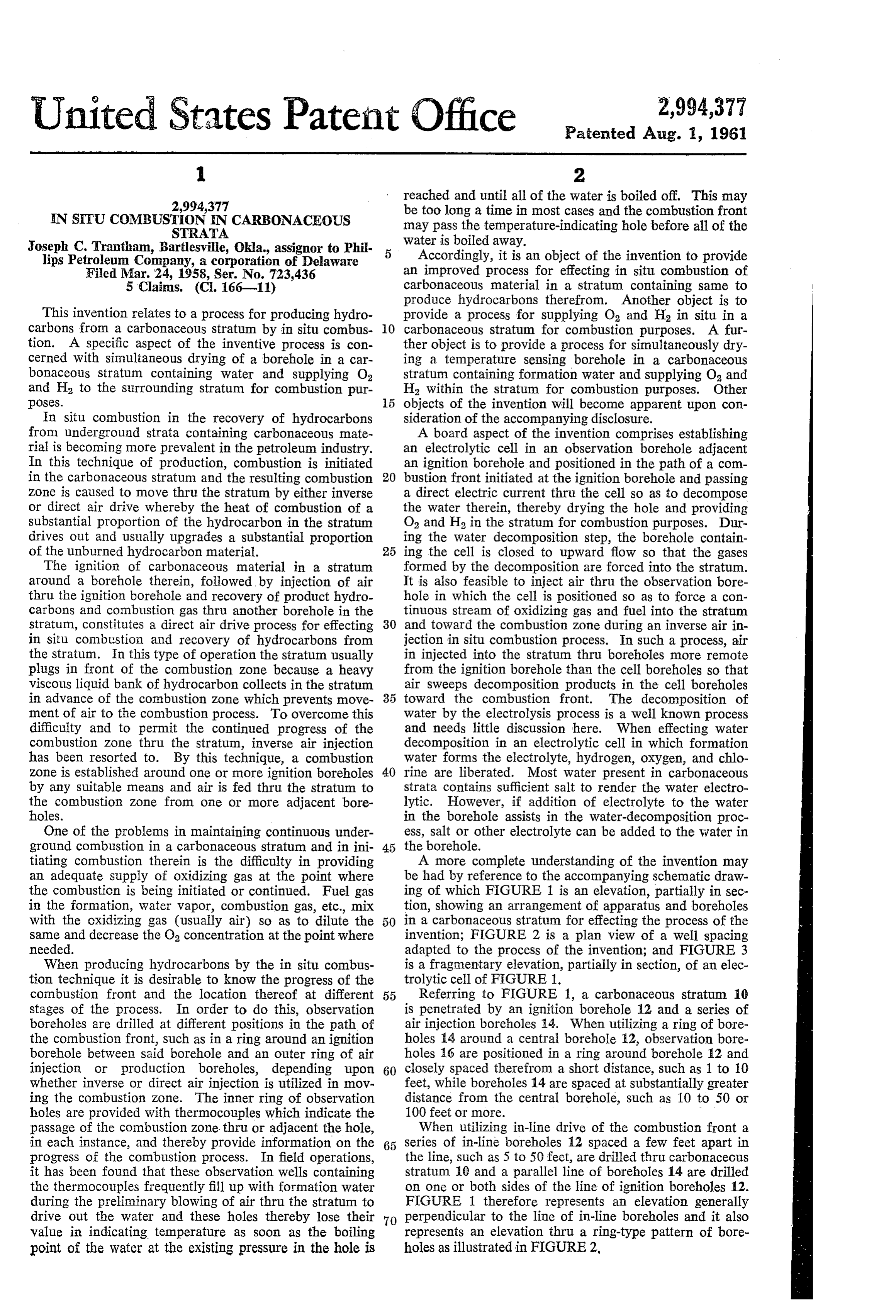
This invention relates to a process for producing hydro provide a process for supplying O2 and H2 in situ in a carbons from a carbonaceous stratum by in situ combus O carbonaceous stratum for combustion purposes. A fur tion. A specific aspect of the inventive process is con ther object is to provide a process for simultaneously dry cerned with simultaneous drying of a borehole in a car ing a temperature sensing borehole in a carbonaceous bonaceous stratum containing water and supplying O stratum containing formation water and supplying Oa and and H2 to the Surrounding stratum for combustion pur H2 within the stratum for combustion purposes. Other poses. 5 objects of the invention will become apparent upon con In situ combustion in the recovery of hydrocarbons sideration of the accompanying disclosure. from underground strata containing carbonaceous mate A board aspect of the invention comprises establishing rial is becoming more prevalent in the petroleum industry. an electrolytic cell in an observation borehole adjacent In this technique of production, combustion is initiated an ignition borehole and positioned in the path of a com in the carbonaceous stratum and the resulting combustion 20 bustion front initiated at the ignition borehole and passing Zone is caused to move thru the stratum by either inverse a direct electric current thru the cell so as to decompose or direct air drive whereby the heat of combustion of a the water therein, thereby drying the hole and providing Substantial proportion of the hydrocarbon in the stratum O2 and H2 in the stratum for combustion purposes. Dur drives out and usually upgrades a substantial proportion ing the water decomposition step, the borehole contain of the unburned hydrocarbon material. 25 ing the cell is closed to upward flow so that the gases The ignition of carbonaceous material in a stratum formed by the decomposition are forced into the stratum. around a borehole therein, followed by injection of air It is also feasible to inject air thru the observation bore thru the ignition borehole and recovery of product hydro hole in which the cell is positioned so as to force a con carbons and combustion gas thru another borehole in the tinuous stream of oxidizing gas and fuel into the stratum stratum, constitutes a direct air drive process for effecting 30 and toward the combustion Zone during an inverse air in in situ combustion and recovery of hydrocarbons from jection in situ combustion process. In such a process, air the stratum. In this type of operation the stratum usually in injected into the stratum thru boreholes more remote plugs in front of the combustion zone because a heavy from the ignition borehole than the cell boreholes so that viscous liquid bank of hydrocarbon collects in the stratum air Sweeps decomposition products in the cell boreholes in advance of the combustion zone which prevents move 35 toward the combustion front. The decomposition of ment of air to the combustion process. To overcome this Water by the electrolysis process is a well known process difficulty and to permit the continued progress of the and needs little discussion here. When effecting water combustion Zone thru the stratum, inverse air injection decomposition in an electrolytic cell in which formation has been resorted to. By this technique, a combustion water forms the electrolyte, hydrogen, oxygen, and chlo Zone is established around one or more ignition boreholes 40 rine are liberated. Most water present in carbonaceous by any suitable means and air is fed thru the stratum to strata contains sufficient salt to render the water electro the combustion Zone from one or more adjacent bore lytic. However, if addition of electrolyte to the water holes. in the borehole assists in the water-decomposition proc One of the problems in maintaining continuous under ess, salt or other electrolyte can be added to the water in ground combustion in a carbonaceous stratum and in ini 45 the borehole.
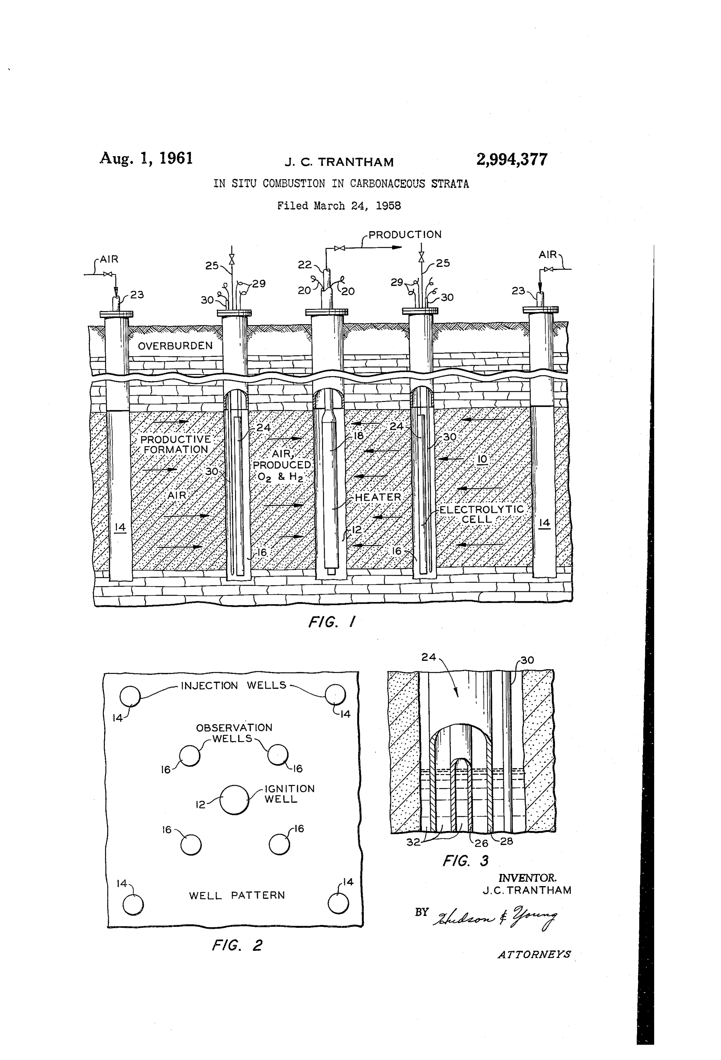
tiating combustion therein is the difficulty in providing A more complete understanding of the invention may an adequate Supply of oxidizing gas at the point where be had by reference to the accompanying schematic draw the combustion is being initiated or continued. Fuel gas ing of which FIGURE 1 is an elevation, partially in sec in the formation, water vapor, combustion gas, etc., mix tion, showing an arrangement of apparatus and boreholes with the oxidizing gas (usually air) so as to dilute the 50 in a carbonaceous stratum for effecting the process of the Sane and decrease the O2 concentration at the point where invention; FIGURE 2 is a plan view of a well spacing needed. adapted to the process of the invention; and FIGURE 3 When producing hydrocarbons by the in situ combus is a fragmentary elevation, partially in section, of an elec tion technique it is desirable to know the progress of the trolytic cell of FIGURE 1.
combustion front and the location thereof at different 55 Referring to FIGURE 1, a carbonaceous stratum 10 stages of the process. In order to do this, observation is penetrated by an ignition borehole 2 and a series of boreholes are drilled at different positions in the path of air injection boreholes 14. When utilizing a ring of bore the combustion front, such as in a ring around an ignition holes 4 around a central borehole 2, observation bore borehole between said borehole and an outer ring of air holes 16 are positioned in a ring around borehole 2 and injection or production boreholes, depending upon 60 closely spaced therefrom a short distance, such as 1 to 10 whether inverse or direct air injection is utilized in mov feet, while boreholes 14 are spaced at substantially greater ing the combustion Zone. The inner ring of observation distance from the central borehole, such as 10 to 50 or holes are provided with thermocouples which indicate the 100 feet or more.
passage of the combustion Zone thru or adjacent the hole, When utilizing in-line drive of the combustion front a in each instance, and thereby provide information on the 65 series of in-line boreholes 12 spaced a few feet apart in progress of the combustion process. In field operations, the line, such as 5 to 50 feet, are drilled thru carbonaceous it has been found that these observation wells containing stratum 10 and a parallel line of boreholes 14 are drilled the thermocouples frequently fill up with formation water on one or both sides of the line of ignition boreholes 12. during the preliminary blowing of air thru the stratum to FIGURE 1 therefore represents an elevation generally drive out the water and these holes thereby lose their 70 perpendicular to the line of in-line boreholes and it also value in indicating temperature as soon as the boiling represents an elevation thru a ring-type pattern of bore point of the water at the existing pressure in the hole is holes as illustrated in FIGURE 2,
Page 3
Ignition borehole 12 is provided with a heater 18 which the borehole. This should occur before the combustion may be an electric heater connected by wires 20 to a zone reaches the observation well. Suitable source of current, or a gas-fired heater, or a mass To illustrate the invention, when a 6 volt direct cur of incandescent charcoal, or other suitable heating device rent is applied to a cell 12 feet long comprising a 4 inch for raising the temperature of the adjacent stratum to O.D., 3% inch I.D. outer electrode of porous graphite, the ignition point of the carbonaceous material therein and a Smaller hollow porous graphite cylindrical inner when contacted with air or other combustion-supporting electrode of 2 inch O.D. and 1% inch I.D., positioned gas. Well tubing 22 extends to the bottom of borehole axially in a 6 inch diameter borehole filled with forma 12 for withdrawing product hydrocarbons, combustion tion salt water to the top of the cell, about 208 standard gas, etc., in conventional manner. Observation boreholes 10 cubic feet of H and about 104 s.c.f. of O. are liberated 16 are provided with electrolytic cells comprising an per foot of depth with an expenditure of approximately anode 26 and cathode 28 (FIGURE 3) connected by 42.4 kw.h. of electrical energy. Chlorine production leads 29 with any suitable source of direct electric current amounts to about 0.064 s.c.f. per foot of depth when the (not shown). A gasoline, diesel, or propane operated concentration of NaCl is 2,000 p.p.m. and 0.64 s.c.f. with motor driving a low voltage, high current D.C. genera a concentration of 20,000 p.p.m. tor (e.g., an electric weider) is an excellent source of Certain modifications of the invention will become current. Each of boreholes 16 is also provided with a apparent to those skilled in the art and the illustrative thermocouple 30 or other temperature sensing device. details disclosed are not to be construed as imposing un Anode 26 may be constructed in the form of a solid necessary limitations on the invention.
rod of graphite or magnetite or in the form of a hollow I claim:
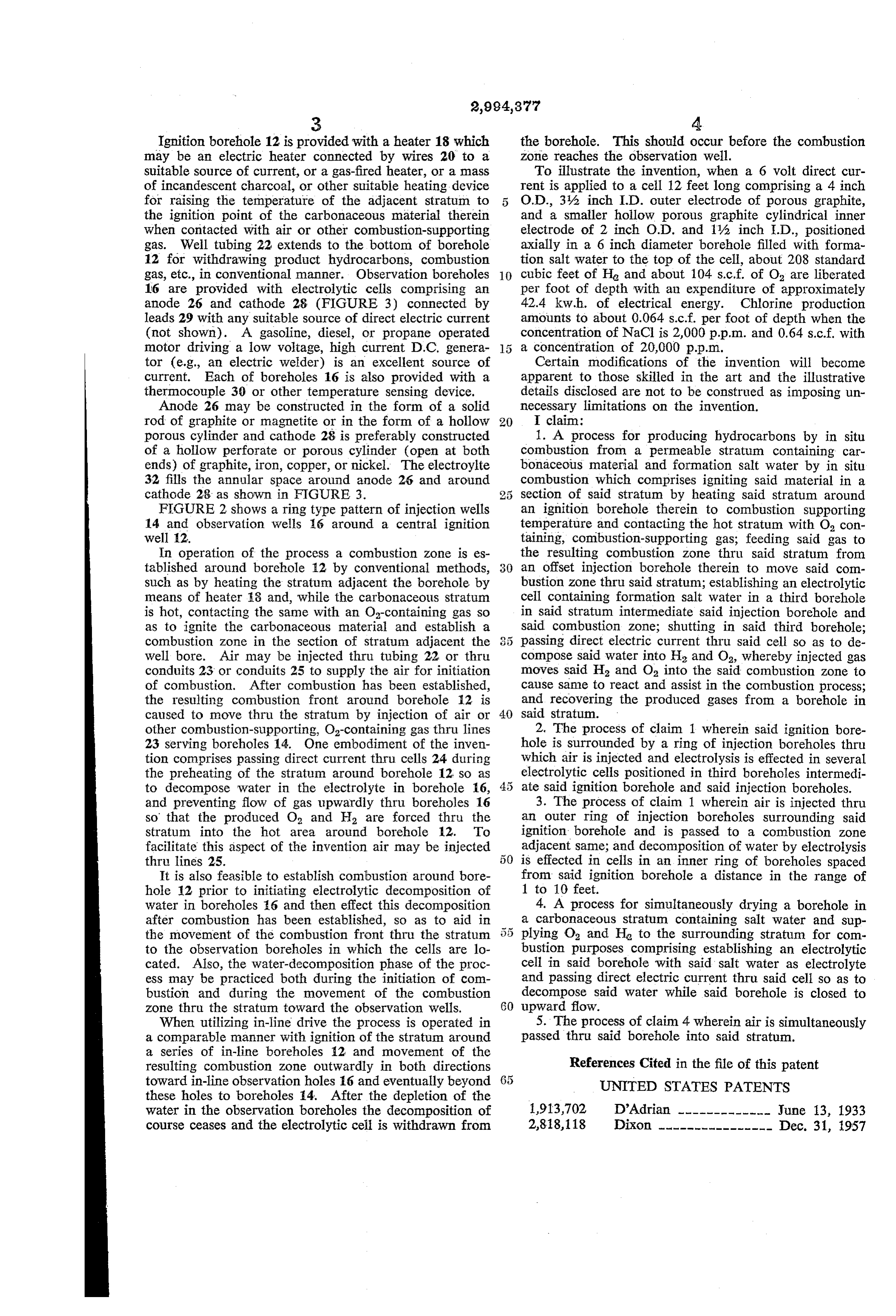
porous cylinder and cathode 28 is preferably constructed 1. A process for producing hydrocarbons by in situ of a hollow perforate or porous cylinder (open at both combustion from a permeable stratum containing car ends) of graphite, iron, copper, or nickel. The electroylte bonaceous material and formation salt water by in situ 32 fills the annular space around anode 26 and around combustion which comprises igniting said material in a cathode 28 as shown in FIGURE 3. 2.5 Section of said stratum by heating said stratum around FIGURE 2 shows a ring type pattern of injection wells an ignition borehole therein to combustion supporting 14 and observation wells 6 around a central ignition temperature and contacting the hot stratum with O. con well 2. taining, combustion-supporting gas; feeding said gas to In operation of the process a combustion zone is es the resulting combustion zone thru said stratum from tablished around borehole 2 by conventional methods, 30 an offset injection borehole therein to move said com Such as by heating the stratum adjacent the borehole by bustion Zone thru said stratum; establishing an electrolytic means of heater 8 and, while the carbonaceous stratum cell containing formation salt water in a third borehole is hot, contacting the same with an O-containing gas so in said stratum intermediate said injection borehole and as to ignite the carbonaceous material and establish a said combustion zone; shutting in said third borehole; combustion zone in the section of stratum adjacent the 3 5 passing direct electric current thru said cell so as to de well bore. Air may be injected thru tubing 22 or thru compose said water into H and O2, whereby injected gas conduits 23 or conduits 25 to supply the air for initiation moves said H2 and Oa into the said combustion zone to of combustion. After combustion has been established, cause same to react and assist in the combustion process; the resulting combustion front around borehole 12 is and recovering the produced gases from a borehole in caused to move thru the stratum by injection of air or 40 said stratum.
other combustion-supporting, O-containing gas thru lines 2. The process of claim 1 wherein said ignition bore 23 serving boreholes 14. One embodiment of the inven hole is surrounded by a ring of injection boreholes thru tion comprises passing direct current thru cells 24 during which air is injected and electrolysis is effected in several the preheating of the stratum around borehole 12 so as electrolytic cells positioned in third boreholes intermedi to decompose water in the electrolyte in borehole 6, ate said ignition borehole and said injection boreholes. and preventing flow of gas upwardly thru boreholes 16 3. The process of claim 1 wherein air is injected thru so that the produced O and H2 are forced thru the an outer ring of injection boreholes surrounding said stratum into the hot area around borehole 12, To ignition borehole and is passed to a combustion zone facilitate this aspect of the invention air may be injected adjacent same; and decomposition of water by electrolysis thru lines 25. is effected in cells in an inner ring of boreholes spaced It is also feasible to establish combustion around borefrom said ignition borehole a distance in the range of hole 12 prior to initiating electrolytic decomposition of 1 to 10 feet.
water in boreholes 6 and then effect this decomposition 4. A process for simultaneously drying a borehole in after combustion has been established, so as to aid in a carbonaceous stratum containing salt water and sup the movement of the combustion front thru the stratum 5 5 plying Oa and Ho to the surrounding stratum for com to the observation boreholes in which the cells are lo bustion purposes comprising establishing an electrolytic cated. Also, the water-decomposition phase of the proc cell in said borehole with said salt water as electrolyte ess may be practiced both during the initiation of com and passing direct electric current thru said cell so as to bustion and during the movement of the combustion decompose said water while said borehole is closed to Zone thru the stratum toward the observation wells. 60 upward flow.
When utilizing in-line drive the process is operated in 5. The process of claim 4 wherein air is simultaneously a comparable manner with ignition of the stratum around passed thru said borehole into said stratum. a series of in-line boreholes 2 and movement of the resulting combustion Zone outwardly in both directions References Cited in the file of this patent toward in-line observation holes 16 and eventually beyond UNITED STATES PATENTS these holes to boreholes 4. After the depletion of the water in the observation boreholes the decomposition of 1913,702 D'Adrian ------------- June 13, 1933 course ceases and the electrolytic cell is withdrawn from 2,818,118 Dixon ---------------- Dec. 31, 1957
Provenance
- Collection
- Cited prior art
- Original PDF
- patentimages.storage.googleapis.com →
- Filed
- 1958-03-24
- Pages
- 3
- Method
- pdftotext (the PDF's own text layer) + pdftoppm 300dpi page scans
- Source
- Google Patents bibliographic record
- Granted
- 1961-08-01
- Inventors
- Joseph C Trantham; Phillips Petroleum Co
- Transcribed from
- patentimages.storage.googleapis.com →