patent · US3993122
Steps, stairs and the like
23 November 1976
Page 1 — bibliographic record
United States Patent (19) [11] 3,993,122 Svenstam (45) Nov. 23, 1976 (54) STEPS, STARS AND THE LIKE 1,771,268 7/1930 Musgrave.............................. 404/71 (75) inventor: Syen Gunnar Svenstam, Upplands
Vasby, Sweden
3,157,358 11/1964 Birkemeier............................. 237/1
73) Assignee: Granges Essem Aktiebolag, FOREIGN PATENTS OR APPLICATIONS Vasteras, Sweden 236,086 10/1964 Austria............... .......... 52/189 22 Filed: Sept. 24, 1975 535,480 2/1955 Belgium................................ 52/220 481,691 3/1952 Canada................................. 165/45 (21) Appl. No.: 616,397 702,077 l/1965 Canada................................. 404/71 Related U.S. Application Data 172,886 9/1960 Sweden................................. 52/182 (63) Continuation-in-part of Ser. Nos. 284,456, Aug. 28, Primary Examiner-Martin P. Schwadron 1972, Pat. No. 3,881,235, and Ser. No. 462,538, Assistant Examiner-Abraham Hershkovitz April 19, 1974, abandoned. Attorney, Agent, or Firm-Haseltine, Lake & Waters 30 Foreign Application Priorityy Data gn App 57 ABSTRACT
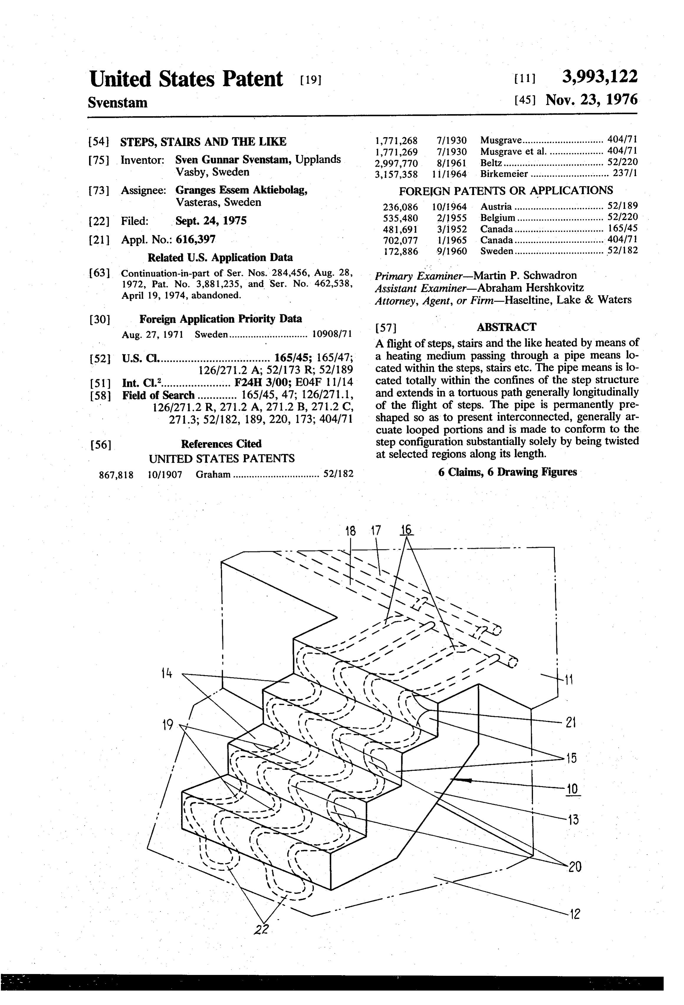
A flight of steps, stairs and the like heated by means of 52 U.S. Cl..................................... 165/45; 165/47; a heating medium passing through a pipe means lo 126/271.2 A, 52/173 R; 52/189 cated within the steps, stairs etc. The pipe means is lo 51) Int. Cl.'....................... F24H 3/00; E04F 1 1/14 cated totally within the confines of the step structure 58 Field of Search............. 165/45, 47; 126/271.1, and extends in a tortuous path generally longitudinally 126/271.2 R, 271.2 A, 271.2 B, 271.2 C, of the flight of steps. The pipe is permanently pre 271.3; 52/182, 189,220, 173; 404/71 shaped so as to present interconnected, generally ar cuate looped portions and is made to conform to the 56 References Cited step configuration substantially solely by being twisted UNITED STATES PATENTS at selected regions along its length.
867,818 10/1907 Graham................................ 52/182 6 Claims, 6 Drawing Figures
Page 2
Drawing sheet — no readable text.
Page 3
Drawing sheet — no readable text.
Page 4
the accompanying drawing, further advantages and
STEPS, STAIRS AND THE LIKE features of the invention being made apparent in con nection therewith.
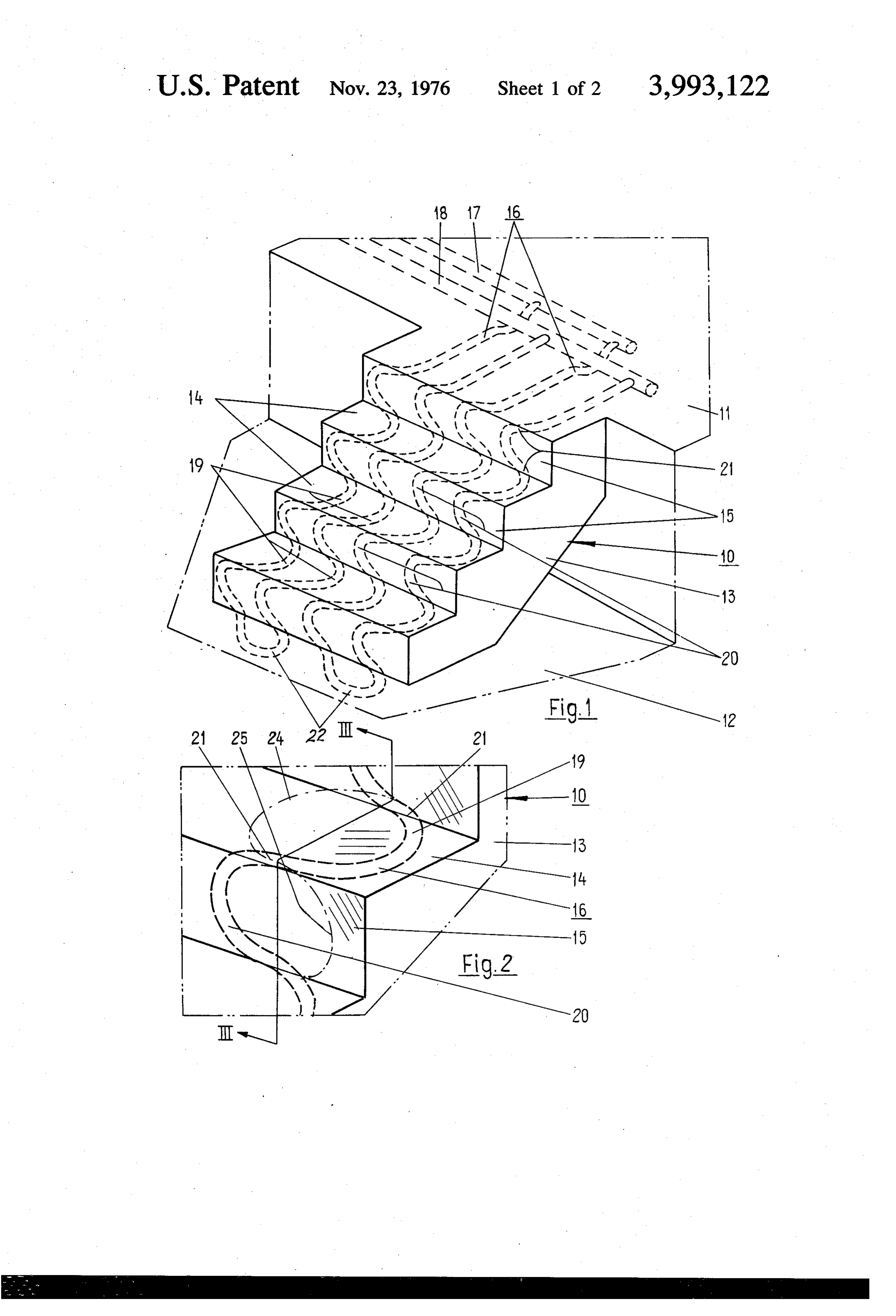
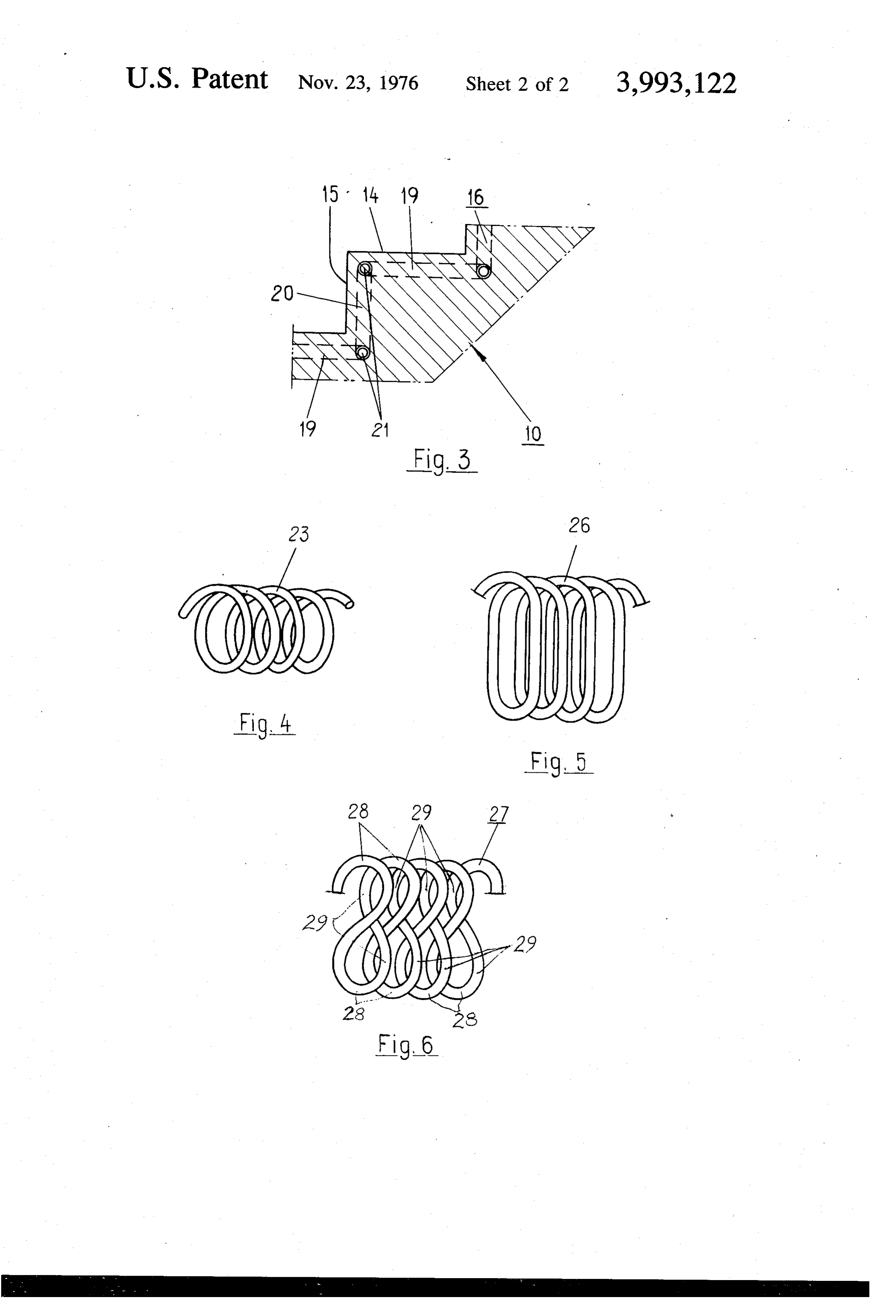
The present application is a continuation-in-part of BRIEF DESCRIPTION OF THE DRAWING the parent applications Ser. Nos. 284,456, filed Aug. 5 28, 1972 (now U.S. Pat. No. 3,881,235) and Ser. No. FIG. 1 is a perspective view of a flight of steps con 462,538, filed Apr. 19, 1974, now abandoned. structed in accordance with the invention; BACKGROUND OF THE INVENTION FIG. 2 illustrates in larger scale a portion of the steps shown in FIG. 1;
The present invention relates to a flight of steps, 10 FIG. 3 is a sectional view taken through line III-III stairs and the like of the type with which at least one in FIG. 2; and pipe, suitably made of a plastics material, is mounted FIGS. 4-6 illustrate in perspective three forms to beneath the treads of the flight of steps or stairs and which the pipes laid in the steps can be permanently arranged to conduct a heat transmitting medium to pre-shaped before being embodied in the steps. maintain the steps or stairs free from ice and snow. 5
When constructing steps or stairs of the aforemen DESCRIPTION OF THE PREFERRED tioned type, the pipe through which the heating me EMBODIMENTS dium is conducted is normally delivered to the working In the drawing like elements have been identified by site in the form of pipe which has been wound in a 20 like reference numerals, and the reference numeral 10 straight and cold condition onto drums or the like of indicates generally a flight of steps or stairs extending relatively large diameter, and hence from the point of between an upper platform level 11 and a lower plat view of laying the pipe, is equivalent to straight pipe. form level 12. The visible side of the steps is shown at Because of the relative inflexibility of the pipe, it is 13. Embodied in the steps 10, the treads are risers of normally necessary to place it on the structural mem which are shown at 14 and 15 respectively, are plastic bers of the steps, e.g. the step reinforcing frame struc 25 pipes 16 through which is arranged to pass a heating ture, in such a manner that portions of the pipe in the medium for the purpose of maintaining the steps free finished flight of steps extend traversely of the steps from ice and snow. The heating medium is suitably in beneath the treads, while other portions of the pipe the form of hot water, which may previously have been connecting together the transversely extending pipe used for heating houses, apartment buildings or the portions are located outside the steps in the form of 30 like.
wide connecting loops. The connecting loops must be One end of each pipe 16 is connected to an inlet 17 placed externally of the steps on either side thereof and and the other end to an outlet 18 for heating medium. fulfill no useful purpose other than that of connecting The pipes 16 extend generally in the longitudinal direc together the transversely extending pipe portions. This tion of the flight of steps 10 in such a tortuous path as method of construction often results in high building 35 to present within the confines of the steps substantially costs and excessively bulky step or stair structures. U-shaped interconnected looped portions 19, 20 which With another method of constructing steps or stairs extend alternately towards either side of the steps. of the aforementioned type, the system of pipes for Each of the looped portions 19, 20 is located in a plane conducting the heating medium is constructed of which lies generally parallel with the surface of its re straight lengths of pipe placed transversely and longitu 40 spective riser or tread, the looped portions located dinally of the flight of steps and connected together by beneath the tread surfaces 14 being identified by the means of pipe couplings or the like. Although this reference numeral 19 and the looped portions located method of construction enables the steps or stairs to be inwardly of the riser surface 15 with the reference kept within reasonable dimensions, the costs involved 45 numeral 20. The pipes 16 extend substantially perpen are high and the flow conditions for the heating me dicular to the longitudinal direction of the flight of dium unfavorable, while at the same time there is a steps 10 at the junctions 21 between the treads and serious danger of leaks occurring. risers. The pipes 16 are preshaped in a manner such It is an object of the present invention to overcome that they present interconnected, substantially arcuate the above disadvantages. portions of such shape and size as to render it unneces In accordance with the present invention, there is 50 sary to bend or straighten the arcuate portions, or at provided a flight of steps, stairs and the like having pipe least to more than a slight extent, in order to form the means arranged to conduct heating medium to main looped portions 19, 20 when mounting the pipes 16 on tain the steps free from ice and snow, said pipe means the building framework (not shown) of the steps. This being permanently pre-shaped to present intercon framework may comprise, for example, a reinforcing nected substantially arcuate portions and extending 55 frame structure for the steps or a stairlike body, on substantially in the longitudinal direction of the flight which the pipes are mounted and then embedded in the of steps in a tortuous path such as to present substan material forming the outer layer of the tread and riser. tially arcuate interconnected looped portions located The permanent shapes of the pipes 16 can readily be within the confines of the flight of steps and curving imparted thereto in manufacture, by shaping the pipes alternately towards either side of the flight of steps, said 60 while hot and cooling them in the shaped condition. pipe means being arranged beneath the treads and Shaping of the pipes can be effected at the pipe-making risers of the steps in planes extending substantially factory, in connection with the pipe extrusion process parallel with said treads and risers, said pipe means applied to produce the pipes. Alternately, it is often extending substantially perpendicular to the longitudi more suitable to shape ready manufactured pipes, for nal direction of said flight of steps at the junctions 65 example by passing hot water through the pipes so that between treads and risers. the pipes can be bent to the desired shape, and then The invention will now be described in more detail permanently fixing the shape by passing a cooling me with reference to an embodiment thereof illustrated in dium such as cold water through the pipes.
Page 5
According to the invention, pipes can be used which are selected so that the length of a turn is substantially have been permanently pre-shaped in a manner such equal to the total length of the looped portions 19, 20 that the pipes follow a substantially sinus-shaped path in a tread 14 and adjacent riser 15 of the finished steps. or a path of similar tortuous configuration so that the The permanently shaped pipe 26 illustrated in FIG. 5 pipes need generally only to be twisted through about differs from pipe 23 inasmuch as the turns of the pipe 90 around their axis in certain regions along the length 26 are oval and not circular. when using the pipe 26, thereof in order to be made to conform in the desired generally arcuate looped portions which correspond to manner to the step structure. Pipes in this form are less the looped portions 19, 20 but which extend to a suitable, however, from the point of view of general greater or lesser extent in the transverse direction of handling and transportation of the pipes. A more ad 10 the steps can be obtained by twisting the pipe through vantageous pipe form is described hereinafter with 90° around its long axis, at selected regions spaced reference to FIGS. 4-6. approximately 180° apart.
As will be seen from FIG. 1, the pipes 16 extend FIG. 6 illustrates a pipe 27 which has been perma parallel to one another, wherewith each tread and riser nently shaped to the form of sequentially arranged of the steps will be heated substantially uniformly 15 loops of roughly figure-eight configuration and which across the whole of its surface by the heating medium can be used with the present invention. When mount flowing through the pipes. Each pipe 16 passes back ing the pipe to the frame structure of the steps, the pipe wards and forwards once between the top 11 and the can be turned through 90 about its long axis at regions foot 12 of the steps 10, although it will be readily per 28 to obtain in each tread and riser two looped por ceived that each pipe 16 can form more than two pipe 20 tions, each of which extends towards its respective side sections extending between the stair-foot and the stair of the steps. Alternatively, the pipe 27 can be twisted at head. In this connection, it is suitable that the inlet 17 regions 29, wherewith the portions of the pipe forming and the outlet 18 are located in the illustrated manner three-quarters of the 8-shaped loops are placed be at the same end of the flight of steps, whereby the heat neath the treads 14 and the slightly S-shaped portions from the heating medium flowing through the pipes is 25 of distrubuted generally uniformly over the whole flight of 15.the pipe therebetween are placed behind the risers steps 10. The inlet 17 and outlet 18 arranged at the top The invention is not restricted to the described and platform surface 11 of the steps are joined to the pipes illustrated embodiment, but can be modified within the 16 by welding joints or pipe couplings (not shown), the pipe sections of each pipe 16 extending backwards and 30 scope of the following claims. I claim:
forwards between the foot and the head of the steps are 1. A flight of steps, stairs and the like having pipe located parallel with each other and are joined together means at the lower end of the steps by means of a looped tain thearranged to conduct heating medium to main portion 22 formed by a portion of the pipe 16 and being permanentlyfrom steps free ice and snow, said pipe means arranged beneath the bottom platform surface 12 of 35 nected substantiallypreshapedarcuate to present intercon portions and extending the steps. substantially in the longitudinal direction of the flight In FIG. 4 there is illustrated a helically wound, per of steps in a tortuous path such as to present substan manently shaped pipe 23, which is a suitable form from the aspect of transportation and handling of the pipe tially within arcuate interconnected looped portions located the confines of the flight of steps and curving and which can be used to advantage with a flight of 40 steps or stairs constructed in accordance with FIGS. alternately towards either side of the flight of steps, said 1-3. It will readily be understood that looped portions risers of the being pipe means arranged beneath the treads and steps in planes extending substantially similar to those at 19 and 20 can readily be obtained by parallel twisting the pipe 23 through roughly 90° about its long extendingwith said treads and risers, said pipe means substantially perpendicular to the longitudi axis at regions along the helically coiled pipe spaced 45 about 180° apart. This is also evident from FIG. 2, from nal direction of said flight of steps at the junctions between treads and risers.
which it can be seen that a turn of a helix would be obtained by turning the uppermost loop portion 20 2. The steps of claim 1, wherein said pipe means through 90 to the upper tread, as shown by the chain comprises a number of pipes extending in a tortuous path substantially in the longitudinally direction of the line 24, and that another turn of a helix would be ob 50 flight of steps, said pipes extending generally parallel tained if the lowermost loop portion 19 were also turned through 90° to the lower tread, as shown by the with each other along the flight of steps. chain line 25. If the depth of the tread exceeds the 3. The steps of claim 1, wherein said pipe means height of the riser to compensate for the difference the comprises a number of pipe portions extending in a arcuate pipe portions forming the looped portions in tortuous path substantially in the longitudinal direction the tread can be straightened out slightly and/or the 55 of the flight of steps between the top and the bottom arcuate pipe portions forming the looped portions in . thereof.
the risers may be more tightly bent, and/or a larger means 4. The steps of claim 3, wherein the ends of said pipe portion of each turn of the helically wound pipe may be are connected at one end and the same end of used to form the looped portions in the treads and a 60 the flight of steps to a heating medium inlet and a heat smaller portion of each turn may be used to form the ing medium outlet.
looped portions in the riser. When mounting the pipe 5. The steps of claim 3, wherein said pipe portions 23 on the step frame structure, it is also possible to extend substantially parallel with each other along the straighten or to bend the pipe somewhat, in a manner flight of steps.
to obtain in the finished flight of steps generally semi 6. The steps of claim 1, wherein said pipe means circular arcuate looped portions 19, 20 respectively of 65 extends between two adjacent treads and two adjacent risers respectively in the form of one single, substan greater and smaller radius than the radius of the coils of tially the helically wound pipe 23. Suitably, however, the U-shaped looped k portion.
dimensions of the turns of the helically wound pipe 23
Provenance
- Collection
- Cited prior art
- Original PDF
- patentimages.storage.googleapis.com →
- Filed
- 1975-09-24
- Pages
- 5
- Method
- pdftotext (the PDF's own text layer) + pdftoppm 300dpi page scans
- Source
- Google Patents bibliographic record
- Granted
- 1976-11-23
- Inventors
- Sven Gunnar Svenstam; Granges Essem AB
- Transcribed from
- patentimages.storage.googleapis.com →