patent · US1390258
Stepped lenticular system for heat and light concentrating to be used on flying-machines
6 September 1921
Page 1
350 a 4.52 SR -- -
STEPPED LENT CULAR SYSTEM FOR HEAT AND LIGHT CONCENTRATING TO BE USED 0N
APP. CATION FLED JUNE 8, 1920.
1,390,258. Patented Sept. 6, 1921.
PHILIPPE (ENESTE
Page 2
Drawing sheet — no readable text.
Page 3
UNITED STATES PATENT OFFICE.
PHILIPPE GENESTE, OF CHATEAU DE CHAPEAU CORNU, VIGNIEU, FRANCE,
STEPPED LENTICULAR SYSTEM FOR HEAT AND LIGHT CONCENTRATING To BE USED
1,390,258. Specification of Letters Patent, Patented Sept. 6, 1921. Application filed June 8, 1920. Serial No. 387,505.
To all whom it may concern: lators they may be used for detecting under Be it known that I, PHILIPPE GENESTE, a Sea boats and the like.
citizen of the French Republic, and resident The required temperature may be got in of Chateau de Chapeau Cornu, Vignieu, any particular case by flying at the required 5 Isère, France, have invented certain new and height. When the machine is flying at a 66 useful Improvements in Stepped Lenticular Small distance from the ground, the bundle Systems for Heat and Light Concentrating of calorific rays becomes larger, its tempera to be Used on Flying-Machines, for which I ture decreases.
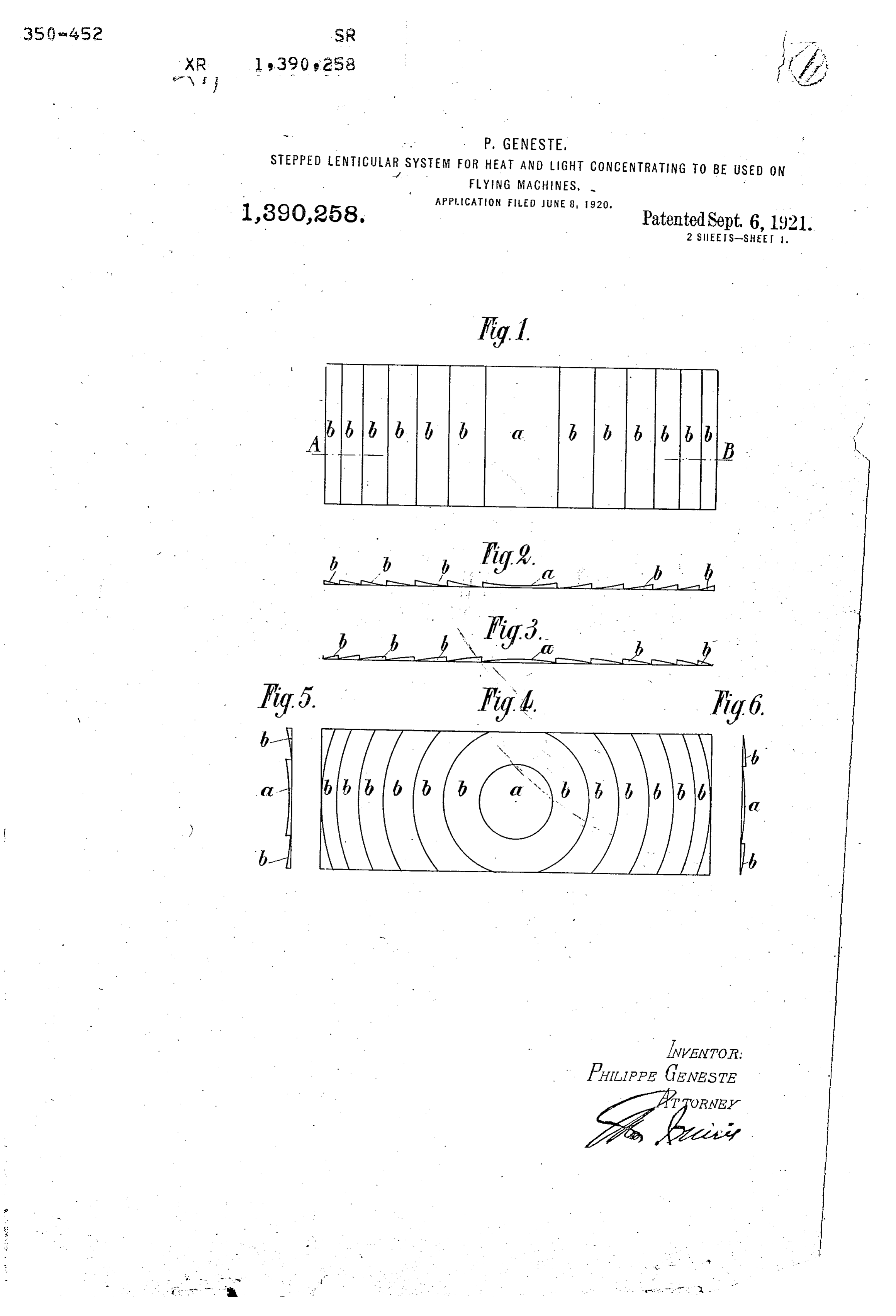
... , have filed an application in France April 12, Scientific experiments made by Buffon in P 1918, of which the following is a specifica France in 1745 with a lens of Om 60 diameter 65 --- - tion. having gradations, have proved that tem The present invention has for its object peratures of 2000 degrees C., may be at lenticular systems intended for being ap tained, whereby platinum and quartz are plied to the planes of flying machines, in melted. It may be understood that with 15 order to form an aerial heat and light ac lenses of two hundred times the cited dimen 70 cumulator, said lenticular systems compris sions, (admitting a flying machine of 20 ing spherical or cylindrical segments. meters span across the wings), very high ith this object in view the frame of the temperatures may be got. In a flying ma surface or plane, may be of wood or metal chine having 20 meters span, the rectangular 20 provided with transverse and longitudinal bundle of calorific rays emitted by the plane 75 bars and eventually with trelliswork and in system would have a length of 3 meters, the rectangular spaces thus formed the lens which would sweep over the objects on the segments are secured. ground during about to of a second, ac The lenticular systems intended to form an cording to the velocity of the flight. 25 aerial heat and light accumulator may be The device is shown by way of example in 80 composed of solid segments made of glass, the accompanying drawing, in which: crown glass, flint glass or the like or of hol Figure 1 is a plane view of a lenticular sys low transparent segments made of glass, cel term having cylindrical segments. luloid and the like and containing refractive Fig. 2 is a cross section on line A-B of a 30 liquids or gases.
Such segments may be of spherical or cy divergent while lenticular. system for light gases, 85 lindrical shape and have a convenient curva Fig. 3 is a cross section of a convergent ture for concentrating the rays at a conven lenticular system for solid substances, liquids ient distance and producing a desired effect. or heavy gases. . . 85 The large dimensions of such accumu Fig. 4 is a top plane wiew of a lenticular 90 lators forming the sustaining planes of fly system having spherical segments. ing machines allow of extremely high tem Fig. 5 is a transverse section through the peratures being obtained in the vicinity of line C-D of a divergent lenticular system the lenticular focus. The thus concentrated for light gases.
40 rays sweeping for instance over men of war, Fig.6 is a transverse section through the 95 railway trains, deposits of explosive mate central line C-D of a system forming a con rial, trains of automobiles carrying troops or vergent lens.
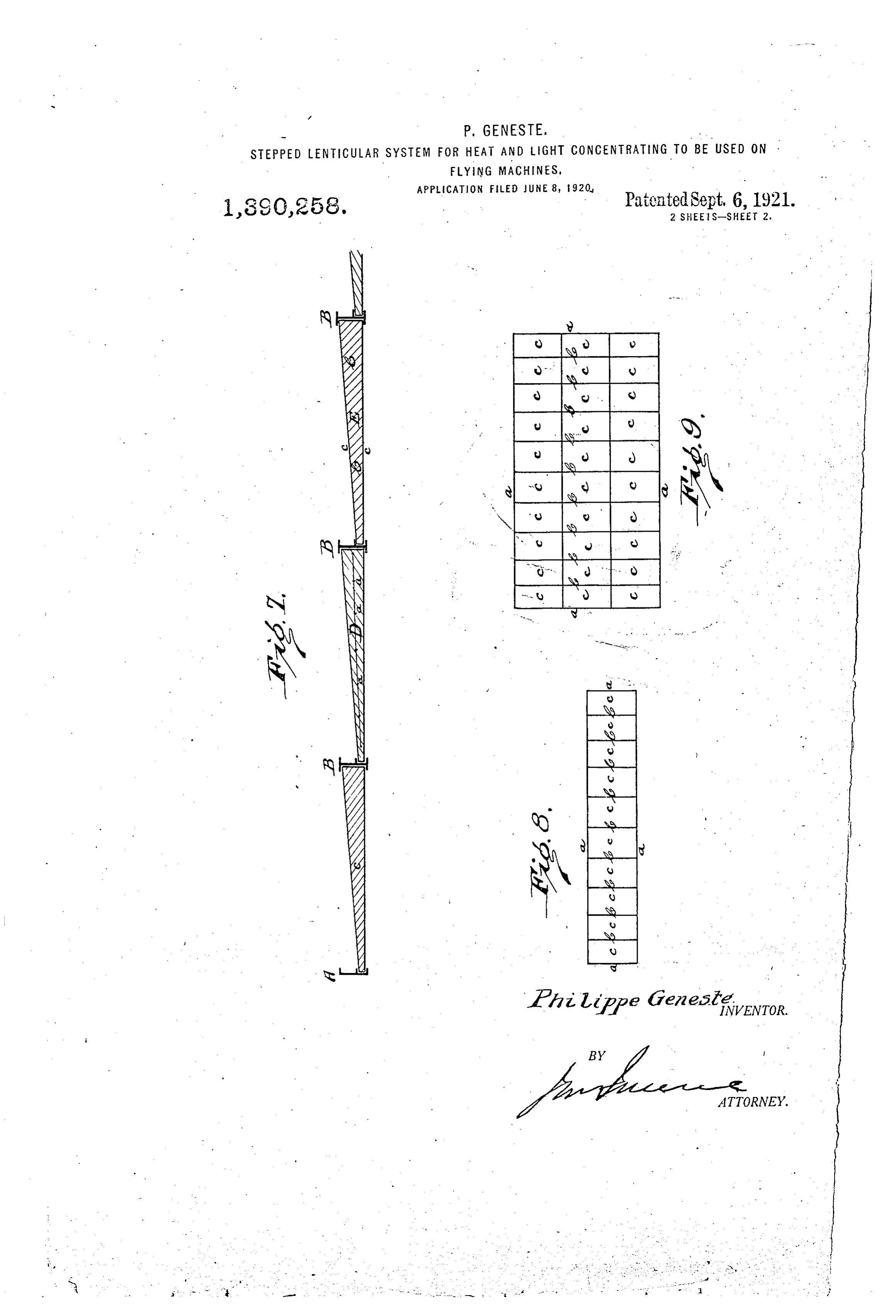
ammunition and the like enemy formations, Fig. 7 is an enlarged sectional view of a it may be understood that flying machines of portion of an aeroplane wing showing three 45 such kind are a valuable asset to the national lens elements inserted into the frame. 00 defense. Figs. 8 and 9 show diagrammatical views Furthermore flying machines provided of a plane with the invention applied. with such lens systems forming the planes, In the drawings, a designates the central may be used for heating the ground, hasten lens and l, b the steps or gradations of a len 50 ing the germination of seeds or the maturity ticular system of cylindrical shape in Figs. l05 of crops, melting snow, evaporate the Water 1 to 3 while in Fig. 4 a shows the central lens, of saltworks, and generally for heating and b, b the stepped annular concentrically dis. drying purposes. Of course in the last posed segments of a lenticular systern of named applications, the temperature should spherical shape.
55 not be very high. Finally, as light accumu A-B is the frame into which are inserted 0
Page 4
three lens elements, the first one being of the same on the frame of the planes. The solid glass as C, the second one of solid glass device may be applied to any kind of flying as D with reinforcing wire net d, while the machines and such features may be readily third one E being formed with an envelop constructed by the persons skilled in the art. 30 e containing a gaseous or liquid fluid f. Having now fully described my said in Of course the lenticular system may have vention, what I claim and desire to secure by various convergent forms, such as for in Letters Patent, is:
stance convexo convex, plane and convex and 1. The combination with a plane of a fly the like or various divergent forms, con ing machine, of a lenticular system having a O cavo-concave, plane and concave and the like. focus beyond the plane applied thereto for 35 The divergent formations are applied to forming a light and heat accumulator. gases having a coefficient of refraction lower 2. The combination with an exposed por than that of atmospheric air and the con tion of a flying machine, of a lens applied to vergent ones are used with solid bodies or such portion to concentrate the rays of en 40 5 liquids or with gases having a higher coeffi ergy at a point below the flying machine. cient of refraction than atmospheric air. 3. The combination with the wing of a fly Owing to the large dimensions of such ing machine, of a system of lens carried heat and light accumulators, high tempera thereby to concentrate the light and heat tures may be produced around the lenticular rays at a point below the flying machine. 20 focus so that the bundle of rays passing In testimony whereof I have hereunto set 45 above the troops of the enemy may instan my hand in presence of two witnesses. taneously disable a number of same. - PHILIPPE GENESTE. Inventor does not claim any features for . Witnesses:
covering the lenticular device when it is not FRANK. B. HALL, JR., 25 made use of it, nor any means for supporting JuIIAN KEMBLE SUEDBERG.
Provenance
- Collection
- Cited prior art
- Original PDF
- patentimages.storage.googleapis.com →
- Filed
- 1920-06-08
- Pages
- 4
- Method
- pdftotext (the PDF's own text layer) + pdftoppm 300dpi page scans
- Source
- Google Patents bibliographic record
- Granted
- 1921-09-06
- Inventors
- Geneste Philippe
- Transcribed from
- patentimages.storage.googleapis.com →