patent · US3964889
Continuous filter silo for the cleaning of flue gases
22 June 1976
Page 1 — bibliographic record
United States Patent (19) 11) 3,964,889 Lachnit [45] June 22, 1976 (54) CONTINUOUS FILTER SLO FOR THE 601,386 5/1948 United Kingdom. a -a - - - - - 55/474 CLEANING OF FLUEGASEs (75) Inventor: Friedrich
Germany Lachnit, Mulheim (Ruhr), Primary Examiner
Attorney, Bernard Nozick
Agent, or Firm-Law Firm of Roland T.
Brvan (73) Assignee: Deutsche Babcock & Wilcox ry
Aktiengesellschaft, Germany 57 ABSTRACT (22 Filed: Oct. 7, 1974 This invention relates to apparatus for charging and (21) Appl. No.: 512,975 emptying filter material in a continuous filter silo for the purification or cleaning of flue gases, and in one 30 Foreign Application Priority Data embodiment comprises a layer of filter material is lo Oct. 11, 1973 G 235 1003 cated between two substantially vertically arranged a Clany............................ wall sections which have apertures, and wherein the layer of filter material, defined by the wall sections 52 U.S. Cl....................................... 5:52, which are of annular cross section, is subdivided by at 51 Int. Cl. Bold 46/30 least 4 vertically arranged intermediate walls into seg (58) Field of search."5598.99.73,77390 ments, and wherein means are provided for the con 55/390 429,474,479 282. 231288 d 288 trolled feed of flue gases such that selectively two of E 288 d. 283.98fi26. 140 the segments at a time are excepted from the action of flue gas, thereby permitting the renewal of the filter 56) References Cited material, while the remaining segments being under full action of flue gas.
FOREIGN PATENTS OR APPLICATIONS
593,156 10/1947 United Kingdom................... 55/474 15 Claims, 4 Drawing Figures
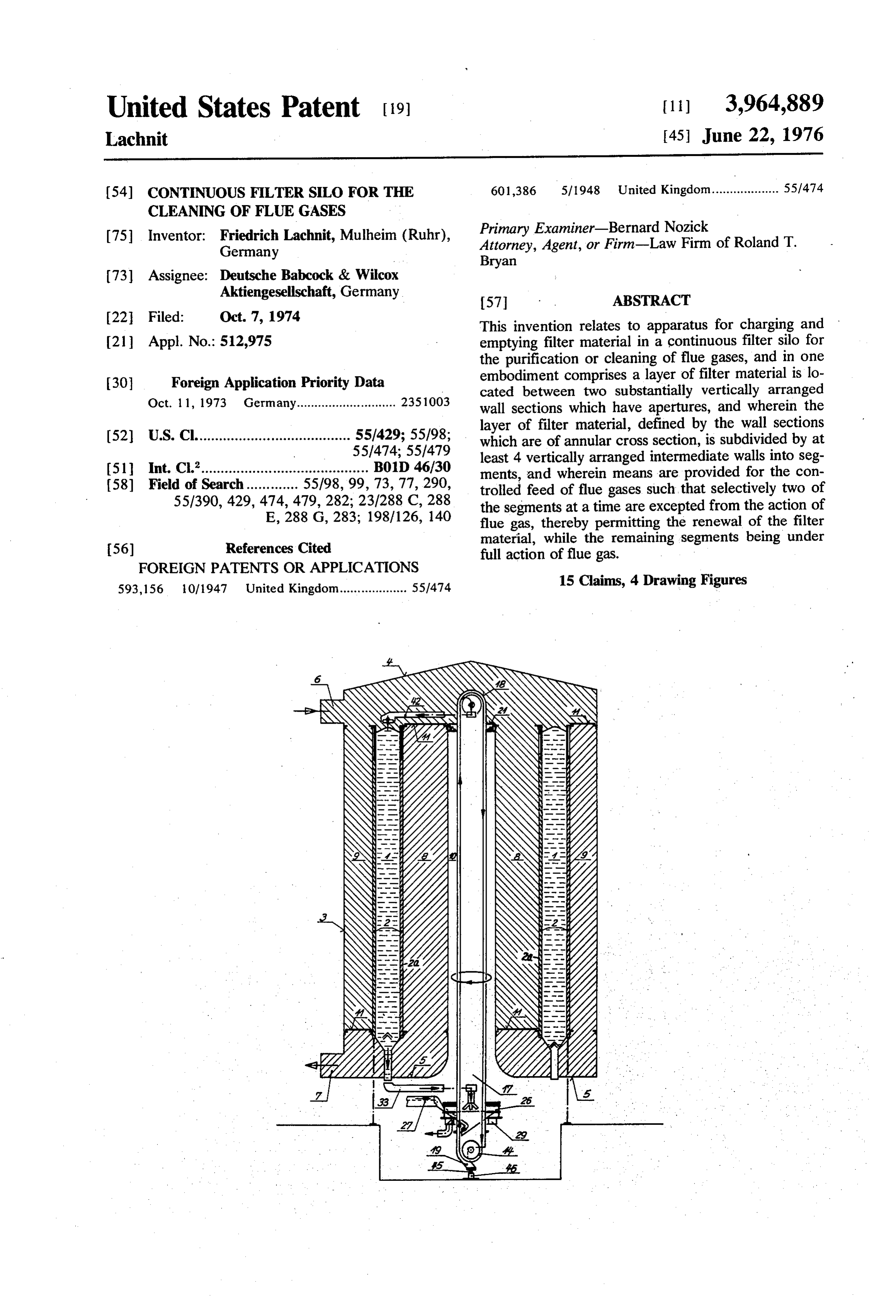
Page 2
Drawing sheet — no readable text.
Page 3
Drawing sheet — no readable text.
Page 4
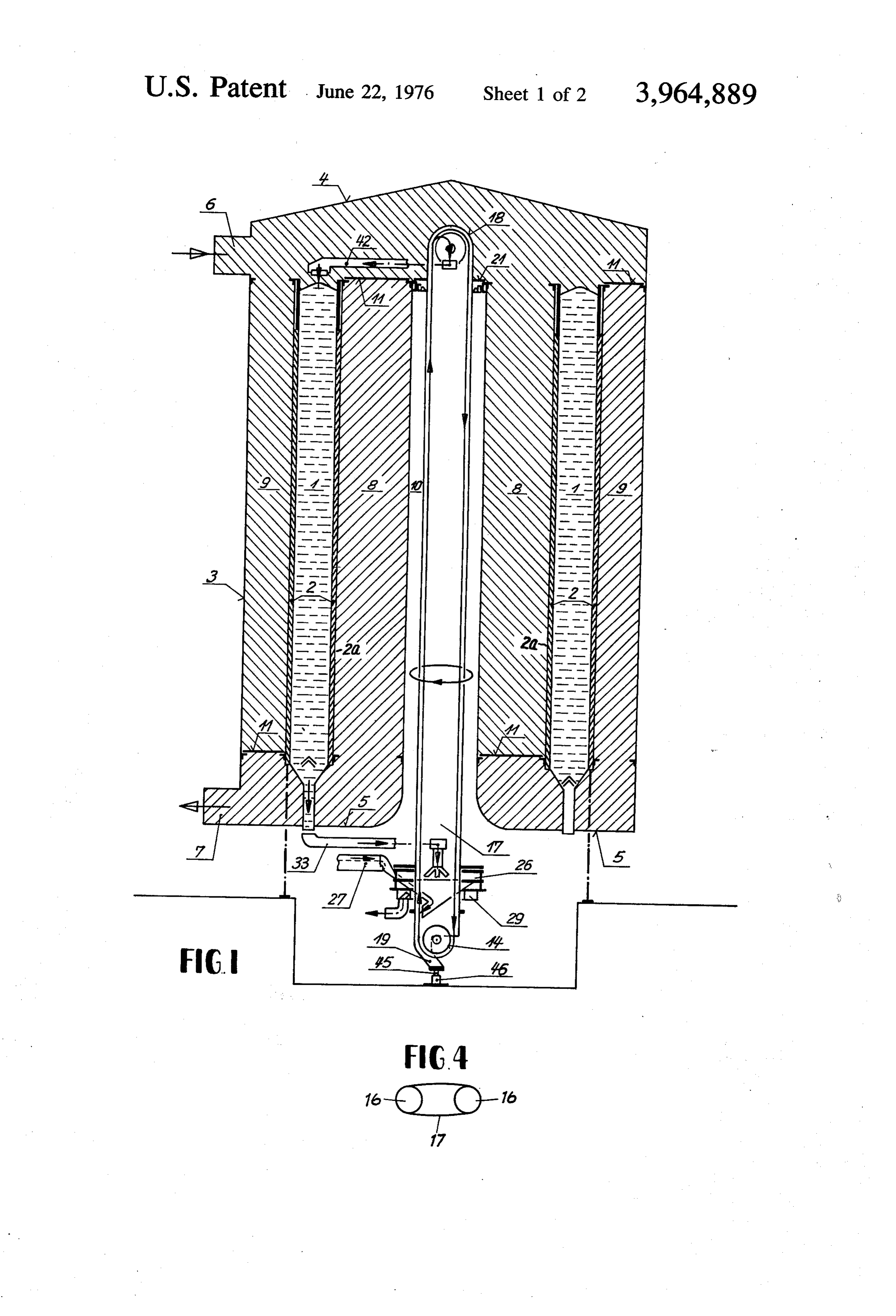
through which the charging and emptying system, de
CONTINUOUS FILTER SILO FOR THE CLEANING scribed in detail below, is positioned. OF FLUE GASES The filter layer 1 as well as the gas ducts 8 and 9 have BACKGROUND OF THE INVENTION been subdivided into a number of segments by means of wall sections (not shown) in radial-vertical direction.
So-called continuous filter silos are used for the de The charging of material into the segments will be sulfurization offlue gases by means of absorption of the stopped for such time as the segment in question is sulfur dioxide into activated coke granulate. During the exposed to flue gas. Usually, flue gas is periodically exposure of flue gas, the filter material layer is retained O stopped from flowing into two adjacent filter material in place. Such exposure of selected segments to flue gas segments of the filter silo at a time for the purpose of is temporarily interrupted in order to effect removal, as changing the filter charge. For this purpose, the corre well as replenishing, of the filter material in those seg sponding segments of the gas ducts 8 and 9, at their ments. In known perse devices, the filter material may upper and lower ends, are closed in groups by means of be fed through a feed line coming in over the roof of plates 11 which are rotatably mounted around the ver the silo. However, a continuous filter silo meant for a 15 tical longitudinal axis of the silo. Upon completion of 700 megawatt power station must process approxi the recharging and emptying process or cycle, the mately 4,000 tons of coke within 1 or 2 days. Typically, plates 11 will be advanced by one segment, and the a continuous filter silo of such a magnitude will be over cycle may then be repeated. The process of charging 30 meters high. Such height can render the filling and and emptying of a filter segment, with the described emptying of the individual segments of the filter mate 20 intermittent exposure of the filter segments, is apparent rial layer difficult, if not impossible. from the filter segment shown in FIG. 1 on the left Accordingly, it is an object of the present invention hand side.
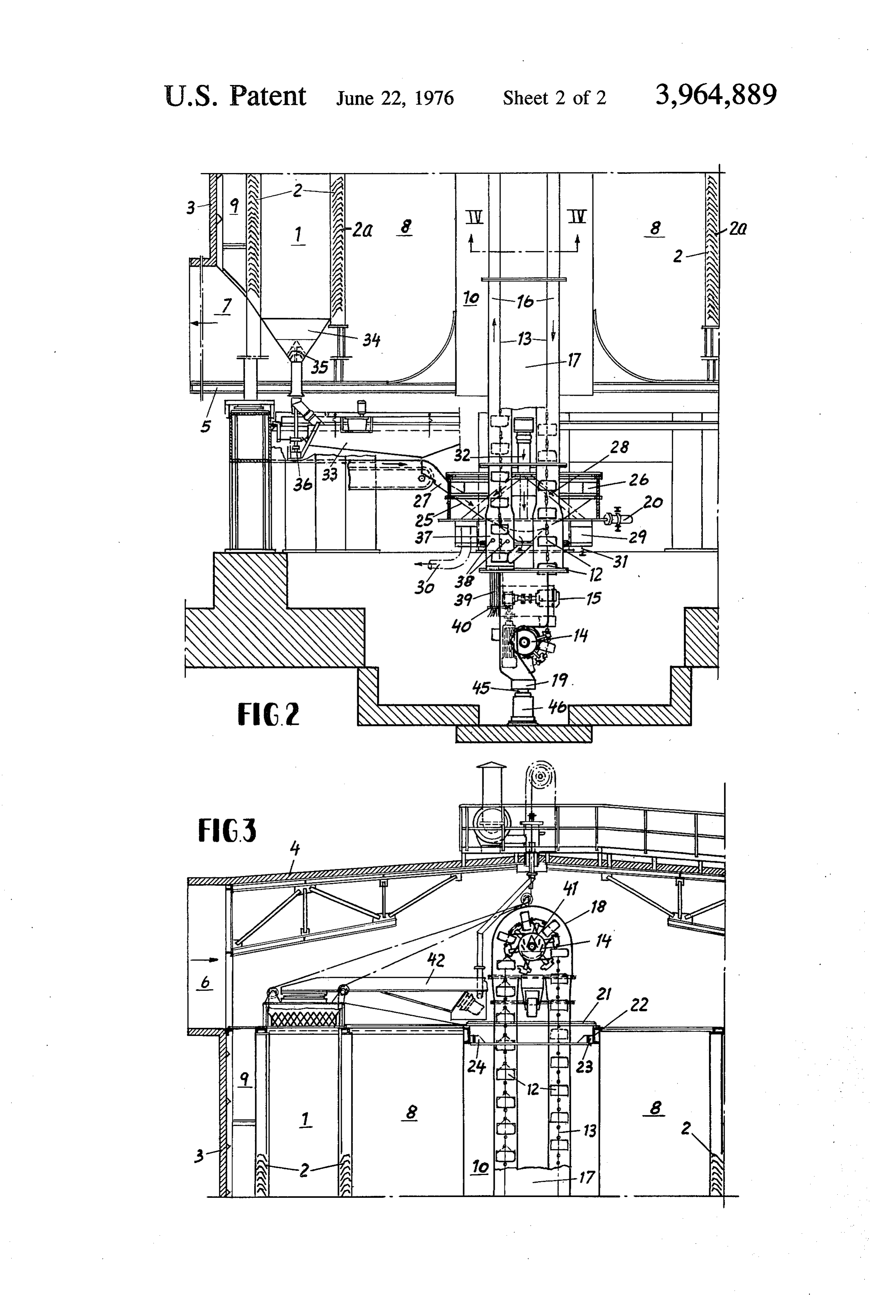
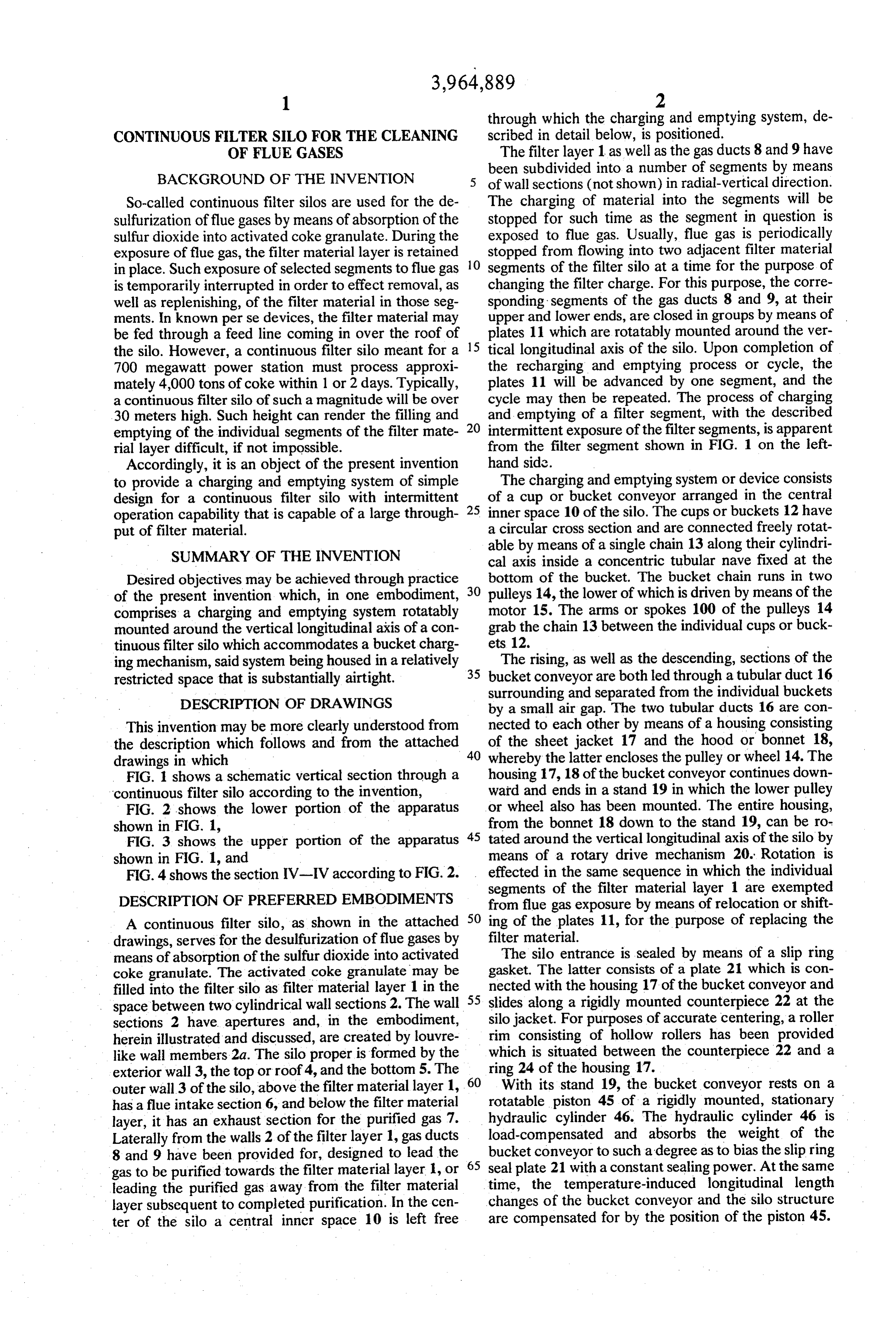
to provide a charging and emptying system of simple The charging and emptying system or device consists design for a continuous filter silo with intermittent 25 of a cup or bucket conveyor arranged in the central operation capability that is capable of a large through inner space 10 of the silo. The cups or buckets 12 have put of filter material. a circular cross section and are connected freely rotat able by means of a single chain 13 along their cylindri
SUMMARY OF THE INVENTION cal axis inside a concentric tubular nave fixed at the Desired objectives may be achieved through practice bottom of the bucket. The bucket chain runs in two of the present invention which, in one embodiment, 30 pulleys 14, the lower of which is driven by means of the comprises a charging and emptying system rotatably motor 15. The arms or spokes 100 of the pulleys 14 mounted around the vertical longitudinal axis of a con grab the chain 13 between the individual cups or buck tinuous filter silo which accommodates a bucket charg ets 12.
ing mechanism, said system being housed in a relatively 35 The rising, as well as the descending, sections of the restricted space that is substantially airtight. bucket conveyor are both led through a tubular duct 16
DESCRIPTION OF DRAWINGS
surrounding and separated from the individual buckets by a small air gap. The two tubular ducts 16 are con
This invention may be more clearly understood from nected to each other by means of a housing consisting the description which follows and from the attached 40 of the sheet jacket 17 and the hood or bonnet 18, drawings in which whereby the latter encloses the pulley or wheel 14. The FIG. 1 shows a schematic vertical section through a housing 17, 18 of the bucket conveyor continues down continuous filter silo according to the invention, ward and ends in a stand 19 in which the lower pulley FIG. 2 shows the lower portion of the apparatus or wheel also has been mounted. The entire housing, shown in FIG. 1, from the bonnet 18 down to the stand 19, can be ro FIG. 3 shows the upper portion of the apparatus 45 tated around the vertical longitudinal axis of the silo by shown in FIG. 1, and means of a rotary drive mechanism 20. Rotation is FIG. 4 shows the section IV-IV according to FIG. 2. effected in the same sequence in which the individual segments of the filter material layer 1 are exempted
DESCRIPTION OF PREFERRED EMBODIMENTS from flue gas exposure by means of relocation or shift A continuous filter silo, as shown in the attached 50 ing of the plates 11, for the purpose of replacing the drawings, serves for the desulfurization offlue gases by filter material.
means of absorption of the sulfur dioxide into activated The silo entrance is sealed by means of a slip ring coke granulate. The activated coke granulate may be gasket. The latter consists of a plate 21 which is con filled into the filter silo as filter material layer 1 in the nected with the housing 17 of the bucket conveyor and space between two cylindrical wall sections 2. The wall 55 slides along a rigidly mounted counterpiece 22 at the sections 2 have apertures and, in the embodiment, silo jacket. For purposes of accurate centering, a roller herein illustrated and discussed, are created by louvre rim consisting of hollow rollers has been provided like wall members 2a. The silo proper is formed by the which is situated between the counterpiece 22 and a exterior wall 3, the top or roof 4, and the bottom 5. The 60 ring 24 of the housing 17.
outer wall 3 of the silo, above the filter material layer 1, With its stand 19, the bucket conveyor rests on a has a flue intake section 6, and below the filter material rotatable piston 45 of a rigidly mounted, stationary layer, it has an exhaust section for the purified gas 7. hydraulic cylinder 46. The hydraulic cylinder 46 is Laterally from the walls 2 of the filter layer 1, gas ducts load-compensated and absorbs the weight of the 8 and 9 have been provided for, designed to lead the bucket conveyor to such a degree as to bias the slip ring gas to be purified towards the filter material layer , or 65 seal plate 21 with a constant sealing power. At the same leading the purified gas away from the filter material time, the temperature-induced longitudinal length layer subsequent to completed purification. In the cen changes of the bucket conveyor and the silo structure ter of the silo a central inner space 10 is left free are compensated for by the position of the piston 45.
Page 5
The lower part of the housing has been designed as a longitudinal axis of the silo, whereby such system has a filter material distribution device which consists of a rotatory drive operating in the sequence of the renewal cone 25, the orifice of which terminates above a filler or replacement of the filter material in the segments. Sector 37, hereinafter described in greater detail. The Such a device can be housed in a relatively restricted cone 25 is hermetically connected to a rigidly mounted space and still feature a very high throughput. It is well annular frame 26, having a connection 27 for the in suited for the continuous charging and emptying of the coming regenerated filter material. individual filter material segments of the silo. The de Four chutes 28 are led through the cone, all of them vice according to the invention can also be used in the terminating in a narrow, rigid annular channel 29 same manner, without changing the basic equipment, which is formed by another annular frame and is under 10 even if the silo later on is expanded, by arranging a biasing pressure provided by springs 31. Through an second filter material layer or stratum which surrounds exhaust pipe 30 arranged at the annular channel 29, the the aforementioned layer of filter material. filter material is removed by suction and transported lock-type The charging or filling unit will expediently contain into a desorber. That the chutes 28 are four in number airtight feeding compartments or elements ensures that the suction pipe sections in the annular 15 consisting of buckets having a circular cross section channel 29 are kept short. The chute pipes all originate and being connected along their cylindrical axes by from a central pipe 32. The charged filter material 1 means of one single chain, and whereby their exterior from the corresponding segment is transported towards wall slides in a tubular duct with a small air gap, i.e. in the central pipe 32 over a vibration conveyor which is 20 a relatively airtight manner. Thereby the rotatable tub amplitude-modulated so as to monitor the size of the ular ducts are connected with a housing, and the latter charge increments. The discharge channel is firmly is connected with the silo entrance via a slip ring seal. mounted to the rotatable housing and is moved under The sealing effect achieved in the above manner is neath the orifice 34 of the filter material layer which sufficient for the effective separation of the silo's atmo has a closure. The closure 35 of the discharge orifice 34 sphere from the atmosphere outside. This tends to keep is pressed upward from below by means of a rod 36 25 the expenditure for the construction of the silo low, whenever the discharge channel 33 has been moved in because the use of an expensive bucket wheel lock can position. The arrows show the direction of motion of be dispensed with and the flue gas feed mechanism into the regenerated, as well as the charged, filter material. the silo head can be kept much simpler. The charging section 37 for the buckets 12, in the According to an additional characteristic of the in described charging system, is in vertical position. It has 30 vention, the arrangement of a vertically oriented been provided for in the lower part of the tubular duct bucket charging mechanism permits simplification of 16. During upward movement, the individual buckets the structure as well as the handling of large amounts of pass through the charging system and are filled in the filter material, since the length of such charging mecha process. Above the charging section 37 there is a rim of 35 nism or section only needs to be not less than the dis nozzles 38 obliquely directed against the filling surface tance between two buckets. In this arrangement, the in the buckets 12. The jets of air emanating from the underside of the charging mechanism or section is jets 38 blow away the excess filter material heaped sealed off by means of a jacket of sectional rods closely above the rim of the bucket. The nozzle axes are in and resiliently hugging the outer bucket wall. The almost horizontal position and arranged as a group of 40 abovementioned jacket, moreover, possesses a degree secants relative to the bucket circle, whereby their of total mobility in a radial direction which permits the direction of blowing has been adjusted in a dextrorota equalization and damping of vibrations of the chain tory or sinistrorotatory direction as a group. axis resulting from the polygonally designed arms of the The length of the charging section 37 corresponds at lower reversing wheel. In the arrangement of the verti least to the distance between a pair of buckets. The 45 cal charging or filling system or section traversed by the region beneath the charging section is sealed by means buckets, it is advantageous to provide, above and inside of a jacket of sectional radially extended rectangular the tubular duct, a rim of nozzles having jets directed rods 39. The sectional rods 39 hug the outer bucket against the heaped material in the buckets. The air jets wall tightly and resiliently and thus provide efficient emanating from the nozzles blows away the material sealing. The tight fit of the sectional rods 39 is effected 50 heaped above the upper rim of the buckets so that they by two loops of ropes provided with springs. Further will just be filled to the brim. This prevents the material more, the sectional rods 39, on their exterior, have from falling out of the buckets during conveying and radial slots, each of which is engaged above and below getting caught in the narrow air gap between the outer by a retaining ring for the purpose of axial stability. bucket walls and the tubular duct. The charged buckets which are moved upwards A filter material distributor can be employed to ad through the tubular duct 16 are discharged above the 55 vantage in this arrangement. According to another upper pulley 14. As a protection against filter material advantageous characteristic of the invention, it is sug dropping down, the pulley 14, as well as its shaft, is gested to provide, for the lower part of the housing covered on both sides by roof-shaped baffles 41, de - connecting to two tubular ducts, a filter material distri signed to direct the filter material towards both sides of 60 bution device for two streams of material crossing each the shaft, and into a driven conveyor channel 42. The other's paths, consisting of a cone which is sealed and conveyor channel 42 is connected with the hood or is connected to a rigidly mounted annular frame that is bonnet 18 and is synchronously driven together with provided with a connecting piece for one stream, plus a the elevator axle across each individual segment of the second part consisting of four chutes being led through filter material layer 1. the cone and terminating in a rigidly mounted, spring From the foregoing description, it will be clear that 65 biased annular channel equipped with an exhaust pipe through practice of this invention it is possible to pro or tube. This helps to simplify the replacement of filter vide in the central interior of the silo, a charging and material by using the identical device for the charging emptying system rotatably mounted around the vertical as well as for the emptying, whereby such device is
Page 6
capable of being connected to the corresponding seg 6. Apparatus according to claim 5, in which, in the ments. Such device can be introduced into the filter lower vertical section of the charging system, a charg cycle consisting of absorption and desorption. ing section has been provided for the buckets, and It is to be understood that the embodiments herein wherein the length of such section is at least as great as described and shown are by way of illustration and not the space between adjacent buckets. of limitation, and thus other embodiment may be made 7. Apparatus according to claim 6, in which the un by those skilled in the acts without departing from the derside of the charging section is sealed by means of a spirit or scope of this invention. jacket of sectional rods, such jacket being impervious I claim: to the granular material being conveyed, and wherein 1. In a continuous filter silo for the purification of 10 said sectional rods hug the buckets tightly and resil flue gases by means of a filter layer located between iently.
two substantially vertically arranged wall sections of 8. Apparatus according to claim 7, in which the sec circular cross-section that are provided with apertures, tional rods are biased or pressed against the outer wall wherein the filter material layer containers defined by 15 of the buckets via at least one rope loop. said wall sections are subdivided into segments by 9. Apparatus according to claim 8, in which on the means of at least four vertically arranged intermediate outer part of the sectional rods, radial slots have been wall sections, and wherein means are provided for the provided which are engaged by one or two retaining controlled intake of flue gas in such a way that selected of said segments have have their exposure to flue gas 20 rings for the purpose of axial stability. 10. Apparatus according to claim 9, in which the stopped for the purpose of regeneration of the filter jacket consisting of the sectional rods permits a total material the improvement comprising, a charging and emptying system positioned in the central inner space radial 11.
mobility.
Apparatus according to claim 10, in which a
short of the silo, which system is rotatably mounted around distance above the charging section, a rim of nozzles the vertical longitudinal axis of the silo and comprises a has been arranged in the widened lower part of the bucket-type elevator means adapted for transporting 25 tubular duct, whereby the axes of the individual nozzles filter material from the region of the bottom of said silo have been set in the pattern of a group of secants in to the region of the top of said silo and for discharging relation to the bucket rim, and adjusted with a common the contents of the bucket of said elevator onto means for transporting said material into selected of said seg 30 rotatory
direction of blow.
Apparatus according to claim 11, in which the ments of said filter material container, and drive means contents of each bucket for causing said transporting means to move to selected of the upper pulley, andare emptied towards both sides wherein the shaft of said pull
2. Apparatus according to claim 1, in which the over ley, on both sides, is protected by a roof-shaped baffle charging system has charging buckets sealed in the 35 channel. which the buckets are emptied into a conveyor manner of a lock multi cell sluice.
3. Apparatus according to claim 1, in which the ele 13. Apparatus according to claim 12, in which the ments of the charging system include buckets of circu lower been part of a housing connecting tubular ducts has provided with a filter material distributor for two lar cross section connected to each other along their cylindrical axes by means of a chain, which is posi 40 streams of materials with their paths crossing, wherein tioned inside a tubular chamber, the bottom of the such distributor, for one stream, consists of a cone buckets being fixed at their bottom to said chain, and connected and sealed to a rigidly mounted annular wherein the outer wall of said buckets is guided in a frame with a connecting piece, and a second part, con tubular duct and is separated therefrom by a small air sisting of four chute pipes leading through the cone, gap. and wherein said pipes terminate in a firmly mounted, 4. Apparatus according to claim 3, in which the rotat resiliently biased annular channel provided with an
able tubular ducts are connected to a housing which is exhaust pipe.
connected to the silo entrance via a slip ring seal. 14. Apparatus according to claim 13, in which the 5. Apparatus according to claim 4, comprising a slip rotary drive for the rotation of the housing acts on the ring seal biased with a constant sealing pressure result filter material distributor on the outside of the silo. ing from a part of weight of the charging and emptying 50 15. Apparatus according to claim 14, comprising system, and a load-compensated hydraulic cylinder for conveyor chute rotatable synchronously with the eleva automatic compensation for temperature induced elon tor for the removal of filter material from segments. gation and the absorption of the load.
Provenance
- Collection
- Cited prior art
- Original PDF
- patentimages.storage.googleapis.com →
- Filed
- 1974-10-07
- Pages
- 6
- Method
- pdftotext (the PDF's own text layer) + pdftoppm 300dpi page scans
- Source
- Google Patents bibliographic record
- Granted
- 1976-06-22
- Inventors
- Friedrich Lachnit; Deutsche Babcock and Wilcox AG
- Transcribed from
- patentimages.storage.googleapis.com →