patent · US3302042
Nuclear reactor with thermionic converter
31 January 1967
Page 1
Drawing sheet — no readable text.
Page 2
Drawing sheet — no readable text.
Page 3
United States Patent Office Patented Jan. 31, 1967
The present invention utilizes heat pipes in a nuclear
NUCLEAR REACTOR WITH THERMONIC reactor as the heat transferring elements. According to CONVERTER the invention, nuclear core components, especially the George M. Grover, Los Alamos, N. Mex, and Claus A. fuel elements, involved in fission, moderation, and reflec Busse, Laveno, and Josef Bohdansky, Taino, Italy, as tion are thermally coupled to heat pipes. The non signors, by direct and mesne assignments, to the United coupled portions of the pipes extend outward from the States of America as represented by the United States reactor core to constitute thermal sinks. The condenser Atomic Energy Commission region of the heat pipe terminates in an emitter electrode Filed Oct. 23, 1965, Ser. No. 504,270 of a thermionic converter. Furthermore, the front face 4 Claims. (C. 310-4) 10 of the heat pipe can directly constitute the emitter elec This invention relates to a nuclear reactor and, more trode in a thermionic converter. If desired, the front particularly, to a reactor for the direct conversion of heat face can be vapor-plated with a special electron emissive to electricity. layer. Finally, the collector electrode of the thermionic In nuclear reactors heretofore constructed, the extrac converter can be coupled to a heat pipe for the removal tion of heat produced by nuclear fission requires in gen 5 of heat generated in the collector.
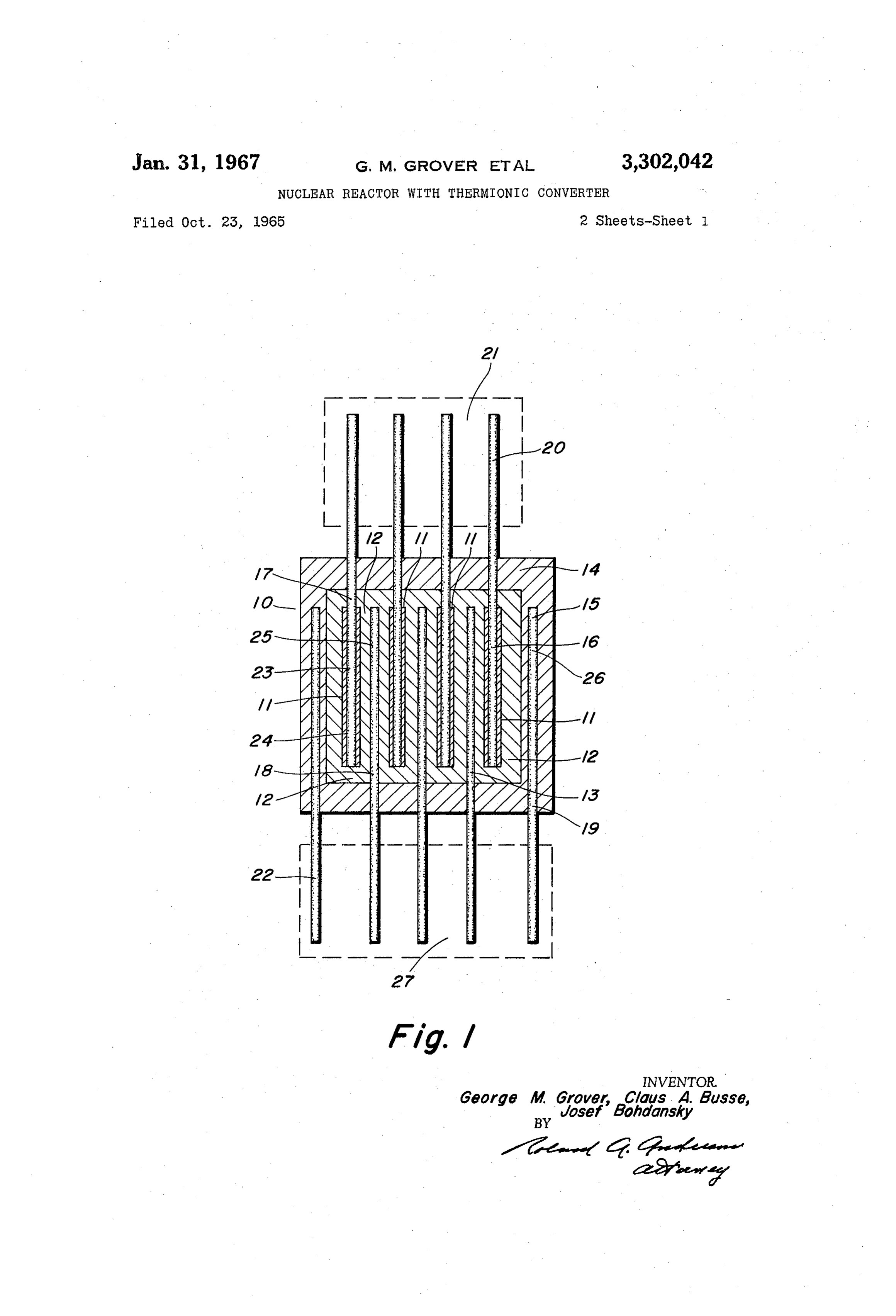
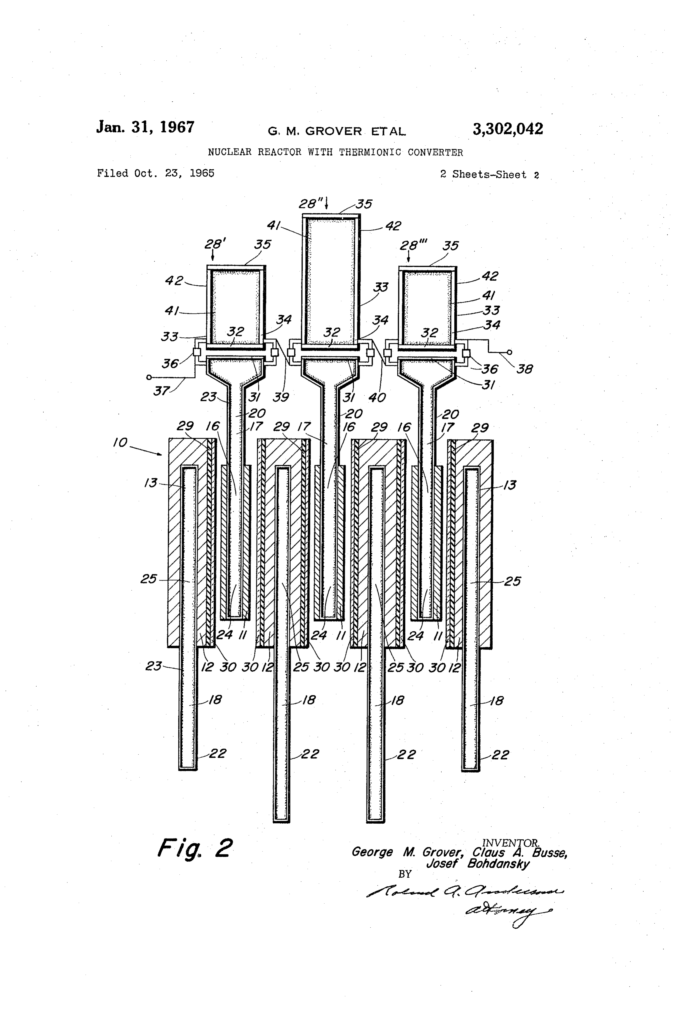
eral the circulation of a heat extracting medium between Various other objects and advantages will appear from the heat generating zone and an external heat cooling the description of the following embodiment of the inven device, dissipating or transforming heat into power, and tion, and the novel features will be pointed out therein reintroducing the cooled-down medium into the heat after in connection with the claims. generating zone. For this purpose, an often rather com 20 The invention will be clearly understood by reference plicated system of cooling channels passes through the to the accompanying two sheets of drawings wherein: reactor which is connected externally to a corresponding FIG. 1 is a vertical sectional view of a moderated nu circulating system. Furthermore pumps and other com clear reactor equipped with heat pipes. ponents for the circulation and control of the media in 25 FIG. 2 is a vertical sectional view of a moderated nu the cooling channels are required. clear reactor with thermionic converters equipped with With the invention of the "heat pipe' an entirely new heat pipes.
technique of heat transfer has come to life, see Grover, In the illustrated embodiment of the invention as seen Cotter and Erickson, Structures of Very High Thermal in FIG. 1, a heterogeneous nuclear reactor 10 is provided Conductance, 35 Journal of Applied Physics 1990 (June 30 with fissile fuel 11 having a passageway 16, moderator 12 having a passageway 13 extending partially therethrough, 1964), and application Serial Number 327,559 filed De cember 2, 1963 by George M. Grover, now Patent and reflector 14 having a passageway 15 extending par 3,229,759, dated March 29, 1966. A "heat pipe” is a tially therethrough.
transfer device comprising a container, condensable vapor, Disposed in passageway 16 of fissile fuel 11, passage and capillary means disposed within the container capable 35 way 13 of moderator 12, passageway 15 of reflector 14 of causing the transport of the condensed vapor from a and thermally coupled thereto are fissile fuel heat pipe cooler area of the container to a hotter area. The trans 17 having an evaporator region 24, moderator heat pipe port of the vapor through the container uses, as the driving 19 18 having evaporator region 25, and reflector heat pipe force, the difference in vapor pressures in the high tem having an evaporator region 26 respectively. The non perature zone and the cold temperature zone. The liquid 40 coupled portion 20 defining a condenser region for heat which condenses in the cold Zone is returned to the evap pipe 17 extends outwardly from the nuclear reactor 10 to oration zone by capillary action. Thus, fluid circulation is constitute a heat sink 21. The non-coupled portion 22 established in the pipe with the non-heated end of the pipe defines a condenser region for heat pipes 18 and 19 and acting as a condenser. By means of this circulation, a constitutes heat sink 27.
heat flux is created to flow from the heated end of the 45 The inner walls of heat pipes 17, 18, and 19 are covered pipe to the pipe's non-heated end. The temperature drop with a wick 23 of suitable capillary structure. Only the along the heat pipe is powers of ten lower than in the wick 23 disposed within fissile heat pipe 17 is numbered case of conventional heat transports. Therefore, an es in FIG. 1. It is a requirement that the pore size be suf sentially uniform temperature distribution is established ficiently small to produce capillary action and that the along the entire pipe surface. material utilized be compatible at the condition of opera 50 tion. The tubular fissile fuel 11 may be separately
Accordingly, it is an object of the present invention to mounted on heat pipe 17 or the fissile fuel may be lined provide a nuclear reactor which directly converts the directly on the outer surface of the heat pipe. As a fis heat produced by fission to electricity. sile fuel, a Mo-UO cermet may be employed. Fissile It is another object to provide a nuclear reactor wherein fuel heat pipe 17 may be formed from tantalum. Fissile all the waste heat is dissipated solely by the heat transfer fuel heat pipe 17 contains silver as a heat carrier fluid and mechanism of radiation. operates at a temperature of about 1800° C. Moderator It is another object to provide a nuclear reactor useful heat pipe 18 and reflector heat pipe 19 may be formed of as a power source in space. niobium and contain cesium as the heat carrier fluid. It is another object to provide a nuclear reactor wherein 60 In FIG. 1 means for controlling the reactor along with no separate coolant is necessary or pumps necessary to the biological and thermal shielding have been omitted. circulate the coolant. Such means are well within the scope of one skilled in the It is another object to provide a nuclear reactor which subject art. If the moderator is to be maintained at a directly converts the heat produced by fission to elec temperature cooler than the fuel temperature, thermal tricity under gravity free conditions. 65 shields must be inserted at least between these two conn
It is another object to provide a thermionic converter ponents.
which is removed from the immediate radiation field of The lilustrated embodiment of the invention, as shown a nuclear reactor which constitutes the heat source for in FIG. 2, is an adaptation of the reactor 10 shown in the thermionic converter. FIG. 1 and is employed to heat thermionic converters 28, It is a further object to provide a nuclear reactor for 70 28' and 28' in a vacuum environment. In FIG. 2, a space vehicles for the direct conversion of nuclear energy heterogeneous nuclear reactor 10 is shown comprised of into electrical energy. a fissile fuel 11 having a passageway 16, and moderator
Page 4
12 having a passageway 13 extending partially there 24, the evaporation of liquid from the pores of the wick through. The reflector 14 of FIG. 1 is not shown in FIG. causes a reduction of the radius of curvature of the liquid 2, although a reflector may be disposed about the mod Surface, as the liquid is evaporated from the pores, to a erator 12 as is shown in FIG. 1. limit of the radius of curvature of the pores in the wick. Disposed in passageway 16 of fissile fuel E1, passage As described in the reference on "heat pipes' by Grover, way 13 of moderator 12, and thermally coupled thereto Cotter and Erickson, the pressure in the liquid is reduced are fissile fuel heat pipe 17 having an evaporator region in proportion to the radius of curvature of the liquid 24 and moderator heat pipe 18 having evaporator region surface. Therefore, the pressure in the liquid is reduced 25 respectively. The non-coupled portions 20 defining a proportionately more in the evaporator section of the condenser region for heat pipe 7 extend outwardly from 10 wick than in the condenser section of the wick. The pres the nuclear reactor 10. The non-coupled portion 22, Sure differential drives the liquid through the wick 23 external to reactor 10, defining a condenser region for from the condenser region 20 to the evaporator region 24 heat pipe 18 defines a heat sink region. against the various retarding forces. The inner walls of heat pipes 17 and 18 are covered Emitter electrode 31 heated by heat pipe 17 emits elec with a wick 23 of suitable capillary structure. Only wick 15 trons which flow from emitters 31 to collectors 32. In 23 disposed within one of the fissile heat pipe 17 and Sulators 36 maintain the spacing between and provide moderator pipe 8 is numbered in FIG. 2. It is a re electric isolation between emitters 31 and collectors 32 quirement that the pore size be sufficiently small to pro The electromotive force generated between emitter elec duce capillary action and that the material utilized be trode 31 and the collector electrode 32 is taken off by compatible at the condition of operation. The moderator 20 means of electrical conductors 37 and 38 to a load (not 12 formed of zirconium hydride is separated from fissile shown). The electron flow from the emitter to the co fuel 11 by means of electrical insulation 29 and thermal lector is primarily dependent upon the absolute tempera shields 30. ture of the emitter and secondarily, on the thermal gradi The non-coupled portion 20 defining a condenser re ent between the hot emitter and the "cold' collector. By gion of heat pipe 17 which extends beyond reactor 10 25 employing silver as the carrier medium in heat pipe 17, carries electron emitter electrode 3. Secured to heat the emitter electrode 3 operates at a temperature of pipe 17 is electrical insulator 36. Carried by electrical about 1800° C.
insulator 36 is collector electrode 32. Collector heat in order to provide a substantial temperature dif pipe 33 wherein the region nearest the collector defines ferential between the hot emitter and the cold collector an evaporator region 34 is in turn carried by collector 30 as all thermionic converters require, the heat generated electrode 32. Collector heat pipe 33 is provided with by the electrons from emitter 31 innpinging on collector end closure member 35 so as to define a condenser region 32 must be removed from collector 32. Thus the heat 42. The inner walls of heat pipe 33 are covered with a generated liquifies the lithium so as to saturate wick 41 wick 41 of suitable capillary structure. within heat pipe 33. In the steady state heated condition, In FIG. 2, three thermionic converters 28, 28, 28' 35 the liquid temperature in the evaporator region 34 of are illustrated. The collector electrode of converter heat pipe 33 is slightly higher than the condenser region 28' is electrically connected to the emitter electrode of 42. The heat generated further vaporizes the liquid converter 28' by electrical connection 39. Likewise, the lithium in evaporator region 34. Due to the difference in collector electrode of converter 28' is electrically con 40 liquid temperature between evaporator region 34 and con nected to the emitter electrode of converter 28 by electri denser region 42, the resulting difference in pressure drives cal connector 40. Emitter electrode 31 of converter 23' the lithium vapor from the evaporator region 34 to con and collector electrode 32 of converter 28’ are provided denser region 42. The vapor upon reaching condenser re With electrical conductors 37 and 38 respectively. gion 42 transfers heat to a heat sink (not shown). A suit By disposing the thermionic converter 28 outside the able heat sink is apparent to those skilled in the art which reactor 0, the thermionic converter is withdrawn from 45 may be in the form of a heat exchanger or in the case the immediate radiation field of the reactor. of dissipating heat in space, the free end of collector Heat pipe E7 is preferably formed of tantalum and heat pipe 33 acts directly as a radiator. Upon transfer contains silver as the carrier medium. Moderator heat of heat to a heat sink, the vapor condenses to a liquid pipe 18 is preferably formed of niobium and contains at Condenser region 42 and thus creates a pressure dif cesium as the carrier medium. Collector heat pipe 33 50 ferential with respect to the evaporator region 34. The is preferably formed of niobium-zirconium, Nb-1 Zr and pressure differential drives the liquid through wick 41 contains lithium as the carrier medium. from condenser region 42 to evaporator region 34 against As in the case of F.G. 1, the control elements of the the various retarding forces. Thus, the collector 32 oper Ireactor and other structural components are not shown. ates at a temperature of about 1000 C. Such elements and structural components are well known 55 In that thermionic converters require a substantial tem to those skilled in the nuclear reactor art. perature differential between the hot emitter and the cold In operation, heat from fission in reactor 10 is applied collector, it is seen that the remarkable heat transfer to evaporator region 24 of heat pipe 7 which is thermal rate, with very Small temperature gradient associated with ly coupled to fissile fuel 11. After the heat is applied, the the heat pipe permits the efficient operation of this de Silver within heat pipe 7 becomes liquified and saturates 60 W1Ce.
Wicks 23. In liquified steady state heated conditions, the Likewise, heat pipes 8 and 19 shown in FIG. 1 are par liquid temperature in evaporator region 24 is slightly tially inserted in the moderator and reflector of reactor 10 higher than the non-coupled condenser region 20 of heat to extract heat generated in them in a manner set forth as pipe 17. The liquified silver in evaporator region 24 above. With the utilization of cesium as a carrier medium Vaporizes under the application of the heat from fission 65 for heat pipes 18 and 19 an operating temperature of 500 C. is achieved.
in reactor 10. Due to the difference in liquid temperature Due to the physical properties of the heat pipe, heat between evaporator region 24 and the condenser region 20 of heat pipe 17, the resulting difference in pressure in extraction drop.
takes place with extremely small temperature
Especially it eliminates conventional coolant cir
Vapor drives the vapor from evaporator region 24 to con 70 culation System, which is complicated, power consum denser region 20. The vapor arrives at condenser region ing, and neutron absorbing. For utilization of the reactor 20 wherein emitter electrode 31 acts as a heat sink so On earth, the reactor is preferably operated with the heat as to condensate the vapor to a liquid, filling the pores pipes horizontally mounted. If the free portions of the of the wick 23 and increasing the radius of curvature of heat pipes are curved upwards, the reflux of the con the liquid Surface in the wick. In the evaporator section 75 densate is aided by gravity. As may be seen from the
Page 5
figures, the heat pipes above and below the reactor 10 a third heat pipe having one end interior to the reactor have different lengths. By this means, first a spatial con core and thermally coupled to the moderator and figuration is achieved, which is particularly advantageous heated thereby the other end being exterior to the for incorporation of the invention in rockets. Second, reactor core for heat rejection by radiation; favorable conditions for heat radiation are achieved. 5 a condensible vapor disposed within each of said first Third, the parallel arrangement of the heat pipes accom second and third heat pipes; modates test runs of the reactor under conditions of capillary means covering the entire inner surfaces of gravity as already pointed out above. said first, second and third heat pipes for causing the It will be understood that various changes in the de transport of said condensible vapor within each re tails, such as vapor-plating the emitter electrode 31 with 0 spective heat pipe from the pipe's unheated end to its an electron emitting layer, or introducing cesium between heated end whereby heat is extracted from the re the emitter and collector electrode, or utilizing the front actor.
face of heat pipe 17 directly as the emitting electrode; 2. A heat extraction system according to claim 1 where Steps and arrangement of parts, which have herein been in the condensible vapor is silver. described and illustrated in order to explain the nature 5 3. A heat extraction system according to claim where of the invention may be made by those skilled in the art in the condensible vapor in the second heat pipe is within the principle and scope of the invention as ex lithium.
pressed in the appended claims. 4. A heat extraction system according to claim 1 where What is claimed is: in there is a plurality of first, second and third heat pipes 1. In a nuclear reactor core having fissile fuel and a 20 each lined with capillary means and each having therein moderator, a heat extraction system comprising: a condensible vapor; and, there is a plurality of collector a first heat pipe having one end interior to the reactor and emitter electrodes corresponding to the number of first core and thermally coupled to the fissile fuel and and second heat pipes.
being heated thereby, the other end being exterior to
a nemitter electrode thermally coupled to the end of References Cited by the Examiner said first heat pipe which is exterior to the core; UNITED STATES PATENTS a collector electrode electrically isolated from said 3,229,759 1/1964 Grover ----------- 62-487 X emitter electrode and disposed so as to collect elec 3,243,613 3/1966 Grover ----------- 176-39 X trons emitted from said emitter electrode; FOREIGN PATENTS a second heat pipe, one end of which is thermally cou pled to said collector electrode and heated thereby 1,147,218 6/1957 France.
and the other end of which is disposed for heat re jection by radiation; REUBEN EPSTEIN, Primary Examiner.
Provenance
- Collection
- Cited prior art
- Original PDF
- patentimages.storage.googleapis.com →
- Filed
- 1965-10-23
- Pages
- 5
- Method
- pdftotext (the PDF's own text layer) + pdftoppm 300dpi page scans
- Source
- Google Patents bibliographic record
- Granted
- 1967-01-31
- Inventors
- George M Grover; Claus A Busse; Bohdansky Josef
- Transcribed from
- patentimages.storage.googleapis.com →