patent · US3848427
Storage of gas in underground excavation
19 November 1974
Page 1 — bibliographic record
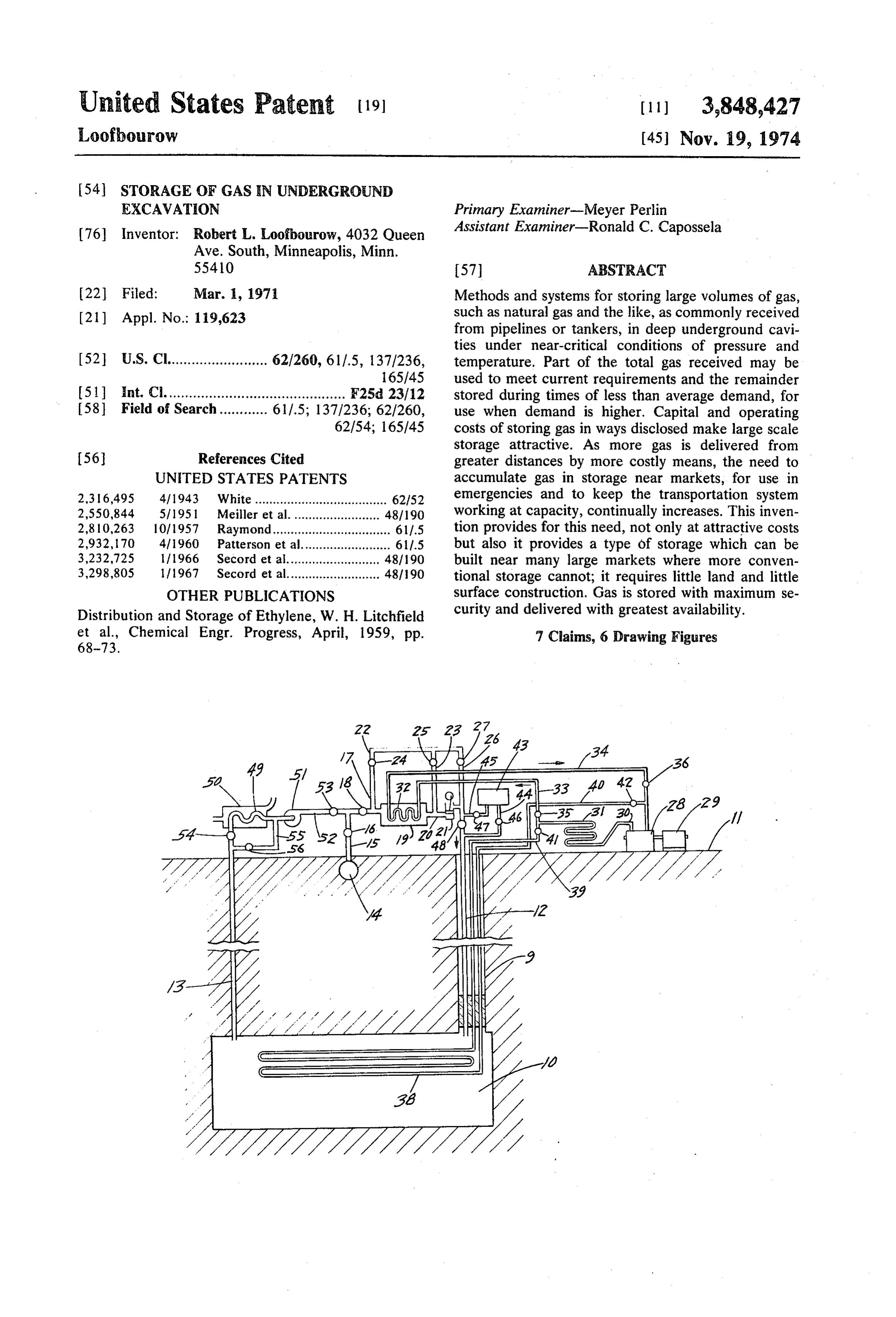
United States Patent (19) (11) 3,848,427 Loofbourow (45) Nov. 19, 1974
54 STORAGE OF GAS EN UNDERGROUND
EXCAVATION Primary Examiner-Meyer Perlin 76) Inventor: Robert L. Loofbourow, 4032 Queen Assistant Examiner-Ronald C. Capossela Ave. South, Minneapolis, Minn.
55410 57 ABSTRACT 22 Filed: Mar. 1, 1971 Methods and systems for storing large volumes of gas, (21) Appl. No.: 119,623 such as natural gas and the like, as commonly received from pipelines or tankers, in deep underground cavi ties under near-critical conditions of pressure and 52 U.S. Cl......................... 62/260, 611.5, 1371236, temperature. Part of the total gas received may be 65/45 used to meet current requirements and the remainder 51 int. Cl............................................. F25d 23/12 stored during times of less than average demand, for 58) Field of Search............ 611.5; 137/236; 62/260, use when demand is higher. Capital and operating 62/54; 165/45 costs of storing gas in ways disclosed make large scale storage attractive. As more gas is delivered from 56 References Cited greater distances by more costly means, the need to UNITED STATES PATENTS accumulate gas in storage near markets, for use in 2,316,495 4/1943 White ..................................... 62/52 emergencies and to keep the transportation system 2,550,844 51195 Meiller et al.. ... 48/190 working at capacity, continually increases. This inven 2,810,263 10/1957 Raymond........... ... 611.5 tion provides for this need, not only at attractive costs 2,932, 170 4/1960 Patterson et al......................... 611.5 but also it provides a type of storage which can be 3,232,725 ill 966 Secord et al.......................... 48/190 built near many large markets where more conven 3,298,805 lf 1967 Secord et al.......................... 48/190 tional storage cannot; it requires little land and little OTHER PUBLICATIONS surface construction. Gas is stored with maximum se Distribution and Storage of Ethylene, W. H. Litchfield curity and delivered with greatest availability. et al., Chemical Engr. Progress, April, 1959, pp. 7 Claims, 6 Drawing Figures
Page 2
PATENTL:CY 191974 3,848,427
| W - AZA-Z
S : \ Šs S 300 - --- - a- N ------- 2 & CS critisPONT ( o S2 g? - -
AOO N ------
ReeND -2OO -5O -foo -SO O 5O OO TampeArarura, of .
INVENTOR.
/ > Awaavaaécè4Aa-2 177 oarvas
Page 3
Drawing sheet — no readable text.
Page 4
Drawing sheet — no readable text.
Page 5
STORAGE OF GAS IN UNDERGROUND and pressure, thereby enabling much more gas to be EXCAVATION stored in a unit space and at moderate pressure. Whereas storage of these and similar gases in liquefied
This invention relates to the storage of gas in under form requires facilities for liquefaction and revaporiza ground chambers and more particularly to the under tion, this invention provides a means of storing nearly ground storage of gas at near-critical conditions. the same amount of gas in a unit space without the Thermodynamically, the critical temperature of a gas costly facilities and energy consumption required to is the temperature above which it cannot be liquefied convert the stored gas to liquid and back again to gas. at any pressure. The critical pressure is the pressure of The inflexible requirement of extreme low temperature the saturated vapor at the critical temperature or the 10 is also avoided.
pressure at which the gas and liquid coexist at the criti The percentage of methane in natural gas is generally cal temperature. Gases and their mixtures deviate from more than 85 percent and may be 95 percent or more. the classic gas laws (which show the relation between When a mixture of gases is cooled and compressed suf pressure, volume and temperature for an imagainary ficiently, liquid will condense. It will contain most of "perfect' gas) in that under some conditions more gas 15 the components of the gaseous mixture but their pro can be stored in a unit space than the gas laws indicate. portion in the liquid will not be the same as in the gas. This deviation and its rate of change are most favorable Before natural gas has been brought to the ultra-dense to gas storage at the critical temperature and pressure. condition here contemplated for storage, most of the impurities with relatively high boiling points will have
The "compressibility factor' of a gas is the measure 20 been liquefied. Small percentages of butane, propane, of this deviation. For various elemental gases and gase ethane and carbon dioxide may be present in the gas ous chemical compounds, each at its critical tempera supplied by a pipeline and are representative of this ture and pressure, the compressibility factor is between group. Depending on the composition of the gas as re 0.3 and 0.19, that is, the volume of space occupied by ceived, provision may be made to separate any frac a unit volume of gas at critical conditions is between 25 tions which liquefy as the gas is cooled. Impurities with 0.19 and 0.30 of the volume which a "perfect' gas relatively low boiling points, such as nitrogen, oxygen, would occupy at the same temperature and pressure. hydrogen, helium and argon will not condense, though The present invention is directed to the utilization of small amounts of these gases may dissolve in any liquids these properties for the advantageous storage of gases which do separate.
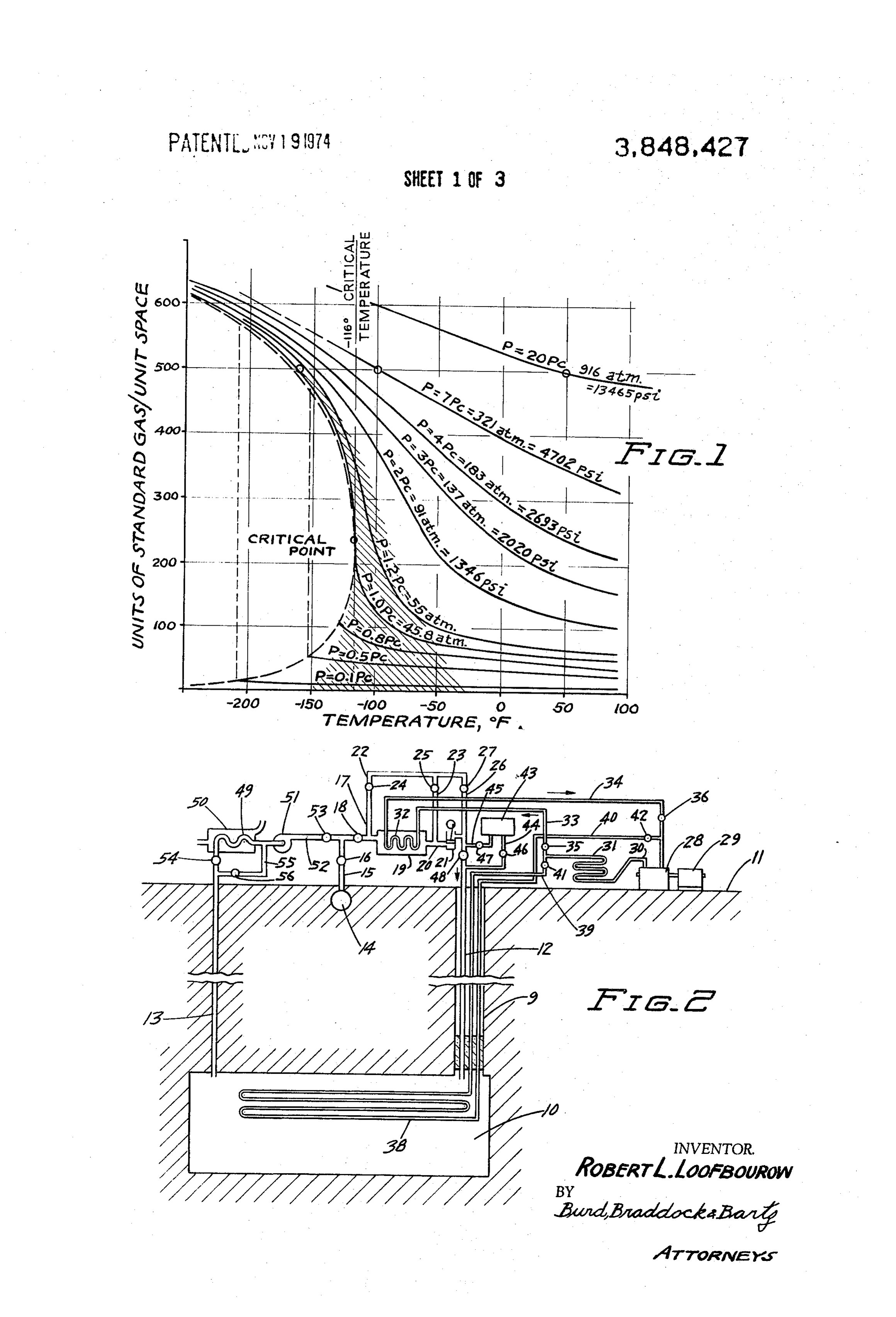
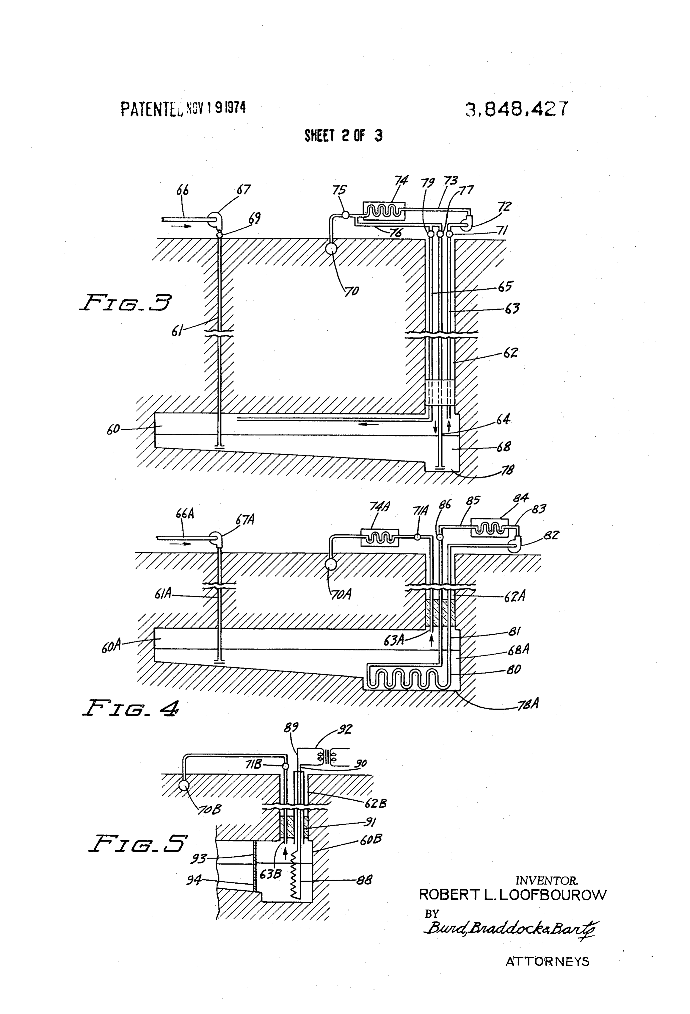
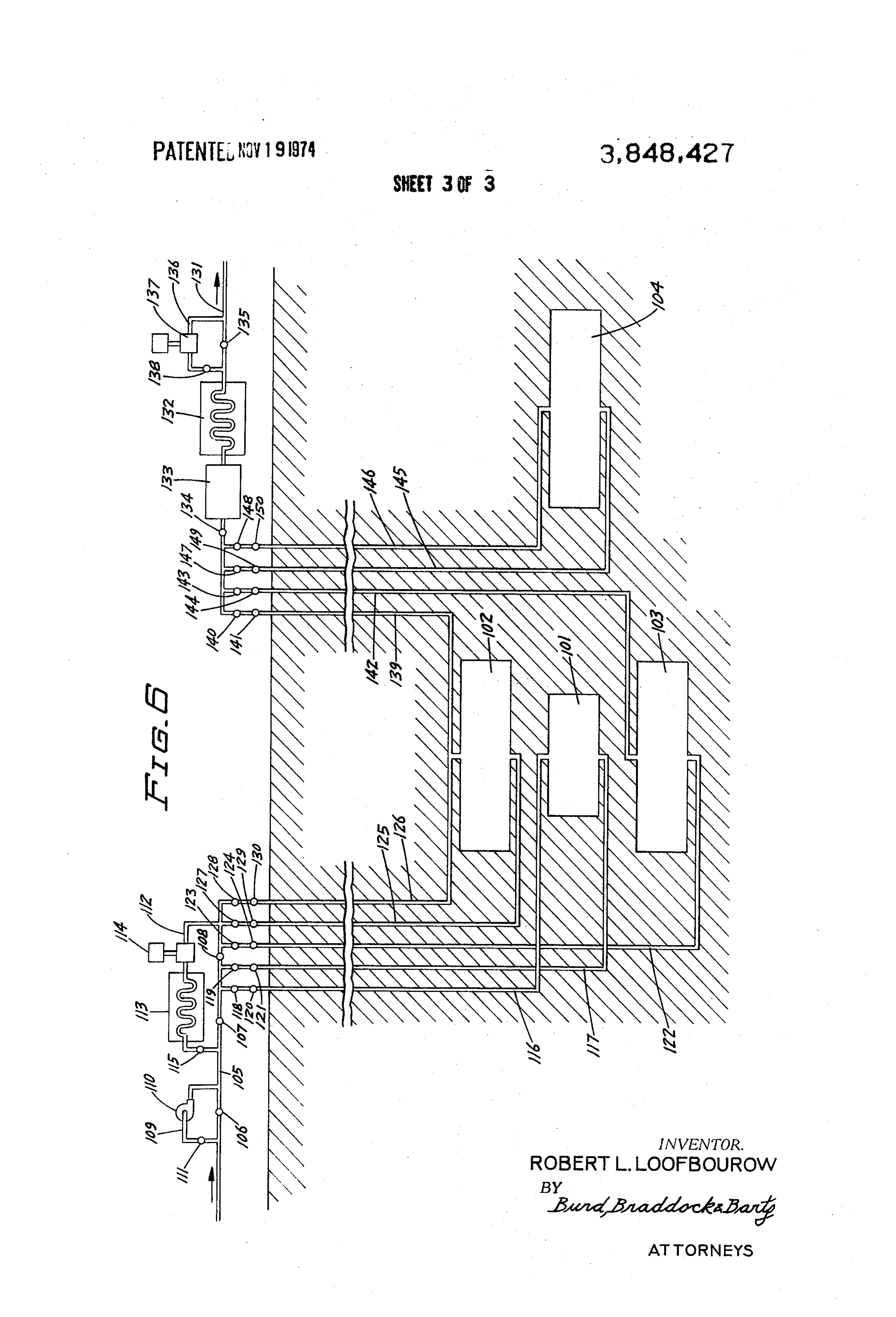
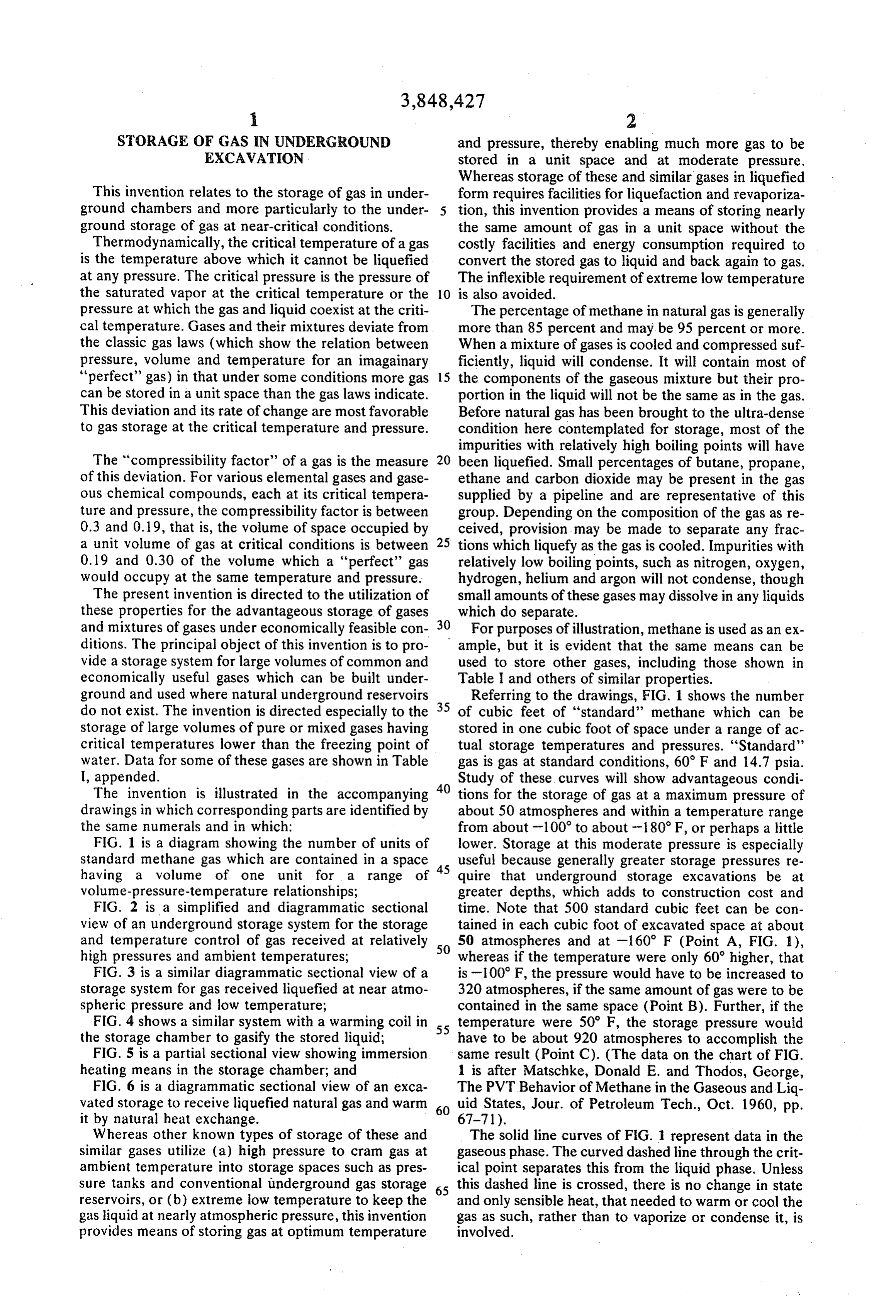
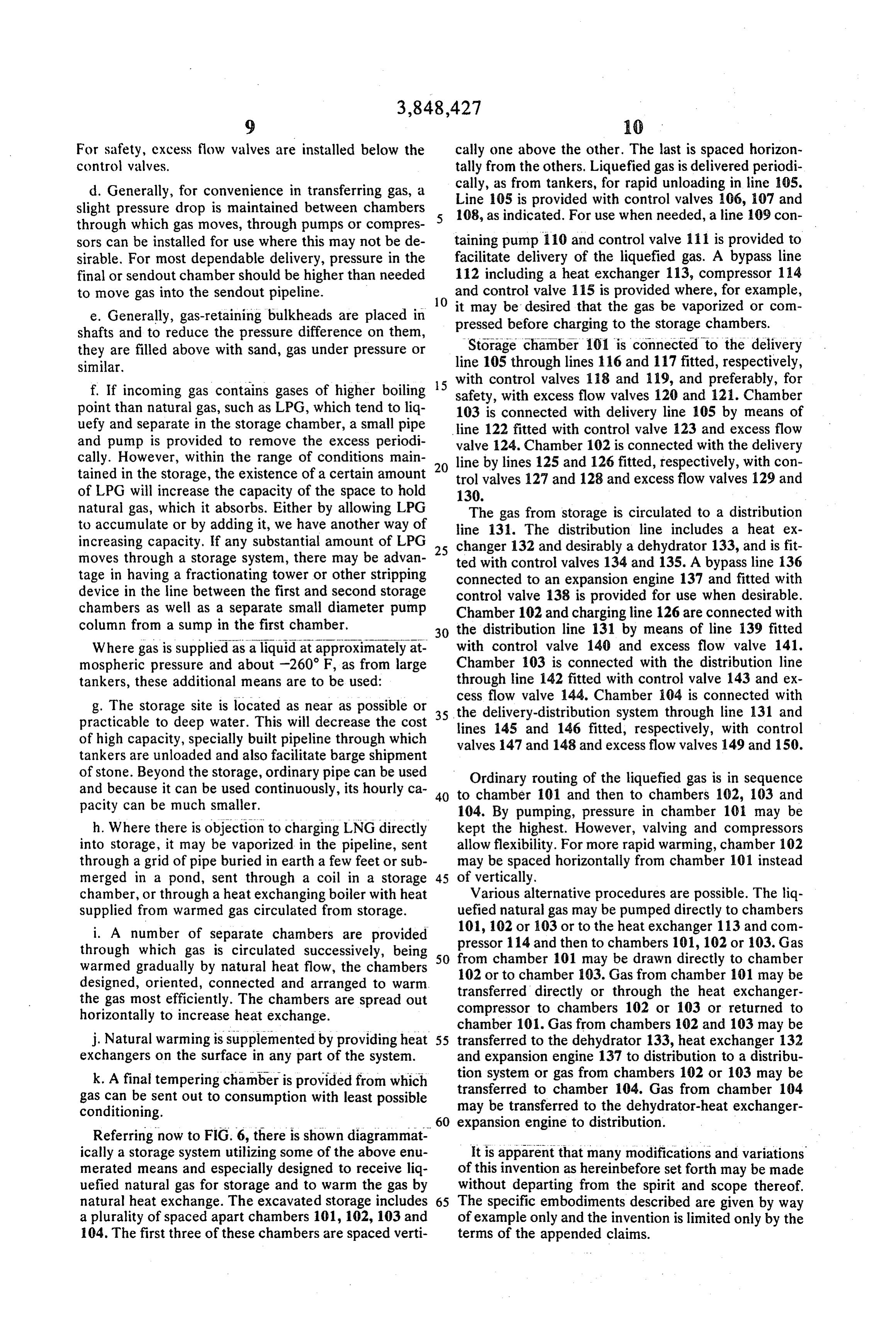
and mixtures of gases under economically feasible con 30 For purposes of illustration, methane is used as an ex ditions. The principal object of this invention is to pro ample, but it is evident that the same means can be vide a storage system for large volumes of common and used to store other gases, including those shown in economically useful gases which can be built under Table I and others of similar properties. ground and used where natural underground reservoirs 35 Referring to the drawings, FIG. 1 shows the number do not exist. The invention is directed especially to the of cubic feet of 'standard' methane which can be storage of large volumes of pure or mixed gases having stored in one cubic foot of space under a range of ac critical temperatures lower than the freezing point of tual storage temperatures and pressures. "Standard' water. Data for some of these gases are shown in Table gas is gas at standard conditions, 60 F and 14.7 psia. I, appended. Study of these curves will show advantageous condi The invention is illustrated in the accompanying 40 tions for the storage of gas at a maximum pressure of drawings in which corresponding parts are identified by about 50 atmospheres and within a temperature range the same numerals and in which: from about -100 to about -180° F, or perhaps a little FIG. 1 is a diagram showing the number of units of lower. Storage at this moderate pressure is especially standard methane gas which are contained in a space useful because generally greater storage pressures re having a volume of one unit for a range of quire that underground storage excavations be at volume-pressure-temperature relationships; greater depths, which adds to construction cost and FIG. 2 is a simplified and diagrammatic sectional time. Note that 500 standard cubic feet can be con view of an underground storage system for the storage tained in each cubic foot of excavated space at about and temperature control of gas received at relatively 50 50 atmospheres and at -160° F (Point A, FIG. 1), high pressures and ambient temperatures; whereas if the temperature were only 60' higher, that FIG. 3 is a similar diagrammatic sectional view of a is -100 F, the pressure would have to be increased to storage system for gas received liquefied at near atmo 320 atmospheres, if the same amount of gas were to be spheric pressure and low temperature; contained in the same space (Point B). Further, if the FIG. 4 shows a similar system with a warming coil in 55 temperature were 50 F, the storage pressure would the storage chamber to gasify the stored liquid; have to be about 920 atmospheres to accomplish the FIG. 5 is a partial sectional view showing immersion same result (Point C). (The data on the chart of FIG. heating means in the storage chamber; and 1 is after Matschke, Donald E. and Thodos, George, FIG. 6 is a diagrammatic sectional view of an exca The PVT Behavior of Methane in the Gaseous and Liq vated storage to receive liquefied natural gas and warm 60 uid States, Jour. of Petroleum Tech., Oct. 1960, pp. it by natural heat exchange. 67-71).
Whereas other known types of storage of these and The solid line curves of FIG. 1 represent data in the similar gases utilize (a) high pressure to cram gas at gaseous phase. The curved dashed line through the crit ambient temperature into storage spaces such as pres ical point separates this from the liquid phase. Unless sure tanks and conventional underground gas storage 65 this dashed line is crossed, there is no change in state reservoirs, or (b) extreme low temperature to keep the and only sensible heat, that needed to warm or cool the gas liquid at nearly atmospheric pressure, this invention gas as such, rather than to vaporize or condense it, is provides means of storing gas at optimum temperature involved.
Page 6
One principal object of this invention is to provide a ground excavations for the storage of gas under ordi type of storage for large volumes of methane and simi nary temperatures.
lar gases, which can be built and used where conven 3. Like other types of deep underground gas storages, tional reservoirs do not exist. Underground storage sys including the very useful conventional recharged natu tems for the storage of gases at or near their critical ral gas reservoirs, this type of storage affords a degree temperatures and pressures afford a number of advan of security distinctly superior to that of any storage re tages as compared with other types of storage facilities quiring extensive plant installations and storage tanks which can be built at such places. Other and equally or pits at the surface.
important objectives are (a) to provide an efficient way 4. Storage can be designed for expansion of capacity to receive gas as liquid in large quantity rapidly, as from 1 O without interruption of service, if and when required. tankers; (b) to warm a part of the gas received and send Reference to FIG. 1 shows that the quantity of gas it out more or less continuously for consumption; and which can be stored in unit space at a temperature of (c) hold other gas in dense form to meet emergency or -120° F (235 standard cubic feet per cubic foot of peak requirements. space) may be more than doubled if the storage tem 1. The costs of construction and operation can be 15 perature is reduced to -160° F with no significant moderate because: change of pressure (500 standard cubic feet per cubic a. Many units of gas, made dense by low temperature foot). Necessary but minor facilities, such as under and moderate pressure, can be stored in a unit of ground piping, can be built in anticipation of the space without requiring the high pressures and con 20 change so that the only major addition would be the in sequent great depths that would be needed if gas stallation of additional heat exchange and refrigerating were stored at ordinary temperatures. Where rock equipment on the surface.
is reasonably favorable, this enables the storage ex Depending on the manner in which gas is delivered cavations themselves to be made at costs favorable to the storage, and hence on its condition at delivery, as compared to the heavily insulated tanks of spe it is desirable that the equipment provided and even the cial metals or alloys or insulated covered pits which 25 design of the storage excavations be varied. Two cases may be used to store liquefied gas at the surface. are described under which it is assumed that gas is de With favorable conditions it is possible to make livered as:
space for 1/5 or even 1/10 of the cost of insulated 1. Compressed gas, ordinarily delivered from long tanks. The effect of large capacity in reducing the 30 distance pipelines at about 700 to 1,200 psi and about unit cost of underground excavations is greater 40° F to 80° F, and than in reducing those of surface storage tanks or 2. Liquefied gas, which may be delivered from tank pits. ers specially fitted out for the purpose, at substantially b. Heat exchange and more common refrigeration atmospheric pressure and about -260' F.
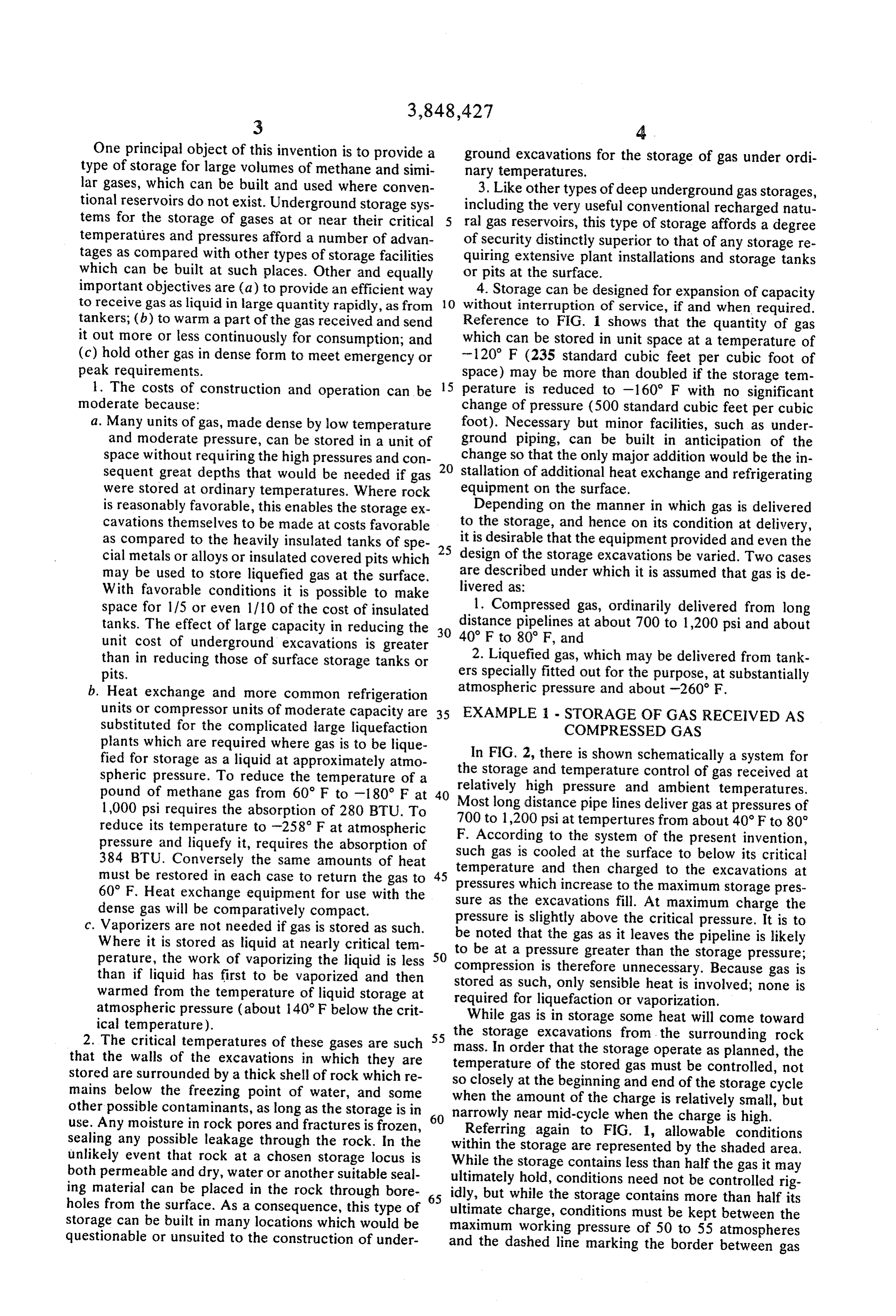
units or compressor units of moderate capacity are 35 EXAMPLE STORAGE OF GAS RECEIVED AS substituted for the complicated large liquefaction COMPRESSED GAS plants which are required where gas is to be lique fied for storage as a liquid at approximately atmo In FIG. 2, there is shown schematically a system for the storage and temperature control of gas received at spheric pressure. To reduce the temperature of a relatively pound of methane gas from 60° F to -180° F at 40 Most long distance high pressure and ambient temperatures. pipe lines deliver gas at pressures of 1,000 psi requires the absorption of 280 BTU. To 700 to 1,200 psi attempertures reduce its temperature to -258° F at atmospheric F. According to the system offrom the about 40°F to 80 present invention, pressure and liquefy it, requires the absorption of such gas is cooled at the surface to below its critical 384 BTU. Conversely the same amounts of heat temperature must be restored in each case to return the gas to 45 pressures which and then charged to the excavations at 60° F. Heat exchange equipment for use with the sure as the excavations increase to the maximum storage pres dense gas will be comparatively compact. fill. At maximum charge the c. Vaporizers are not needed if gas is stored as such. be noted that the gas as itthe pressure is slightly above critical pressure. It is to leaves the pipeline is likely
Where it is stored as liquid at nearly critical tem to be at a pressure greater than the perature, the work of vaporizing the liquid is less compression is therefore unnecessary.storage
Because pressure;
gas is than if liquid has first to be vaporized and then stored as such, only sensible heat is involved; none is warmed from the temperature of liquid storage at required for liquefaction or vaporization.
atmospheric pressure (about 140°F below the crit While gas is in storage some heat will come toward ical temperature).
2. The critical temperatures of these gases are such mass.storage 55 the excavations from the surrounding rock that the walls of the excavations in which they are temperature ofthat
In order the the storage operate as planned, the stored gas must be controlled, not stored are surrounded by a thick shell of rock which re so closely at the beginning and end of the storage cycle mains below the freezing point of water, and some when the amount of the charge is relatively small, but other possible contaminants, as long as the storage is in 60 narrowly near mid-cycle when the charge is high. use. Any moisture in rock pores and fractures is frozen, Referring again to FIG. 1, allowable conditions sealing any possible leakage through the rock. In the within the storage are represented by the shaded unlikely event that rock at a chosen storage locus is While the storage contains less than half the gas itarea. both permeable and dry, water or another suitable seal ultimately hold, conditions need not be controlled may ing material can be placed in the rock through bore 65 idly, but while the storage contains more than halfrig its holes from the surface. As a consequence, this type of ultimate charge, conditions must be kept between the storage can be built in many locations which would be maximum working pressure of 50 to 55 atmospheres questionable or unsuited to the construction of under and the dashed line marking the border between gas
Page 7
and liquid phases. The latitude of temperature at lower through chamber 19 where its temperature is lowered, pressures has several advantageous consequences: (a) and thence through pipes 20, 23 and 26 and valves 25, the heat exchanger-refrigeration plant does not need to 27 have capacity to cool gas to the lowest storage temper tionand10.48Inthrough input pipe 12 to the storage excava ature at the highest charging rate; charging conditions charged through pipeto13.demand, response the stored gas is dis
Optionally it is rewarmed in may follow any irregular path within the area indicated, coil 49 in chamber 50. The discharging gas is pumped and (b) if the storage operates for a number of years through compressor 51, pipe 52, valve 53, pipe 15 and within the area of greater latitude, it should be possible to determine the heat conductivity of the walls of the valve 16 back into pipeline 14 for distribution. excavations rather closely and so to select any addi O During the storage cycle the temperature of the gas tional heat-exchanger-refrigeration equipment with in the storage excavation may be controlled by several confidence. means used either singly or in combination. These are Referring now to FIG. 2, there is shown a storage ex as follows:
cavation 10 deep in the earth which is connected to the 1. Gas may be circulated by being withdrawn from surface 11 by means of an input casing 12 which ex 15 the storage excavation 10, pumped up through pipe 13 tends through shaft 9 and a discharge casing or shaft through bypass 55 and pump 51, pipes 52 and 17 and 13. The incoming gas is received through a pipeline 14 valves 53 and 18, recooled in the heat exchanger refrig which is connected by means of a pipe 15 valved at 16 eration unit 19 and pumped back through pipe 20 and and by another pipe 17 valved at 18 to a refrigerating valve 48 and pipe 12 to the storage excavation. The de chamber 19. Another pipe 20 connects the refrigerat 20 sign must be such that the gas circulates through all ing chamber 19 with the input pipe 12, through expan parts of the storage and should preferably permit the sion engine 21. Alternatively, the gas may bypass direction of circulation to be reversed. chamber 19 through pipes 22 and 23, valved at 24 and 2. A refrigerated fluid from the surface is circulated 25, respectively, or bypass chamber 19 and expansion through coil 38 and pipes 39 and 40, using natural con engine 21 through pipes 22 and 26. Pipe 26 is valved vection alone
at 27. Obviously, the gas may also be passed through 38 is shown asorconnected with forced circulation. Although coil to a refrigerating plant for chamber 19 while bypassing expansion engine 21. circulation of refrigerating gas, the same system may An independent refrigerating system is provided at optionally be used for circulating a cooled fluid, such the surface comprising a compressor 28 driven by a as brine, or the like.
suitable motor 29. The compressed refrigerating gas 30 from the compressor is conducted through a suitable 3. A small portion of the stored gas discharged from conduit 30 to a condenser or cooling tower 31. A re the refrigerating chamber 19 on the surface is liquefied frigerating coil 32 in the chamber 19 is connected to in the liquefaction plant 43 and injected as a liquid to the refrigerating plant by means of pipes 33 and 34 evaporate in the excavation and cool it. which are fitted with valves 35 and 36, respectively. 35 4. In anticipation of gradual warming of the stored Valve 35 is an expansion valve. The cooling effect of gas, depending on the heat conductivity of the wall, to the expanding gas flowing through the coil 32 in coun compensate for gradual warming, gas is introduced tercurrent flow against the incoming gas serves to cool somewhat less than the critical temperature, to an ex the gas to be stored as it is charged into the storage ex 40 tent that storage temperature will slightly exceed the cavation. critical temperature as the critical pressure is ap A further refrigerating coil 38 is optionally provided proached. Conversely, after somewhat more than half in the storage excavation 10. Coil 38 is connected to the gas has been withdrawn, the storage pressure will the refrigerating plant at the surface by means of pipes drop, the remaining gas will be cooled by expansion 39 and 40 passing down through shaft 9 and fitted with countering the heat naturally conducted through the valves 41 and 42, respectively. Valve 41 is an expan 45 walls, thus reducing the requirements of temperature sion valve. The cooling effect of the expanding gas regulation as no large change of temperature results. flowing through coil 38 functions to control the tem 5. During the period of charging, and especially the perature in the excavation. Further temperature con early trol means are provided in the form of a small liquefac 50 gas topart be of it when the pressure in the storage is low, charged is circulated through engines 21, not tion plant 43 connected to the input pipe 12 by means only to recover power but to gain the maximum cooling of a suitable conduit 44 and connected to pipe 20 from effect from the expansion. As the amount of gas in stor the refrigerating chamber by conduit 45. Conduits 44 age approaches its maximum and the storage pressure and 45 are fitted with valves 46 and 47, respectively.
A main valve 48 controls flow to input pipe 12. The 55 thenis closer to the pipeline pressure, gas is first cooled and discharge pipe 13 from the storage excavation is con expanded through an engine. nected to a heater coil 49 housed in a furnace 50 or 6. The described means of temperature control may other heating chamber connected to a compressor 51 be supplemented by insulating all or parts of the walls which in turn is connected by means of a pipe 52 pro of the storage excavation as may be desirable or neces vided with a valve 53 to connecting pipe 15 to the pipe sary in view of the storage cycle and the nature of the line 14 which may also serve to distribute the stored gas 60 rock mass surrounding the storage excavation. from the excavation upon discharge. Optionally, dis 7. The rock formation itself may contribute to tem charge pipe 13 may be valved at 54 and bypass 55, perature control where the excavations are made in valved at 56, is provided to bypass the heat exchanger cellular or other rock having less than average conduc and pass gas directly to the pump. tivity. Sites may be selected with this in mind. In the normal operation of the gas storage system of 65 8. Some temperature control is achieved by use of FIG. 2, gas received from pipeline 14 passes through compact storage chambers in order to reduce the ratio pipe 15 and valve 16, through pipe 17 and valve 18, of rock surface to storage volume.
Page 8
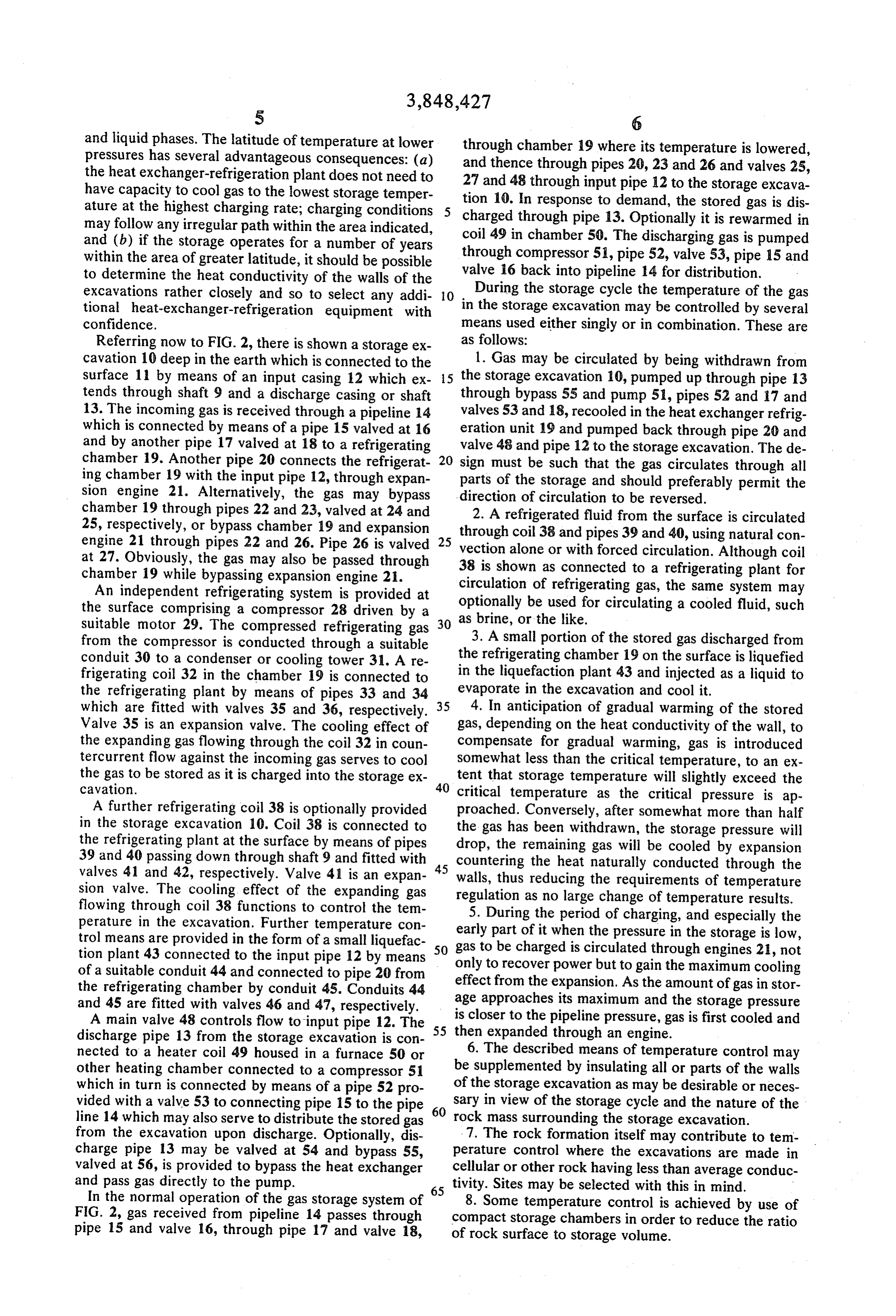
EXAMPLE 2 - STORAGE OF GAS RECEIVED pump 82 and pipe 83 to heat exchanger 84. Heat ex LIOUEFED changer 84 may be for the purpose of either heating or cooling and is connected to coil 80 through pipe 85 and
The choice between storing natural gas as high den valve 86. The heating or cooling fluid, as necessary, is sity gas or as liquid and gas depends on the condition circulated in a closed system for heating or cooling the of the gas as received by the owner of the storage and storage facility.
in view of the heat transfer characteristics of the rock 3. Electrically powered immersion heaters are placed at the site or sites available. If gas is received as liquid, through cased bore-holes into the liquid. As shown in as from tankers, and charged to storage as liquid at only FIG. 5, one or more immersion heating units 88 are dis a little more than atmospheric pressure and at about O posed in the chamber 60B at least partially submerged -260 F, the natural inflow of heat will gradually raise in the liquid phase of the stored gas. Heater 88 is con this temperature. While both liquid and gas exist in the nected by conductors 89 and 90 extending through a storage chamber, the pressure must equal the vapor closed casing 91 to an electrical heat generating source pressure of the liquid at the temperature existing. If the 92 at the surface.
storage is fully charged and then shut in for a long pe 15 4. To make heating most effective, its effect may be riod, pressure might have to be controlled so that the confined by baffles, as also shown in FIG. 5. Vertical planned working pressure would not be exceeded. baffle 93 having one or more openings 94 adjacent the However, all rocks are poor conductors of heat, some floor of chamber 60B confines the heat of heater 88 to indeed being rather good insulators. Normal gas with the compartment adjacent the discharge 63B to distri drawals, even at low seasonal rates, may keep storage 20 bution pipeline 70B while still permitting inflow of temperature undesirably low. The natural heat inflow colder stored gas to that compartment. is allowed to warm the stored liquid so that it will va 5. The pressure on the stored liquid may be reduced, porize, or may be vaporized more readily as required thus lowering the temperature at which it vaporizes. for withdrawal. 6. Sites may be sought in granite or other more than In FIG. 3, there is shown schematically a system for 25 normally conductive rock.
the storage and temperature control of gas received as 7. Storage chambers may be designed to afford a high liquid at nearly atmospheric pressure. The storage ex surface to volume ratio, consistent with other design cavation 60 deep in the earth is connected to the sur conditions.
face by means of an input casing or shaft 61 and a dis It is also possible to displace liquid methane from the charge shaft 62 through which a plurality of discharge 30 storage excavations to the surface and vaporize it there. pipes 63,64 and 65 extend. The incoming gas delivered This can be done readily by pumping warm methane from a marine or vehicular tanker is pumped rapidly gas into the storage, thus increasing the pressure suffi through pipe 66 by pump 67 into the storage chamber ciently to raise a column of liquid to the surface, or sim 60 through inlet 61. The liquefied gas may exist in the ply by warming the storage to increase the pressure chamber both in liquid form, as at 68, and in gaseous 35 therein. The density of methane is: at-1 16°F and 45.8 form. Inlet 61 is valved at 69. atmospheres, critical temperature and pressure, spe The gas from storage is introduced for distribution to cific gravity of liquid and gaseous methane is 0.162, a pipeline 70. Gas in the vapor phase is withdrawn density is 10.1 lbs. perft. which produces a head of 70 through pipe 63, which is valved at 71, by pump 72 psi for each 1,000 feet of vertical height. through pipe 73 to a heat exchanger 74 where the gas 40 at-263°F and 1 atmosphere specific gravity of liquid is warmed, and thence to the pipeline. For temperature methane is 0.415, the density is 25.9 lbs. perft. which control of the storage chamber, valve 75 may be closed produces a head of 180 psi for each 1,000 feet of verti and the warmed gas from heat exchanger 74 circulated cal height.
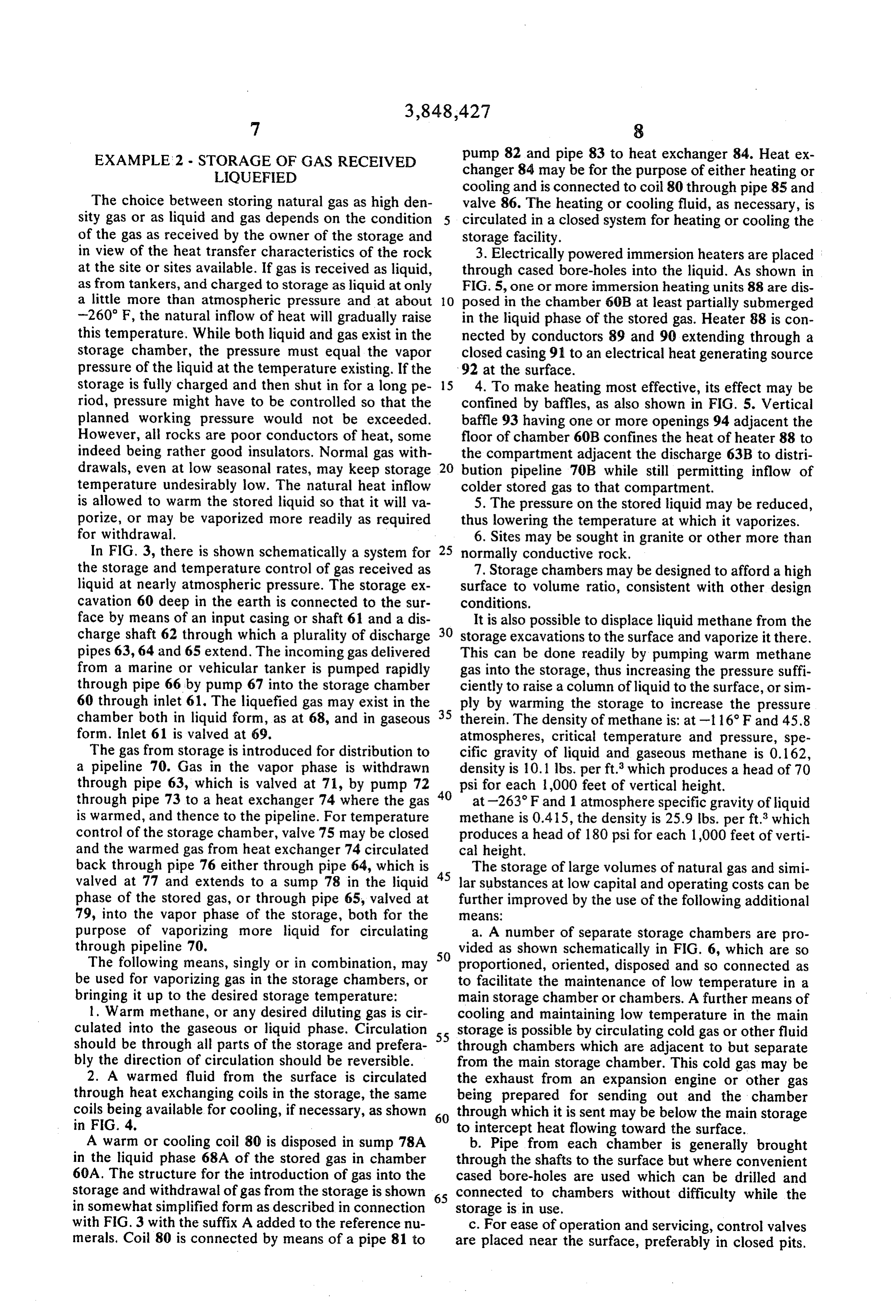
back through pipe 76 either through pipe 64, which is The storage of large volumes of natural gas and simi valved at 77 and extends to a sump 78 in the liquid 45 lar substances at low capital and operating costs can be phase of the stored gas, or through pipe 65, valved at further improved by the use of the following additional 79, into the vapor phase of the storage, both for the eaS purpose of vaporizing more liquid for circulating a. A number of separate storage chambers are pro through pipeline 70. vided as shown schematically in FIG. 6, which are so The following means, singly or in combination, may 50 proportioned, oriented, disposed and so connected as be used for vaporizing gas in the storage chambers, or to facilitate the maintenance of low temperature in a bringing it up to the desired storage temperature: main storage chamber or chambers. A further means of 1. Warm methane, or any desired diluting gas is cir cooling and maintaining low temperature in the main culated into the gaseous or liquid phase. Circulation storage is possible by circulating cold gas or other fluid should be through all parts of the storage and prefera 55 through chambers which are adjacent to but separate bly the direction of circulation should be reversible. from the main storage chamber. This cold gas may be 2. A warmed fluid from the surface is circulated the exhaust from an expansion engine or other gas through heat exchanging coils in the storage, the same being prepared for sending out and the chamber coils being available for cooling, if necessary, as shown 60 through which it is sent may be below the main storage in F.G. 4. to intercept heat flowing toward the surface. A warm or cooling coil 80 is disposed in sump 78A b. Pipe from each chamber is generally brought in the liquid phase 68A of the stored gas in chamber through the shafts to the surface but where convenient 60A. The structure for the introduction of gas into the cased bore-holes are used which can be drilled and storage and withdrawal of gas from the storage is shown 65 connected to chambers without difficulty while the in somewhat simplified form as described in connection storage is in use.
with FIG. 3 with the suffix A added to the reference nu c. For ease of operation and servicing, control valves merals. Coil 80 is connected by means of a pipe 81 to are placed near the surface, preferably in closed pits.
Page 9
For safety, excess flow valves are installed below the cally one above the other. The last is spaced horizon control valves. tally from the others. Liquefied gas is delivered periodi d. Generally, for convenience in transferring gas, a cally, as from tankers, for rapid unloading in line 105. slight pressure drop is maintained between chambers Line 105 is provided with control valves 106, 107 and through which gas moves, through pumps or compres 108, as indicated. For use when needed, a line 109 con sors can be installed for use where this may not be de taining pump 110 and control valve 111 is provided to sirable. For most dependable delivery, pressure in the facilitate delivery of the liquefied gas. A bypass line final or sendout chamber should be higher than needed 112 including a heat exchanger 113, compressor 114 to move gas into the sendout pipeline. O and control valve 115 is provided where, for example, e. Generally, gas-retaining bulkheads are placed in itpressed may be desired that the gas be vaporized or com before charging to the storage chambers.
shafts and to reduce the pressure difference on them, they are filled above with sand, gas under pressure or Storage chamber 101 is connected to the delivery similar. line 105 through lines 116 and 117 fitted, respectively, f. If incoming gas contains gases of higher boiling 15 with control valves 18 and 19, and preferably, for safety, with excess flow valves 120 and 121. Chamber point than natural gas, such as LPG, which tend to liq 103 is connected with delivery line 105 by means of uefy and separate in the storage chamber, a small pipe line 122 fitted with control valve 123 and excess flow and pump is provided to remove the excess periodi valve 124. Chamber 102 is connected with the delivery cally. However, within the range of conditions main line by lines 125 and 126 fitted, respectively, with con tained in the storage, the existence of a certain amount trol valves 127 and 128 and excess flow valves 129 and of LPG will increase the capacity of the space to hold 130.
natural gas, which it absorbs. Either by allowing LPG The gas from storage is circulated to a distribution to accumulate or by adding it, we have another way of line 131. The distribution line includes a heat ex increasing capacity. If any substantial amount of LPG 25 changer 132 and desirably a dehydrator 133, and is fit moves through a storage system, there may be advan ted with control valves 134 and 135. A bypass line 136 tage in having a fractionating tower or other stripping connected to an expansion engine 137 and fitted with device in the line between the first and second storage control valve 138 is provided for use when desirable.
chambers as well as a separate small diameter pump Chamber 102 and charging line 126 are connected with column from a sump in the first chamber, 30 the distribution line 131 by means of line 139 fitted Where gas is supplied as a liquid at approximately at with control valve 140 and excess flow valve 141. mospheric pressure and about -260 F, as from large Chamber 03 is connected with the distribution line tankers, these additional means are to be used: through line 142 fitted with control valve 143 and ex cess flow valve 144. Chamber 04 is connected with g. The storage site is located as near as possible or 35 the delivery-distribution system through line 131 and practicable to deep water. This will decrease the cost lines 145 and 146 fitted, respectively, with control of high capacity, specially built pipeline through which valves 147 and 148 and excess flow valves 149 and 150. tankers are unloaded and also facilitate barge shipment of stone. Beyond the storage, ordinary pipe can be used Ordinary routing of the liquefied gas is in sequence and because it can be used continuously, its hourly ca 40 to chamber 101 and then to chambers 102, 103 and pacity can be much smaller. 104. By pumping, pressure in chamber 101 may be h. Where there is objection to charging LNG directly kept the highest. However, valving and compressors into storage, it may be vaporized in the pipeline, sent allow flexibility. For more rapid warming, chamber 102 through a grid of pipe buried in earth a few feet or sub may be spaced horizontally from chamber 101 instead merged in a pond, sent through a coil in a storage 45 of vertically, chamber, or through a heat exchanging boiler with heat Various alternative procedures are possible. The liq supplied from warmed gas circulated from storage. uefied natural gas may be pumped directly to chambers i. A number of separate chambers are provided pressor 101, 102 or 103 or to the heat exchanger 113 and com through which gas is circulated successively, being 50 from 114 and then to chambers 101, 102 or 103. Gas warmed gradually by natural heat flow, the chambers chamber 101 may be drawn directly to chamber 102 or to chamber 103. Gas from chamber 101 may be designed, oriented, connected and arranged to warm. transferred the gas most efficiently. The chambers are spread out compressor directlyto or through the heat exchanger chambers 102 or 103 or returned to horizontally to increase heat exchange. chamber 101. Gas from chambers 102 and 103 may be j. Natural warming is supplemented by providing heat 55 transferred to the dehydrator 133, heat exchanger 132 exchangers on the surface in any part of the system. and expansion engine 137 to distribution to a distribu k. A final tempering chamber is provided from which tion system or gas from chambers 102 or 103 may be transferred to chamber 104. Gas from chamber 104 gas can be sent out to consumption with least possible may be transferred to the dehydrator-heat exchanger conditioning.
60 expansion engine to distribution.
Referring now to FIG. 6, there is shown diagrammat ically a storage system utilizing some of the above enu It is apparent that many modifications and variations merated means and especially designed to receive liq of this invention as hereinbefore set forth may be made uefied natural gas for storage and to warm the gas by without departing from the spirit and scope thereof. natural heat exchange. The excavated storage includes 65 The specific embodiments described are given by way a plurality of spaced apart chambers 101, 102, 103 and of example only and the invention is limited only by the 104. The first three of these chambers are spaced verti terms of the appended claims.
Page 10
TABLE I
CRTCA DATA FORWARIOUS GASES
Crit. Temp. Crit, Prs. Crit. Vol. Std. Vol. Ratic o F. Atmos. Cu. Ft./per lb. Cu. Ft./per h. Std. Vol.1 Crit. Vl. Argon - 1877 48.() 0.03 9.50 37 - Carbon Montxide. ()() - 220.3 34.5 0.053 357 256 Hydrogen - 399.8 12.8 ().56 88.6 365 Methane, CH, - 6.5 45.8 (),099 23.6 239 Nitrogen - 232.8 33.5 0.053 13.57 256 Nitric Oxide, NO - 36.7 650 0.03 12.66 4.08 Oxygen - 818 497 0.037 1.87 320 Air - 220.3 37.2 0.0457 3.08 286 Natural Gas - 87.4 46.
unra. wreh, Kurs. in ribook. kih art,. pp to. 42A, find .4mrr. for iur, it and book 193K, p. xiii
TArr arr ... rufa rr firit return. 'It'air fur pair arr rewrf"rrit reprarer attre of naturn una
The embodiments of the invention in which an exclu A. said storage facility comprises a plurality of stor sive property or privilege is claimed are defined as fol age chambers connected in series, and lows: B. the pressure in each of said storage chambers 1. A method of storage of pipeline gas received as 20 downstream from the first chamber is maintained compressed gas from a pipeline at pressures between at a level lower than the pressure in the next adja about 700 to 1,200 psi and temperatures between cent upstream chamber.
about 40 to 80°F in an excavated underground storage facility including at least one excavated underground ized Ain method
that:
according to claim 1 further character rock chamber, which method comprises: 25
A. said gas to be stored is natural gas,
A. cooling said gas to about -50 to -150°F and B. a small amount of liquefied petroleum gas (LPG) charging to said storage facility at pipeline pres is maintained in said storage chamber, and Sures,
B. when said facility contains about one half of its C. a portion of said natural gas is absorbed in said maximum capacity, increasing the pressure and 30 LPG, thereby increasing the capacity of said cham ber.
maintaining at moderately elevated level up to 7. A method of storage of pipeline gas received as about 2,500 psi, compressed gas from a pipeline at pressures between C. maintaining the facility at reduced temperature between about -50' and -150°F, whereby the gas about 700 to 1,200 psi and temperatures between is maintained for storage predominantly in the gas 35 about 40 to 80°F in an excavated underground storage eous state and is densified to store between about facility comprising at least one excavated underground 75 and 475 cubic feet of gas to each cubic foot of rock storage chamber and a plurality of other chambers adjacent to but separated from said storage chamber, storage space,
D. circulating stored gas to heat exchangers at which method comprises:
ground surface to cool the gas to maintain the stor 40 A. cooling said gas to about -50 to -150°F and age temperature, charging to said storage chamber at pipeline pres E. discharging said stored gas upon demand, and Sures,
F. after the quantity of stored gas has been reduced B. when said storage chamber contains about one to about one half of its maximum, decreasing the half of its maximum capacity, increasing the pres pressure while maintaining the temperature be 45 sure and maintaining at moderately elevated level tween about --50 and -150 F. up to about 2,500 psi, 2. A method according to claim 1 further character C. maintaining the storage chamber at reduced tem ized in that the stored gas is cooled by absorption of perature between about -50 and -150° F, heat in said heat exchangers by expansion of incoming whereby the gas is maintained for storage predomi gas from pipeline pressure to sendout trunkline pres 50 nantly in the gaseous state and is densified to store Sle. between about 75 and 475 cubic feet of gas to each 3. A method according to claim 1 further character cubic foot of storage space, ized in that the stored gas is cooled by absorption of D. circulating a heat exchanging fluid through said heat in said heat exchangers by expansion of incoming 55 other separated chambers to maintain the storage gas being charged to storage from pipeline pressure to temperature within said storage chamber, storage pressure. E. discharging said stored gas upon demand, and 4. A method according to claim 1 further character F. after the quantity of stored gas has been reduced ized in that gas is withdrawn from the top of said cham to about one half of its maximum, decreasing the ber and cooled gas is reintroduced at the bottom of said pressure while maintaining the temperature be chamber. tween about --50 and -150 F. 5. A method according to claim 1 further character ized in that:
Page 11
p; UNITED STATES PATENT OFFICE
CERTIFICATE OF CORRECTION
Patent No. 3,848, 427 Dated November 19, 1974
Inventor(s) Robert L. Loofbour ow
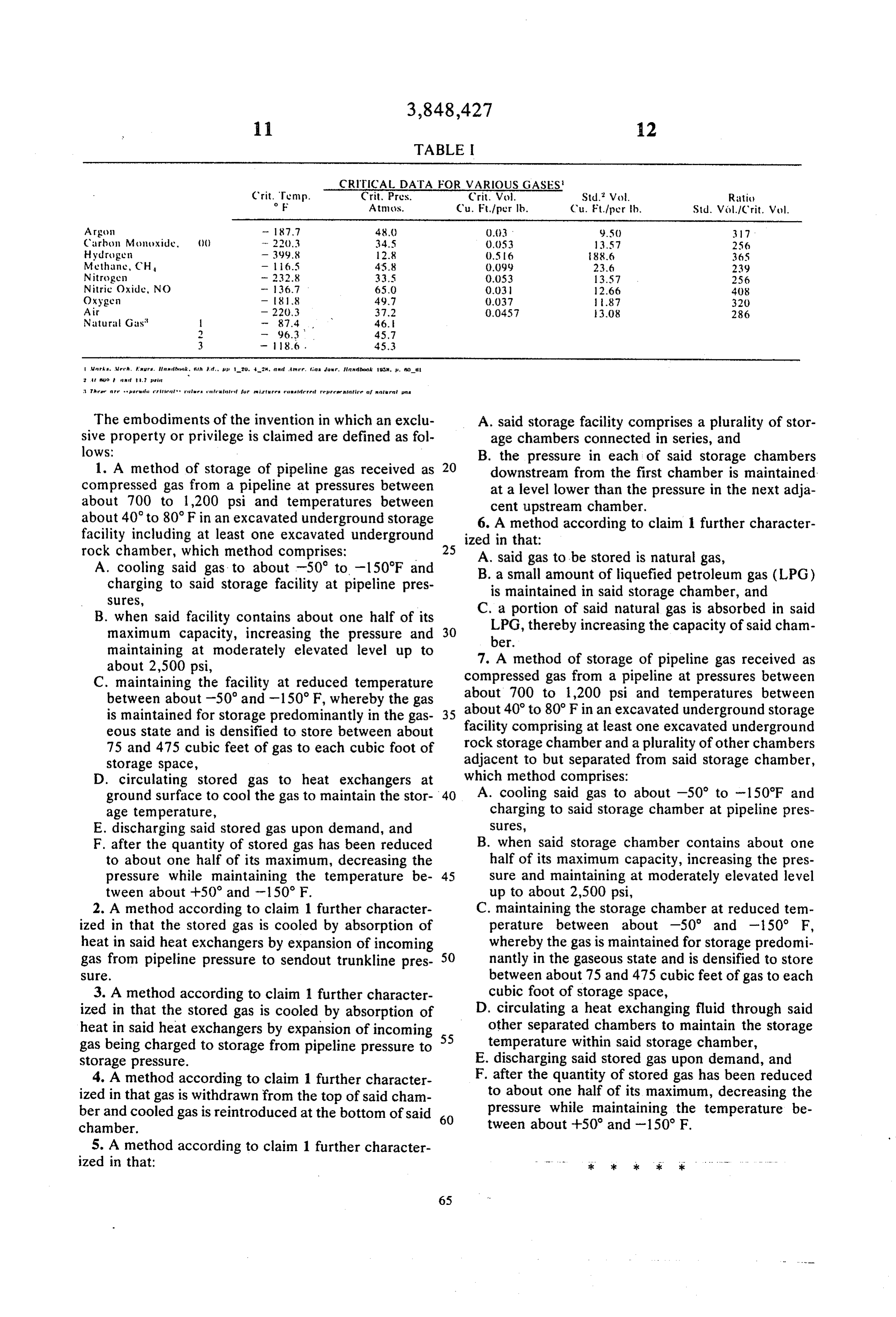
It is certified that error appears in the above-identified patent and that said Letters Patent are hereby corrected as shown below:
In the title, "EXCAVATION' should be pluralized.
Column 7, line 61, 'warm' should be --warming--.
Column 9, line 5, 'through' (second occurrence) should be
Signed and sealed this 14th day of January 1975.
(SEAL)
Attest :
Attesting Officer Commissioner of Patents
Provenance
- Collection
- Cited prior art
- Original PDF
- patentimages.storage.googleapis.com →
- Filed
- 1971-03-01
- Pages
- 11
- Method
- pdftotext (the PDF's own text layer) + pdftoppm 300dpi page scans
- Source
- Google Patents bibliographic record
- Granted
- 1974-11-19
- Inventors
- R Loofbourow
- Transcribed from
- patentimages.storage.googleapis.com →