patent · US3817689
Gas burner having lateral openings and a device for deflecting the flames upwards
18 June 1974
Page 1 — bibliographic record
United States Patent (19) 11 3,817,689 Capy (45) June 18, 1974 54 GAS BURNER HAVING LATERAL 3,279,455 10/1966 Corey................................. 4311347 OPENINGS AND A DEVICE FOR 3,580,733 5/1971 Ott...................................... 171129 DEFLECTING THE FLAMES UPWARDS 3,738,577 6/1973 Blanzy et al........................ 2391553
FOREIGN PATENTS OR APPLICATIONS
75 Inventor: Marcel Capy, Olivet, France 1,394,223 2/1965 France................................ 43 1349 73 Assignee: Compagnie Europeenne Pour 739,391 10/1932 France................................ 239/567 L'Equipement Menager CEPEM,
Paris, France Primary Examiner-Carroll B. Dority, Jr.
22 Filed: Nov. 15, 1972 Attorney, Agent, or Firm-Sughrue, Rothwell, Mion, Zinn and Macpeak
30) Foreign Application Priority Data A gas burner according to the invention comprises: a Nov. 15, 1971 France.............................. 71.408O1 mixing chamber having a thin, vertical, lateral wall perforated by outlets for the combustion mixture, a 52 U.S. Cl.................. 431/349, 239/553, 239/567, deflector disposed inside the mixing chamber, said de 239/568 flector having a slanting part which directs the flames 51 Int. Cl............................................. F23d 13/36 upwards in a slanting manner, and a cover coated with 58 Field of Search............ 431/349; 239/553,559, a self-cleaning catalytic enamel. The cover may be 2391567,568 made of metal or ceramic material. It may or may not constitute the deflector and it may or may not be de 56 References Cited tachable. The burner also comprises a crown for dis UNITED STATES PATENTS tributing the heat during cooking operations requiring low heat.
1,156,845 10/1915 James................................. 2391567 2,960,157 11 1960 Dolby................................. 43 11349 10 Claims, 8 Drawing Figures
Page 2
Drawing sheet — no readable text.
Page 3
Drawing sheet — no readable text.
Page 4
Drawing sheet — no readable text.
Page 5
GAS BURNER HAVING LATERAL OPENINGS AND
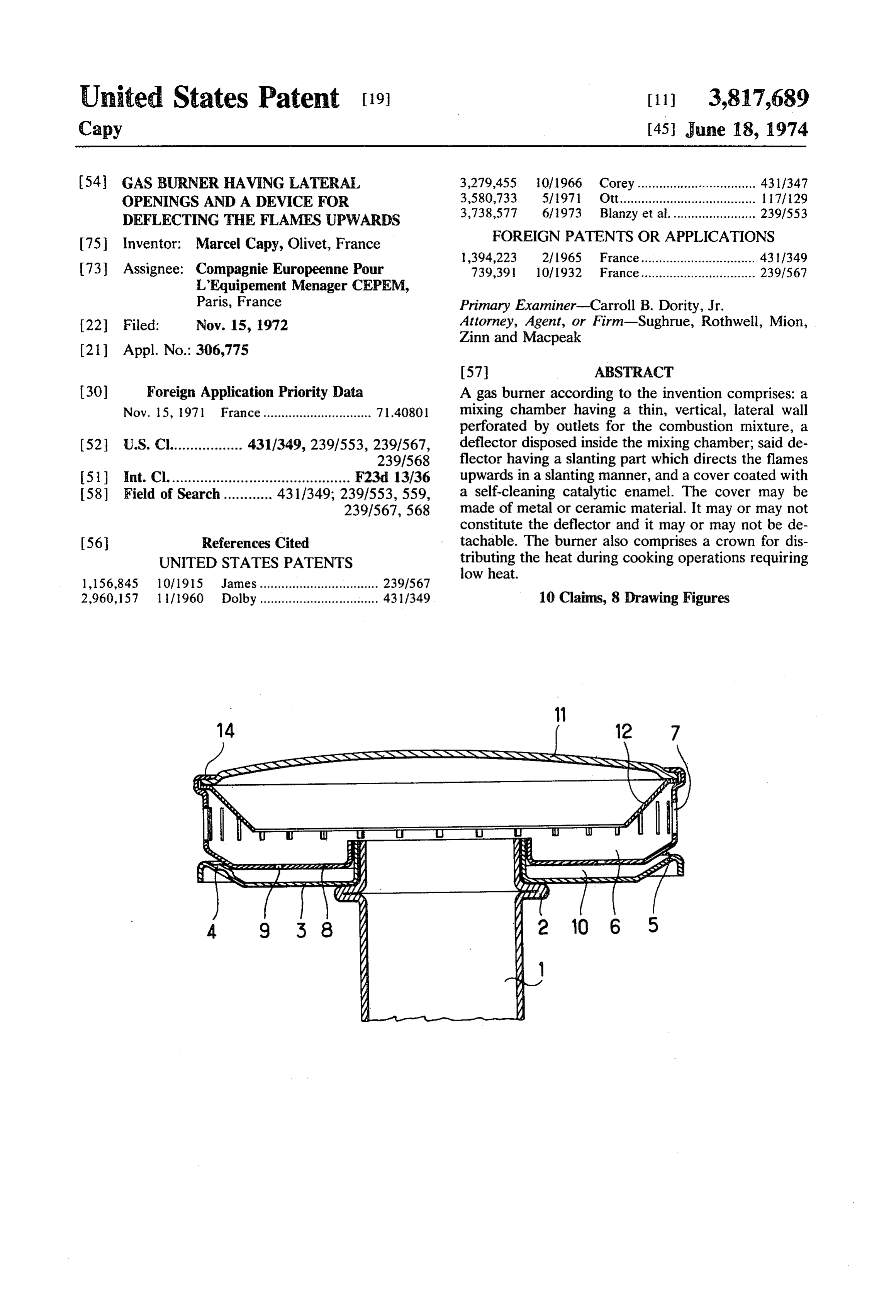
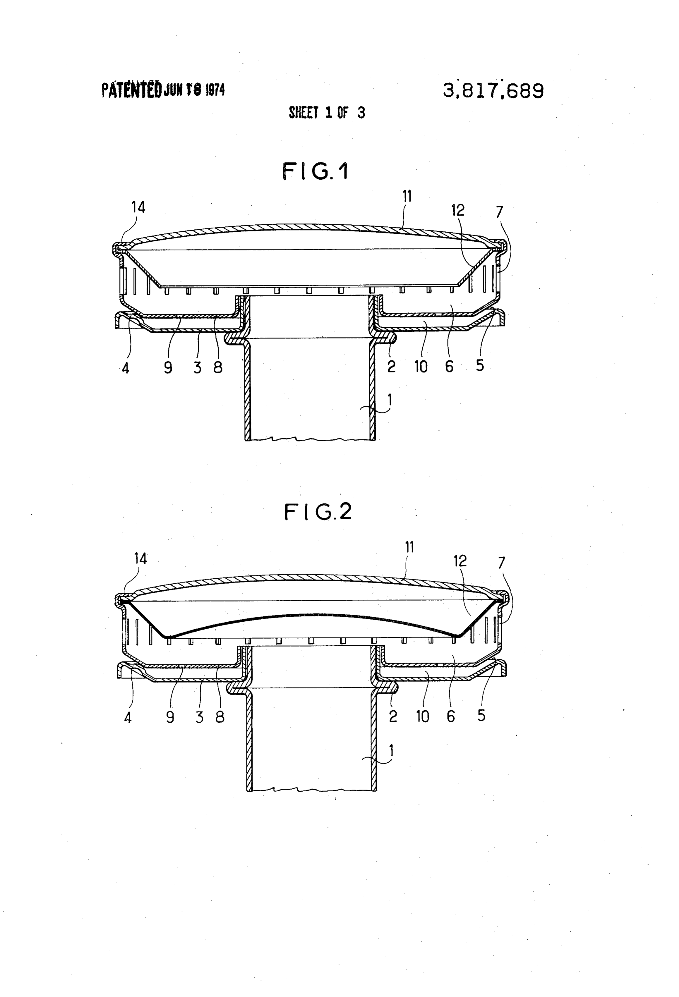
A DEVICE FOR DEFLECTING THE FLAMES BRIEF DESCRIPTION OF THE DRAWINGS UPWARDS FIG. 1 shows an axial sectional view of a gas burner according to the invention.
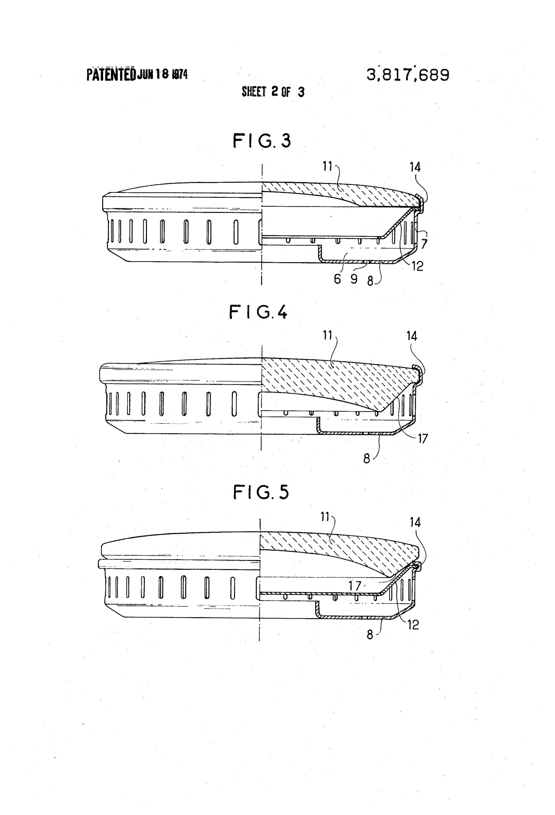
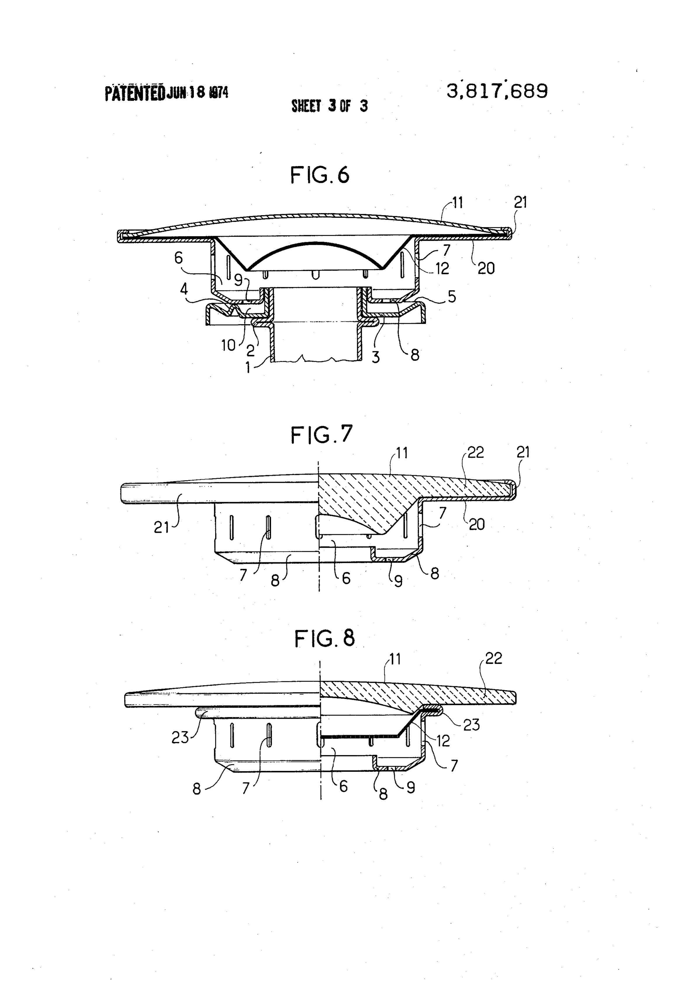
BACKGROUND OF THE INVENTION FIGS. 2-8 show variants of the burner according to the invention.
1. Field of the Invention
DESCRIPTION OF THE PREFERRED
The present invention relates to a gas burner com prising a mixing chamber having a substantially cylin EMBODIMENTS drical thin, lateral wall with vertical generatrices perfo 10 FIG. 1 shows an embodiment of a burner according rated by outlets for the combustion mixture. More par to the invention. It comprises a venturi 1, the collar 2 ticularly, it relates to circular burners for cooking of which supports a lower circular pan 3, with the ex Stoves. ception of 3 bosses such as 4, distributed at an angle of 2. Prior Art 120 from each other and serving to calibrate the pilot Gas burners with a thick cast metal wall are already opening 5. The pan 3 supports a circular mixing cham
ber, comprising known, in which it is possible to direct the flame up vertical, lateral wall, a burner pan 6 having a cylindrical, wards in a slanting manner by directing the apertures apertures 7 for the main provided with extended discharge in the cylindrical vertical wall. This insures better heat by apertures 9 supplyingflames. the Its base 8 is perforated expansion chamber 10, output and cleaner combustion by reducing the propor defined by the pan 3. The circular mixing chamber also tion of unburned and incompletely burned gas. Less ex comprises a slightly convex cover 11 and a frusto pensive burners of a simpler design and made of thin conical deflector 12. The cover and the deflector are sheet metal, are also known. Burners of this type have rendered integral with the wall of the mixing chamber the particular disadvantage of becoming soiled when by crimping the upper edge 14 of the wall over the the liquid in a container placed on the burner, boils 25 edges of these parts. The deflector 12 deflects the over. On the other hand, a certain amount of lining oc flames upwards in a slanting manner. In the absence of curs, i.e. the enamel cracks during operation of the this deflector they would be substantially horizontal. in burner when the burner cover is made of ordinary this way, the flames reach the base of the container to enamelled metal, due to the disparities in temperature 30 be heated, which is placed above the burner, closer to between the periphery and the centre. its axis than in the absence of the deflector. The flames are also longer. The heat output is thus improved and
SUMMARY OF THE INVENTION the rate of complete combustion increased, thereby The object of the present invention is to provide a gas avoiding the discharge of unburned hydrocarbons or burner with a cover adapted to withstand without dam 35 carbon monoxide.
age the thermal stresses produced by temperature dis Each of the parts constituting the burner can thus be parities during the operation thereof. made of inoxidable thin sheet metal adapted for regular Another object of the invention is to make it possible service conditions or suitably protected. The cover 11 is coated with catalytic enamel prior to the crimping to dismantle the cover. operation.
Yet another object of the invention is to eliminate the 40 In the embodiment shown in FIG. 2, the burner com cleaning process as the cover is self-cleaning. prises a venturi 1 having a peripheral collar 2 which The gas burner according to the invention is charac supports a lower circular pan 3, with the exception of terized in that it comprises a cover which is resistant to thermal stresses, and a deflector which is disposed in 45 3tobosses 4 distributed on the circumference and serving calibrate a pilot opening 5. The pan 3 supports a cir side the mixing chamber and which comprises a slant cular mixing chamber 6, comprising a burner pan 8 ing part for directing the flames upwards in a slanting having a cylindrical, vertical, lateral wall provided with lane. extended discharge apertures 7 for the main flames. Its Advantageously, the burner according to the inven base 8 is perforated by apertures 9 supplying the pilot tion also comprises at least one of the following fea 50 chamber 10. It also comprises a slightly convex cover tures: the cover is coated with a catalytic enamel, thus 11 coated with a catalytic enamel and a deflector 12 rendering the burner self-cleaning; the cover is made of having a frusto-conical lateral wall and an incurvated metal coated with a catalytic enamel; the burner cover solid base 13. The cover 11 and the deflector 12 are is made of ceramic material; the ceramic cover com rendered integral with the wall of the mixing chamber prises a lower wall having a slanting part forming a de 55 by crimping the upper edge 14 over the edges of these flector which directs the flames upwards in a slanting parts. The main flames are deflected upwards in a slant manner; the ceramic cover is arranged with a deflector ing manner by the deflector 12. This deflector 12 is made of thin metal, at the upper part of the burner ble solid and it defines the chamber 6 for mixing combusti body; the ceramic cover is placed on the burner, the chamber gas and primary air. The volume of the mixing deflector comprising a solid base; the cover comprises tor a flat may 60 be varied by giving the base of the deflec a horizontal part covering the flames in the low inten cording to the gasorused, shape a more or less incurvated shape ac its pressure and the capacity of sity area. the burner.
Other features of the present invention will be made apparent from the following detailed description of the 65 andIn the the embodiment represented in FIG. 3, the venturi preferred embodiments thereof, provided by way of prises a pilot chamber are not shown. The burner com circular mixing chamber 6. This comprises a non-limitative examples, and from the accompanying pan 8 having a cylindrical lateral wall provided with ex drawings representing said embodiments. tended apertures 7 for discharging the main flames. Its
Page 6
base 8 is perforated by apertures 9 supplying the pilot twice the inner diameter so as to cover the flames when chamber situated below the wall 8. The burner also the burner is operated at its minimum rate. comprises a slightly convex cover 11 and a deflector 12 FIG. 6 shows a burner having an enamelled metal having a frusto-conical lateral wall and a solid or hol cover. As in FIG. 1, it consists of a venturi, the collar low base. The cover 11 and the deflector 12 are ren of which supports a lower circular pan 3, with the ex dered integral with the wall of the mixing chamber by ception of 3 bosses such as 4. These bosses, which are crimping the upper edge 14 of this wall over the edges used to calibrate the pilot opening, are distributed at an of these parts. The main flames are deflected upwards angle of 120 from each other. The pan 3 supports a in a slanting manner by the deflector 12. circular mixing chamber comprising a burner pan 6 The cover 11 is made of ceramic material and it may O having a cylindrical, vertical, lateral wall provided with also be coated with a catalytic enamel. The use of a cat extended outlets 7 for the main flames. The horizontal alytic enamel allows the burner to be kept permanently crown 20 forms an extension of the vertical wall. The clean. base 8 of the burner pan is perforated by openings 9 FIG. 4 shows a burner of the same type, comprising supplying the expansion chamber limited by the pan 3. the same elements as that of FIG. 3 but in which the 15 cover 11 and the deflector 12 are replaced by a single The mixing chamber also comprises a deflector 12 ceramic part 11 forming both a burner cover and a de having a frusto-conical lateral wall, a convex base and flector redirecting the flames upwardly. For this rea a slightly convex cover 11. The cover 1 and the de son, the lower part of the member 11 is the same shape flector 12 are rendered integral with the pan 6 of the as the deflector in FIG. 2, i.e., it comprises at least one mixing chamber by crimping the upper edge 21 of the part shaped in the form of an inverted truncated cone crown of the pan over the edges of these parts. The directing the flames in a slanting manner upwards. The crown 20 may be flat or slightly convex. Its outer diam edge of the lateral wall 14 of the mixing chamber is eter is in the order of one-third to twice its inner diame crimped over the edge of the cover 11. ter which is also that of the vertical wall of the pan 6 FIG. 5 shows another variant of the burner in which 25 limiting the mixing chamber.
the cover 11 consists of a ceramic tablet which is sim FIG. 7 shows a burner with a ceramic cover 11. The ply placed on the burner. In this case, the deflector 12 reference numerals used in FIG.7 have the same mean made of thin sheet metal, is solid and is mounted at 14 ing as those used in FIG. 1 but the venturi has not been on the edge of the lateral wall of the burner body in represented. The ceramic cover also acts as a deflector, such a manner as to close the mixing chamber. The 30 the lower part of the cover having the same shape as edge of the tablet 11 comprises an inclined part 17 al the deflector shown in FIG. 1. The cover also com lowing the tablet to be applied to and centred on the prises a crown 22 which rests on the crown 20. deflector-burner body assembly. The cover 11 and the pan 6 of the mixing chamber FIGS. 6, 7 and 8 show embodiments of burners ac are joined by crimping the upper edge 21 of this pan cording to the invention, permitting a low intensity 35 over the edge of the cover.
heating action to be obtained more easily in containers FIG. 8 shows a burner with a ceramic cover 11. The used for the cooking operation known as "simmering' cover is detachable. The reference numerals used in and further permitting the heat to be distributed in a FIG. 8 have the same meaning as those used in FIGS. uniform manner under the base of the cooking utensils. 40 1, 6 and 7 but the venturi has not been represented. The ceramic cover 11 comprises a crown 22. It rests on
It is already known in the art to obtain this type of ef the assembly formed by the metal deflector 12 and the fect by interposing a concave metal screen between the pan 6 which are joined by crimping the upper edge 23 burner head and the container. The metal screen thus of this pan over the edge of the deflector. acts as a diffuser. Obviously, the sheet metal or ceramic cover may also When the metal screen is integral with a grill which 45 be enamelled with a catalytic enamel. supports the containers to be heated, this screen is The invention, which has been described, may obvi soldered to the grill and the soldered joints are situated ously be modified in various ways without departing in the flame when the burner is on “high.' For this rea from the scope of the invention and certain elements son it is necessary to use soldering materials having a 50 may be replaced by others having the same technical very high point of fusion. Furthermore, the incorpora function.
tion of this type of metal screen considerably compli What is claimed is:
cates the manufacture of the grill. It is possible to use 1. In a thin-walled gas burner comprising a mixing a metal screen known as a diffuser, which is placed on chamber defined by a substantially cylindrical, thin, lat the grill without a screen. A diffuser of this type, which eral wall with vertical generatrices perforated by verti generally has fairly large dimensions in order to support 55 cal slots for the combustion mixture, the improvement the cooking utensils, must be removed from the grill comprising cover means coated with a self-cleaning when the burner is fully "turned on.' catalytic enamel and separate deflector means disposed A gas burner according to the invention does not inside the mixing chamber adjacent to said slots for the have the disadvantages of known burners when used combustion mixture, said deflector means being at for "simmering.' Neither does a metal screen have to 60 tached to the upper edge of said lateral wall by a be interposed between the burner and the container to crimped portion and having a slanting part which di be heated. rects the flames upwards in a slanting manner. A gas burner adapted for low intensity cooking is 2. A burner according to claim 1, wherein the cover produced by surrounding the lateral wall of the mixing 65 means is made of ceramic material. chamber and the upper part of the same with a horizon 3. A burner accordingg to claim 1, wherein the cover tal crown which is flat or slightly concave toward the means and the deflector means are secured by crimping base. The outer diameter of the crown is one-third to the upper edge of the lateral wall thereto.
Page 7
4. A burner according to claim 2, wherein the ce flector means is joined to the upper edge of the vertical ramic cover means is placed on the burner and the de walls defining the mixing chamber and the cover means flector has a solid base. has a portion which extends laterally beyond the outer 5. A gas burner according to claim 1 wherein the diameters of the mixing chamber and the deflector outer diameters of the cover means and deflector S.
means are one third to twice the inner diameter of the 8. A gas burner according to claim 6, wherein the de vertical walls defining the mixing chamber. flector means and cover means are made of metal. 6. A gas burner according to claim 5 wherein the ver 9. A gas burner according to claim 7, wherein the lat tical wall defining the mixing chamber has a laterally erally extending portion of the cover is flat. extending upper portion and cover means and deflector O 10. A gas burner according to claim 7, wherein the means are attached to said laterally extending upper laterally extending portion of the cover is slightly con portion by crimping thereto. WiX.
7. A gas burner according to claim 1 wherein the de ck k k k k
Provenance
- Collection
- Cited prior art
- Original PDF
- patentimages.storage.googleapis.com →
- Filed
- 1972-11-15
- Pages
- 7
- Method
- pdftotext (the PDF's own text layer) + pdftoppm 300dpi page scans
- Source
- Google Patents bibliographic record
- Granted
- 1974-06-18
- Inventors
- M Capy; CO EUROP EQUIPEMENT MENAGER CE
- Transcribed from
- patentimages.storage.googleapis.com →