patent · US3183959
Gas burner ignition system
18 May 1965
Page 1
Drawing sheet — no readable text.
Page 2
Drawing sheet — no readable text.
Page 3
Drawing sheet — no readable text.
Page 4
United States Patent Office Patented May 18, 1965
prises an ignition element in proximity to the burner, a
GAS BURNER GNITION SYSTEM normally closed electromagnetic valve for controlling PatProducts
Romanei, Bronx, Englewood,
Company, N.Y., assignor
N.J.,to aRam Dornestic the partnership flow of gas to the burner and a temperature sensing element arranged to control the ignition element and the 5 valve. A primary switch is connected in series with
Filed Feb. 25, 1963, Ser. No. 260,790 the power source and the fuel valve to control the flow
of fuel. A secondary normally closed switch is con
The present invention relates generally to heating units nected in series with the ignition element and the power and specifically to an automatic ignition system for a O Source for Selective energization of the ignition element. gas fired device, which system offers improved safety and The temperature sensing element is positioned in prox performance while at the same time minimizing manu imity to the ignition element and to the gas burner and facturing costs. includes a solid metallic bar which expands in response In a great number of installations, automatic ignition to increased temperature and which is operatively en systems are required for the control of fuel flow and for gaged with the primary and secondary switches for ac the ignition of the fuel. Automatic ignition systems for tivating the primary switch in response to an initial in household use in appliances such as gas fired clothes crease in temperature and then the secondary switch in dryers must be versatile and should incorporate Safety response to further increase in temperature. Thus the features precluding the possibility of dangerous perform normally closed primary switch starts the flow of fuel ance. Although the ignition system according to the after an initial increase in temperature in the vicinity of present invention was designed specifically for gas fired 20 the igniter which is energized from the power source automatic clothes dryers, the concepts of the invention through the normally closed secondary switch. The may be incorporated in a number of other devices since burner then further heats the temperature sensing ele the ignition system for a gas dryer is of necessity ex ment to engage the secondary switch to deactivate the tremely versatile. Specifically, automatic gas dryers are 25 igniter. Linkage means are provided between the tem relatively simple appliances wherein a chamber is heated perature responsive bar and the primary and secondary by a flow of burning fuel which flow is triggered by a Switches to activate same in sequence as stated above. thermostatic control. The heating may be suspended by The above brief description as well as further objects, the temperature control mechanisms, by the timing features and advantages of the present invention will be device tolling the end of the cycle of operation of the best understood by reference to the following detailed machine, by the opening of the door to the appliance, description of a presently preferred embodiment when by interruption of electrical power to the appliance or by taken in conjunction with the accompanying drawings failure of an electrical component within the appliance. wherein:
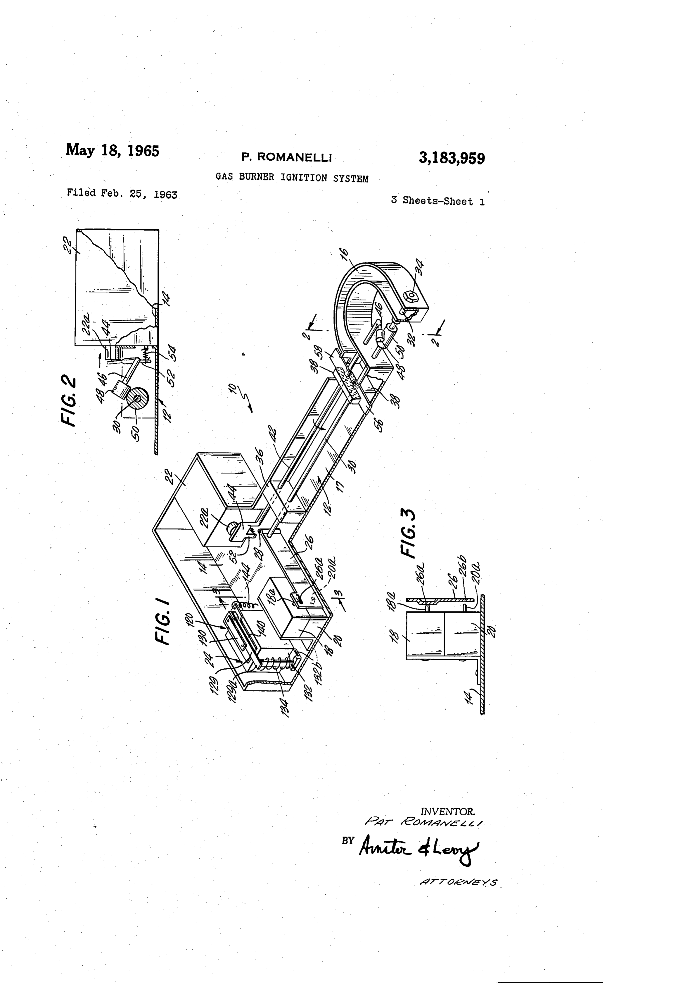
Any one of these circumstances must automatically F.G. 1 is a perspective view of a unitized automatic and immediately close the fuel valve. Furthermore, it fuel ignition system according to the present invention is desired that the ignition and control system be capable With a portion of the frame broken away to expose the of reactivating in a short period after halt of operations Several components;
without any escape of unburned fuel. Although a num FIG. 2 is a sectional view along the line 2-2 of FIG. 1 ber of automatic ignition systems have been designed and looking in the direction of the arrows illustrating the used commerically with some success, there exists a use of a vibrator as the ignition system in the present substantial need for improvements in reliability, oper 40 invention;
ational characteristics, costs of manufacture and simplic F.G. 3 is a sectional and partial view taken along the ity of installation into appliances. line 3-3 in FIG. 1 looking in the direction of the arrows Accordingly, it is generally the object of the present illustrating the particular link means incorporated in this invention to provide an ignition and control System for embodiment of the present invention to actuate the pri gas fired units of improved characteristics. Specifically, mary and Secondary switches;
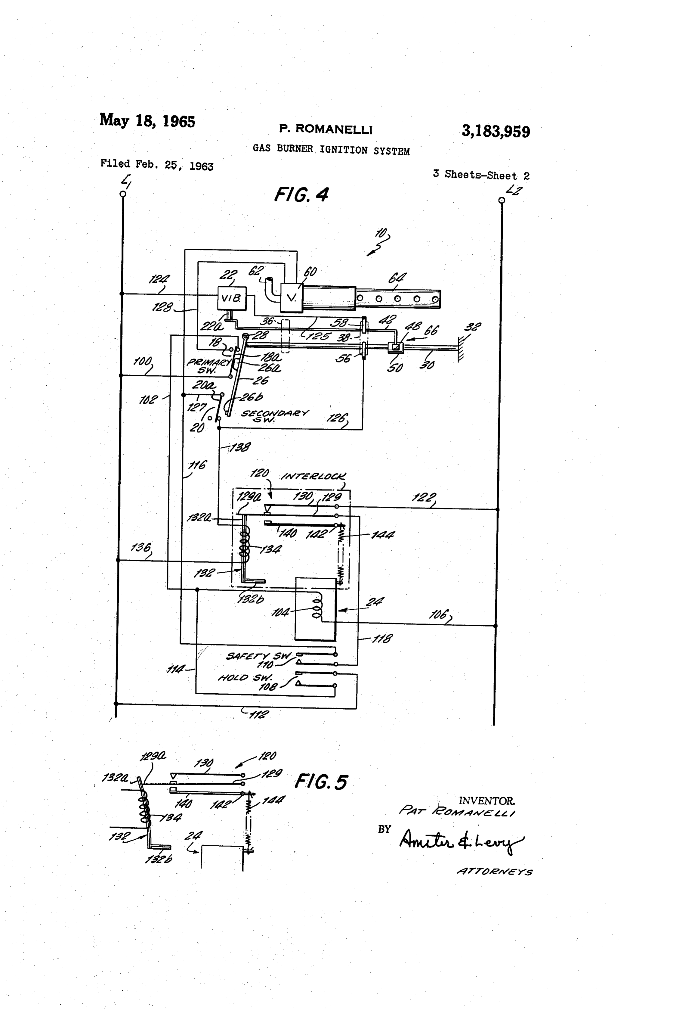
it is an object of the present invention to provide an auto FIG. 4 is a schematic and diagrammatic view of the matic ignition system to ignite and control the flow of circuitry incorporated in the ignition and control system fuel in a gas clothes dryer. according to the present invention illustrating the use of It is further within the contemplation of the present the vibrating ignition element as shown in FGS. 1, 2 invention to provide an automatic ignition system incor 50 and 3;
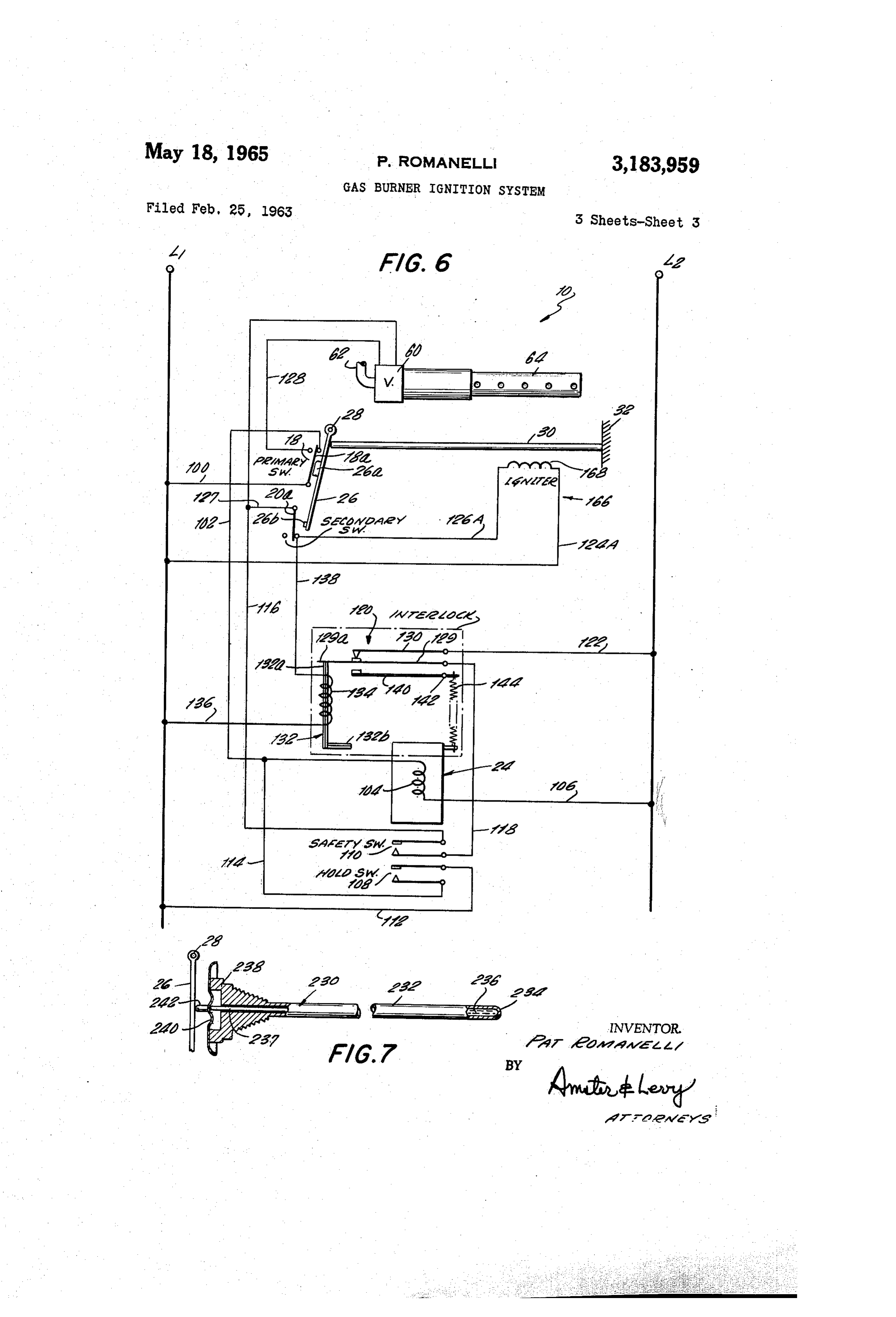
porating safety devices which completely prevent the FIG. 5 is a schematic view of the safety interlock flow of unignited fuel. shown in FIG. 4 illustrating the position of the various It is still further within the contemplation of the pres mechanisms in their condition after use to deactivate the ent invention to provide an ignition element incorporat fuel valve and ignition element; ing a temperature sensing mechanism of positive and FIG. 6 is a schematic representation of the circuit ac foolproof characteristics which will prevent the flow of cording to the present invention similar to that shown in fuel at all times other than when provision is made to . FIG. 4 with the exception of the use of a different ignition ignite such fuel. element from that in FIG. 4, specifically the use of a It is further within the contemplation of the invention resistance element rather than the sparking element of to provide an automatic ignition system which may be 60 FIG. 4; and constructed as one physical unit for easy installation FIG. 7 is an elevational and partially sectional view into a clothes dryer or other gas fired appliance. of a varying form of temperature sensing device for in In general, it is the object of the present invention to corporation into the system according to the present in provide an automatic ignition and fuel control device vention.
for use with automatic gas clothes dryers which incor 65 Referring now specifically to FIG. 1, there is shown porates a high degree of safety and reliability at a low one embodiment of the automatic ignition system accord manufacturing cost. ing to the invention, generally designated by the numeral In accordance with one illustrative embodiment of 50, all the components of which are mounted upon a the present invention there is provided an automatic fuel generally T-shaped frame 2 having at one end an en ignition system for a gas heater having a burner, a sole 70 larged chassis 14, a curved U-shaped frame 16 at the noid operated valve, and a source of power which is other end and an interconnecting leg 17. Mounted on activated when the heat is to go on. The system com the frame i2, at the chassis 4, and one on top of one
Page 5
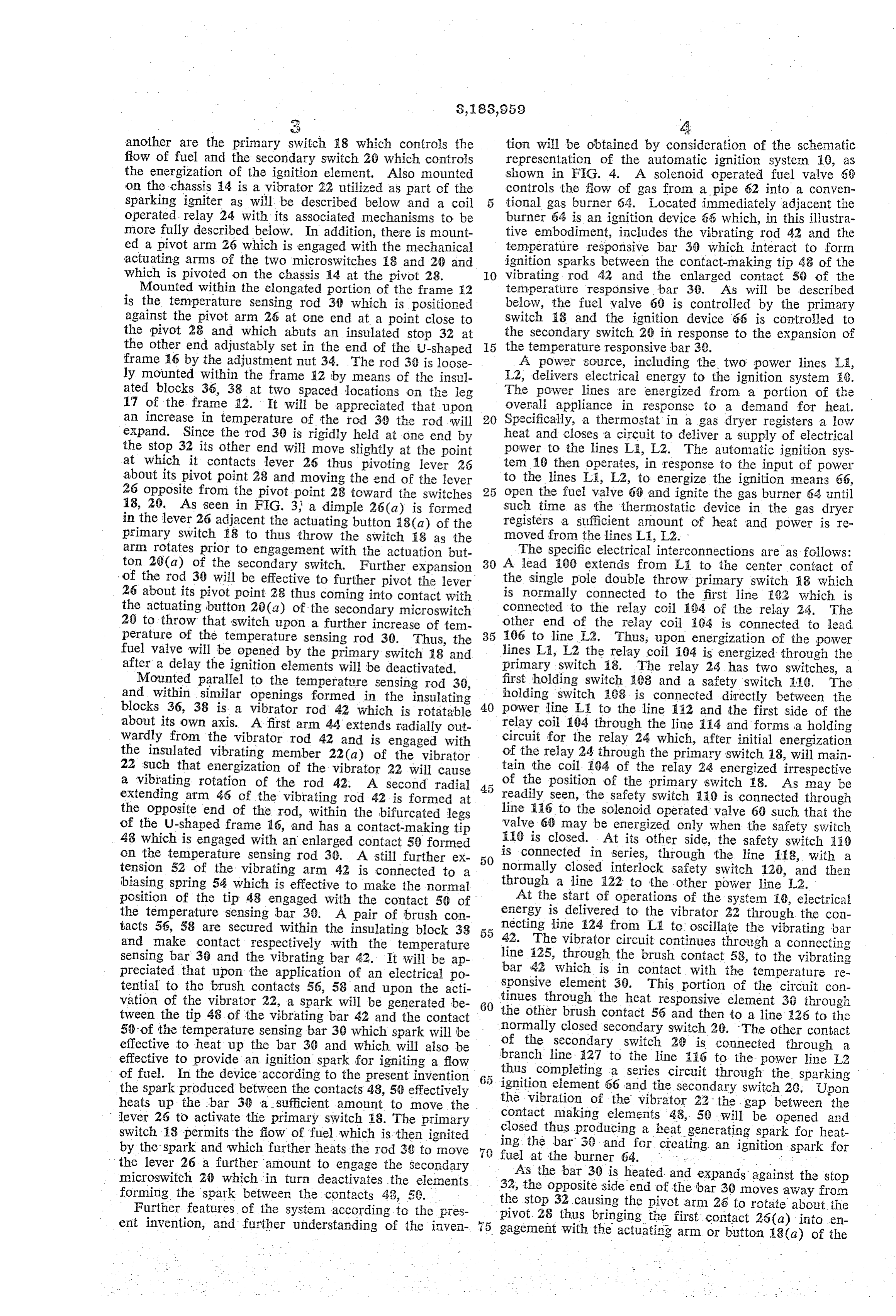
another are the primary switch 8 which controls the tion will be obtained by consideration of the schematic flow of fuel and the secondary switch 20 which controls representation of the automatic ignition systern 19, as the energization of the ignition element. Also mounted shown in FIG. 4. A solenoid operated fuel valve 60 on the chassis 14 is a vibrator 22 utilized as part of the controls the flow of gas from a pipe 62 into a conven sparking igniter as will be described below and a coil tional gas burner 64. Located immediately adjacent the operated relay 24 with its associated mechanisms to be burner 64 is an ignition device 66 which, in this illustra more fully described below. In addition, there is mount tive embodiment, includes the vibrating rod 42 and the ed a pivot arm 26 which is engaged with the mechanical temperature responsive bar 30 which interact to form actuating arms of the two microswitches 8 and 20 and ignition sparks between the contact-making tip 48 of the which is pivoted on the chassis 14 at the pivot 28. 10 vibrating rod 42 and the enlarged contact 50 of the Mounted within the elongated portion of the frame s2 temperature responsive bar 39. As will be described is the temperature sensing rod 30 which is positioned below, the fuel valve 60 is controlled by the primary against the pivot arm 26 at one end at a point close to switch 18 and the ignition device 66 is controlled to the pivot 28 and which abuts an insulated stop 32 at the secondary switch 20 in response to the expansion of the other end adjustably set in the end of the U-shaped 15 the temperature responsive bar 30. frame 6 by the adjustment nut 34. The rod 30 is loose A power source, including the two power lines Li, ly mounted within the frame 12 by means of the insul L2, delivers electrical energy to the ignition system i9. ated blocks 36, 38 at two spaced locations on the leg The power lines are energized from a portion of the 17 of the frame 12. It will be appreciated that upon overall appliance in response to a demand for heat. an increase in temperature of the rod 39 the rod will 20 Specifically, a thermostat in a gas dryer registers a low expand. Since the rod 30 is rigidly held at one end by heat and closes a circuit to deliver a Supply of electrical the stop 32 its other end will move slightly at the point power to the lines L1, L2. The automatic ignition SyS at which it contacts lever 26 thus pivoting lever 25 tem. 19 then operates, in response to the input of power about its pivot point 28 and moving the end of the lever to the lines L., L2, to energize the ignition means 66, 26 opposite from the pivot point 28 toward the switches open the fuel valve 66 and ignite the gas burner 64 until 18, 20. As seen in FIG. 3 a dimple 25(a) is formed such time as the thermostatic device in the gas dryer in the lever 26 adjacent the actuating button 8(a) of the registers a sufficient amount of heat and power is re primary switch E8 to thus throw the switch 18 as the moved from the lines L., L2.
arm rotates prior to engagement with the actuation but The specific electrical interconnections are as follows: ton 20 (a) of the secondary switch. Further expansion 30 A lead .00 extends from LF to the center contact of of the rod 30 will be effective to further pivot the lever the single pole double throw primary switch 8 which 26 about its pivot point 28 thus coming into contact with is normally connected to the first line E02 which is the actuating button 22(a) of the secondary microswitch connected to the relay coil is)4 of the relay 24. The 26 to throw that switch upon a further increase of tem other end of the relay coil 94 is connected to lead perature of the temperature sensing rod 30. Thus, the 106 to line L2. Thus, upon energization of the power fuel valve will be opened by the primary switch 18 and lines La, L2 the relay coil i84 is energized through the after a delay the ignition elements will be deactivated. primary switch 8. The relay 24 has two switches, a Mounted parallel to the temperature sensing rod 36, first holding switch 403 and a safety switch iEC. The and within similar openings formed in the insulating holding switch Ae8 is connected directly between the blocks 36, 38 is a vibrator rod 42 which is rotatable 40 power line L1 to the line 112 and the first side of the about its own axis. A first arm 44 extends radially out relay coil 104 through the line 14 and forms a holding wardly from the vibrator rod 42 and is engaged with circuit for the relay 24 which, after initial energization the insulated vibrating member 22(a) of the vibrator of the relay 24 through the primary Switch 18, will main 22 Such that energization of the vibrator 22 will cause tain the coil 164 of the relay 24 energized irrespective a vibrating rotation of the rod 42. A second radial of the position of the primary switch i8. As may be extending arm 46 of the vibrating rod 42 is formed at 45 readily seen, the safety switch 1i0 is connected through the opposite end of the rod, within the bifurcated legs line 6 to the solenoid operated valve 60 such that the of the U-shaped frame 16, and has a contact-making tip valve 68 may be energized only when the safety switch 43 which is engaged with an enlarged contact 59 formed i0 is closed. At its other side, the safety switch 50 on the temperature sensing rod 30. A still further ex 50 is connected in series, through the line 18, with a tension 52 of the vibrating arm 42 is connected to a normally closed interlock safety switch 20, and then biasing spring 54 which is effective to make the normal through a line 122 to the other power line L2. position of the tip 43 engaged with the contact 50 of At the start of operations of the system 6, electrical the temperature sensing bar 36. A pair of brush con energy is delivered to the vibrator 22 through the con tacts 56, 58 are secured within the insulating block 33 necting line 24 from L to oscillate the vibrating bar and make contact respectively with the temperature 42. The vibrator circuit continues through a connecting sensing bar 38 and the vibrating bar 42. it will be ap line 25, through the brush contact 58, to the vibrating preciated that upon the application of an electrical po bar 42 which is in contact with the temperature re tential to the brush contacts 56, 58 and upon the acti sponsive element 30. This portion of the circuit con vation of the vibrator 22, a Spark will be generated be 60 tinues through the heat responsive element 36 through tween the tip 48 of the vibrating bar 42 and the contact the other brush contact 53 and then to a line 226 to the 50 of the temperature sensing bar 30 which spark will be normally closed secondary switch 28. The other contact effective to heat up the bar 30 and which will also be of the secondary switch 28 is connected through a effective to provide an ignition spark for igniting a flow branch line 27 to the line A16 to the power line L2 of fuel. In the device according to the present invention thus completing a series circuit through the sparking the spark produced between the contacts 48, 58 effectively ignition element 66 and the secondary switch 26. Upon heats up the bar 39 a sufficient amount to move the the vibration of the vibrator 22 the gap between the lever 26 to activate the primary Switch 58. The primary contact making elements 48, 50 will be opened and switch 18 permits the flow of fuel which is then ignited closed thus producing a heat generating spark for heat ing the bar 36 and for creating an ignition spark for by the spark and which further heats the rod 39 to move 70 fuel at the burner 64. ... - the lever 26 a further amount to engage the Secondary As the bar 30 is heated and expands against the stop microswitch 20 which in turn deactivates the elements 32, the opposite side end of the bar 30 moves away from forming the spark between the contacts 43, 39.
Further features of the system according to the preS the stop 32 causing the pivot arm 25 to rotate about the pivot 28 thus bringing the first contact 26(a) into en ent invention, and further understanding of the inven 5 gagement with the actuating arm or button 18(a) of the
Page 6
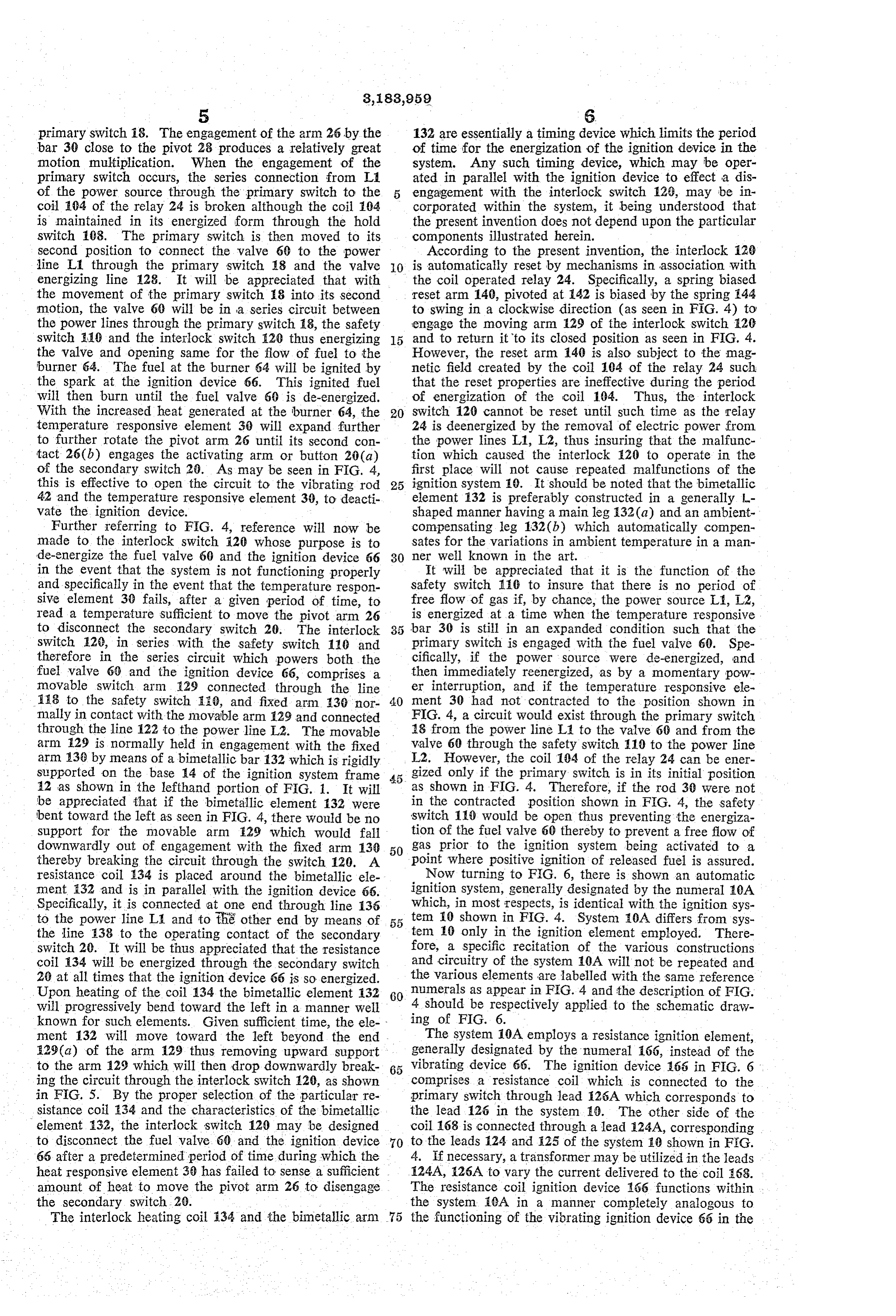
primary switch i8. The engagement of the arm 26 by the 132 are essentially a timing device which limits the period bar 30 close to the pivot 28 produces a relatively great of time for the energization of the ignition device in the motion multiplication. When the engagement of the system. Any such timing device, which may be oper primary switch occurs, the series connection from L. ated in parallel with the ignition device to effect a dis of the power source through the primary switch to the engagement with the interlock switch 29, may be in coil 104 of the relay 24 is broken although the coil 194 corporated within the system, it being understood that is maintained in its energized form through the hold the present invention does not depend upon the particular switch 103. The primary switch is then moved to its components illustrated herein.
Second position to connect the valve 60 to the power According to the present invention, the interlock 12 line L1 through the primary switch 18 and the valve O is automatically reset by mechanisms in association with energizing line 128. It will be appreciated that with the coil operated relay 24. Specifically, a spring biased the movement of the primary switch 18 into its second reset arm 140, pivoted at 42 is biased by the spring 144 motion, the valve 60 will be in a series circuit between to swing in a clockwise direction (as seen in FIG. 4) to the power lines through the primary switch 18, the safety engage the moving arm. 29 of the interlock switch E20 switch 10 and the interlock switch 120 thus energizing 15 and to return it to its closed position as seen in FIG. 4. the valve and opening same for the flow of fuel to the However, the reset arm 140 is also subject to the mag burner 64. The fuel at the burner 64 will be ignited by netic field created by the coil 104 of the relay 24 such the spark at the ignition device 66. This ignited fuel that the reset properties are ineffective during the period will then burn until the fuel valve 60 is de-energized. of energization of the coil 104. Thus, the interlock With the increased heat generated at the burner 64, the 20 switch 120 cannot be reset until such time as the relay temperature responsive element 30 will expand further 24 is deemergized by the removal of electric power from to further rotate the pivot arm 26 until its second con the power lines L1, L2, thus insuring that the malfunc tact 26(b) engages the activating arm or button 20 (a) tion which caused the interlock E20 to operate in the of the secondary switch 20. As may be seen in FIG. 4, first place will not cause repeated malfunctions of the this is effective to open the circuit to the vibrating rod 25 ignition system 10. It should be noted that the bimetallic 42 and the temperature responsive element 30, to deacti element 132 is preferably constructed in a generally -- vate the ignition device. shaped manner having a main leg 32(a) and an ambient Further referring to FIG. 4, reference will now be compensating leg 132(b) which automatically compen made to the interlock switch 120 whose purpose is to sates for the variations in ambient temperature in a man de-energize the fuel valve 60 and the ignition device 66 30 ner well known in the art.
in the event that the system is not functioning properly It will be appreciated that it is the function of the and Specifically in the event that the temperature respon safety switch 10 to insure that there is no period of sive element 30 fails, after a given period of time, to free flow of gas if, by chance, the power source L, IL2, Tead a temperature Sufficient to move the pivot arm 26 is energized at a time when the temperature Tesponsive to disconnect the secondary switch 20. The interlock bar 30 is still in an expanded condition such that the SWitch 12, in series with the safety switch 110 and primary switch is engaged with the fuel valve 60. Spe therefore in the series circuit which powers both the cifically, if the power source were de-energized, and fuel Valve 60 and the ignition device 66, comprises a then immediately reenergized, as by a momentary pow novable switch arm 29 connected through the line er interruption, and if the temperature responsive ele 1f8 to the Safety Switch 20, and fixed arm 39 nor 40 ment 30 had not contracted to the position shown in mally in contact with the movable arm 129 and connected FIG. 4, a circuit would exist through the primary switch through the line 122 to the power line L2. The movable 18 from the power line L1 to the valve 60 and from the arm 29 is normally held in engagement with the fixed valve 60 through the safety switch 110 to the power line arm 138 by means of a bimetallic bar 132 which is rigidly L2. However, the coil 104 of the relay 24 can be ener Supported on the base 4 of the ignition system frame 45 gized only if the primary switch is in its initial position 42 as shown in the lefthand portion of FIG. 1. It will as shown in FIG. 4. Therefore, if the rod 30 were not be appreciated that if the bimetallic element 132 were in the contracted position shown in FIG. 4, the safety bent toward the left as seen in FIG. 4, there would be no Switch 110 would be open thus preventing the energiza Support for the movable arm 529 which would fall tion of the fuel valve 60 thereby to prevent a free flow of downwardly out of engagement with the fixed arm 13 50 gas prior to the ignition system being activated to a thereby breaking the circuit through the switch 20. A point where positive ignition of released fuel is assured. resistance coil 34 is placed around the bimetallic ele Now turning to FIG. 6, there is shown an automatic ment 32 and is in parallel with the ignition device 66. ignition System, generally designated by the numeral E0A Specifically, it is connected at one end through line 136 which, in most respects, is identical with the ignition SyS to the power line L1 and to the other end by means of 55 tem 10 shown in FIG. 4. System E0A differs from sys the line 38 to the operating contact of the secondary tem. 6 only in the ignition element employed. There Switch 20. It will be thus appreciated that the resistance fore, a Specific recitation of the various constructions coil 34 will be energized through the secondary switch and circuitry of the System 10A will not be repeated and 20 at all times that the ignition device 66 is so energized. the various elements are labelled with the same reference Upon heating of the coil 134 the bimetallic element 132 60 numerals as appear in FIG. 4 and the description of FIG. Will progressively bend toward the left in a manner well 4 should be respectively applied to the schematic draw known for such elements. Given sufficient time, the ele ing of FIG. 6.
ment 132 will move toward the left beyond the end The System 10A employs a resistance ignition element, 529(a) of the arm 129 thus removing upward support generally designated by the numeral 166, instead of the to the arm 129 which will then drop downwardly break vibrating device 66. The ignition device 66 in FIG. 6 ing the circuit through the interlock switch 20, as shown comprises a resistance coil which is connected to the in FIG. 5. By the proper selection of the particular re primary switch through lead 126A which corresponds to sistance coil 134 and the characteristics of the bimetallic the lead 126 in the system 10. The other side of the element 32, the interlock switch 120 may be designed coil 168 is connected through a lead 24A, corresponding to disconnect the fuel valve. 60 and the ignition device 70 to the leads i24 and 25 of the system 2.0 shown in F.G. 65 after a predetermined period of time during which the 4. If necessary, a transformer may be utilized in the leads heat responsive element 38 has failed to sense a sufficient 24A, 26A to vary the current delivered to the coil E63. amount of heat to move the pivot arm 26 to disengage The resistance coil ignition device 66 functions within the secondary switch 20. the system iCA in a manner completely analogous to The interlock heating coil 34 and the bimetallic arm 75 the functioning of the vibrating ignition device 66 in the
Page 7
7 s
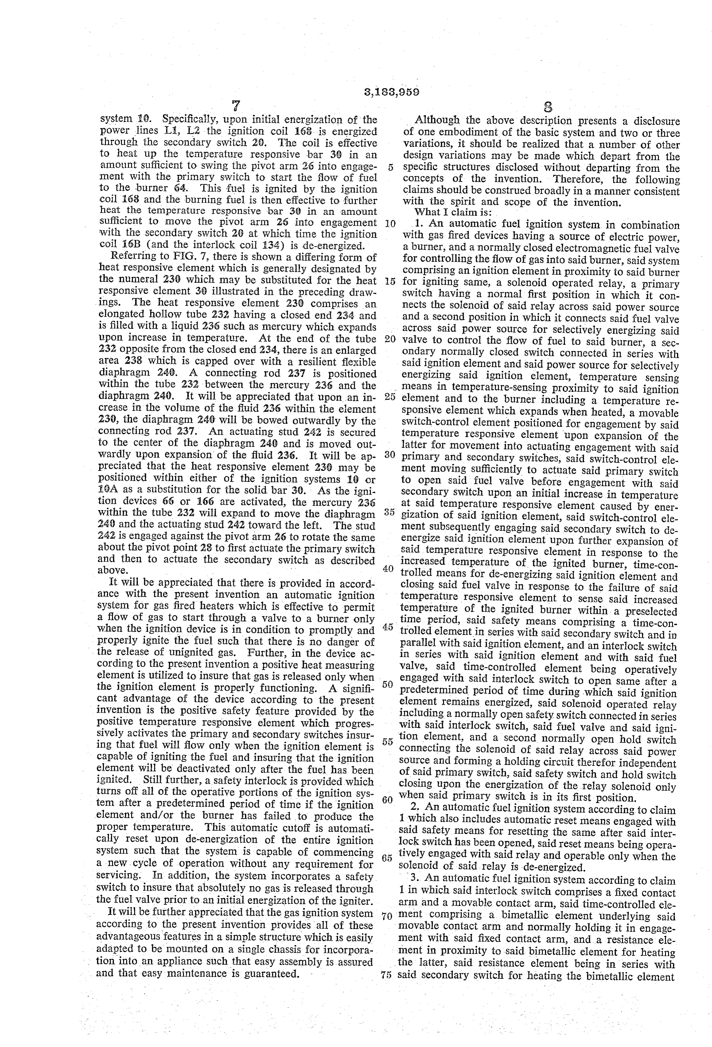
system 10. Specifically, upon initial energization of the Although the above description presents a disclosure power lines L., L2 the ignition coil 168 is energized of one embodiment of the basic system and two or three through the secondary switch 20. The coil is effective variations, it should be realized that a number of other to heat up the temperature responsive bar 30 in an design variations may be made which depart from the amount sufficient to Swing the pivot arm 26 into engage 5 specific structures disclosed without departing from the ment with the primary switch to start the flow of fuel concepts of the invention. Therefore, the following to the burner 64. This fuel is ignited by the ignition claims should be construed broadly in a manner consistent coil 168 and the burning fuel is then effective to further with the spirit and scope of the invention. heat the temperature responsive bar 30 in an amount What I claim is:
sufficient to move the pivot arm 26 into engagement O 1. An automatic fuel ignition system in combination with the secondary switch 26 at which time the ignition with gas fired devices having a source of electric power, coil. iSB (and the interlock coil 834) is de-energized. a burner, and a normally closed electromagnetic fuel valve Referring to FIG. 7, there is shown a differing form of for controlling the flow of gas into said burner, said system heat responsive element which is generally designated by comprising an ignition element in proximity to said burner the numeral 230 which may be substituted for the heat 5 for igniting same, a Solenoid operated relay, a primary responsive element 30 illustrated in the preceding draw switch having a normal first position in which it con ings. The heat responsive element 230 comprises an nects the solenoid of said relay across said power source elongated hollow tube 232 having a closed end 234 and and a second position in which it connects said fuel valve is filled with a liquid 236 such as mercury which expands across said power source for selectively energizing said upon increase in temperature. At the end of the tube 20 valve to control the flow of fuel to said burner, a sec 232 opposite from the closed end 234, there is an enlarged ondary normally closed switch connected in series with area 238 which is capped over with a resilient flexible said ignition element and said power source for selectively diaphragm 240. A connecting rod 237 is positioned energizing said ignition element, temperature sensing within the tube 232 between the mercury 236 and the means in temperature-sensing proximity to said ignition diaphragm 240. It will be appreciated that upon an in 25 element and to the burner including a temperature re crease in the volume of the fluid 236 within the element sponsive element which expands when heated, a movable 230, the diaphragm 240 will be bowed outwardly by the Switch-control element positioned for engagement by said connecting rod 237. An actuating stud 242 is secured temperature responsive element upon expansion of the to the center of the diaphragm 240 and is moved out latter for movement into actuating engagement with said wardly upon expansion of the fluid 236. It will be ap 30 primary and secondary switches, said switch-control ele preciated that the heat responsive element 239 may be ment moving Sufficiently to actuate said primary switch positioned within either of the ignition systems 10 or to open said fuel valve before engagement with said 18A as a substitution for the solid bar 30. As the igni Secondary Switch upon an initial increase in temperature tion devices 66 or 166 are activated, the mercury 236 at said temperature responsive element caused by ener within the tube 232 will expand to move the diaphragm 35 gization of Said ignition element, said switch-control ele 248 and the actuating stud 242 toward the left. The stud ment Subsequently engaging said secondary switch to de 242 is engaged against the pivot arm 26 to rotate the same energize said ignition element upon further expansion of about the pivot point 28 to first actuate the primary switch said temperature responsive element in response to the and then to actuate the secondary switch as described 40 increased temperature of the ignited burner, time-con above. trolled means for de-energizing said ignition element and It will be appreciated that there is provided in accord closing said fuel valve in response to the failure of said ance with the present invention an automatic ignition temperature responsive element to sense said increased system for gas fired heaters which is effective to permit temperature of the ignited burner within a preselected a flow of gas to start through a valve to a burner only time period, said safety means comprising a time-con when the ignition device is in condition to promptly and 45 properly ignite the fuel such that there is no danger of trolled element in series with said secondary switch and in parallel with said ignition element, and an interlock switch the release of unignited gas. Further, in the device ac in Series with said ignition element and with said fuel cording to the present invention a positive heat measuring valve, said time-controlled element being operatively element is utilized to insure that gas is released only when 50 engaged with said interlock switch to open same after a the ignition element is properly functioning. A signifi predetermined period of time during which said ignition cant advantage of the device according to the present element remains energized, said solenoid operated relay invention is the positive safety feature provided by the including a normally open safety switch connected in series positive temperature responsive element which progres with said interlock switch, said fuel valve and said igni sively activates the primary and secondary switches insur ing that fuel will flow only when the ignition element is 55 tion element, and a second normally open hold switch connecting the Solenoid of said relay across said power capable of igniting the fuel and insuring that the ignition Source and forming a holding circuit therefor independent element will be deactivated only after the fuel has been of Said primary switch, said safety switch and hold switch ignited. Still further, a safety interlock is provided which closing upon the energization of the relay solenoid only turns off all of the operative portions of the ignition sys 60 when said primary switch is in its first position. tem after a predetermined period of time if the ignition 2. An automatic fuel ignition system according to claim element and/or the burner has failed to produce the 1 Which also includes automatic reset means engaged with proper temperature. This automatic cutoff is automati said safety means for resetting the same after said inter cally reset upon de-energization of the entire ignition system such that the system is capable of commencing 65 lock tively
Switch has been opened, said reset means being opera engaged with said relay and operable only when the a new cycle of operation without any requirement for Solenoid of said relay is de-energized. servicing. In addition, the system incorporates a Safety 3. An automatic fuel ignition system according to claim switch to insure that absolutely no gas is released through 1 in which said interlock switch comprises a fixed contact the fuel valve prior to an initial energization of the igniter.
It will be further appreciated that the gas ignition system 70 arm and a movable contact arm, said time-controlled ele ment comprising a bimetallic element underlying said according to the present invention provides all of these movable contact arm and normally holding it in engage advantageous features in a simple structure which is easily ment with Said fixed contact arm, and a resistance ele adapted to be mounted on a single chassis for incorpora ment in proximity to said bimetallic element for heating tion into an appliance such that easy assembly is assured the latter, said resistance element being in series with and that easy maintenance is guaranteed. 75 said secondary switch for heating the bimetallic element
Page 8
- 9 O while said ignition element is energized and for moving said temperature responsive element comprises a solid said bimetallic element out of engagement with Said metallic bar mounted parallel to said vibrator rod and movable switch arm whereby to open said interlock switch having said contact portion at one end thereof, the other after said predetermined period of time when said second end of said bar being in engagement with said movable ary. Switch fails to open. ai 4. An automatic fuel ignition system according to claim 7. An automatic fuel ignition system in combination 3 which also includes automatic reset means for said with gas fired devices having a source of electric power, safety means, said reset means including a movable reset a burner, and a normally closed electromagnetic fuel valve arm positioned to engage said movable contact arm, for controlling the flow of gas into said burner, said sys means biasing said reset arm in a direction to engage said O tem comprising a unitary frame mounted adjacent said movable contact arm and move the latter into engagement burner, an ignition element mounted on said frame in with said fixed contact arm, said relay solenoid when proximity to said burner for igniting the latter, a primary energized holding said reset arm remote from said mov switch connected in series with said power source and able contact arm, whereby said reset arm is operable to said fuel valve for controlling the flow of fuel to said close said interlock switch only when said relay solenoid burner, said primary switch being normally biased to an is de-energized. open position and having a plunger depressible to close 5. An automatic fuel ignition system in combination said primary Switch, a secondary switch connected in series with gas fired devices having a source of electric power, a with said power source and said ignition element for ener burner, and a normally closed electromagnetic fuel valve gizing the latter, said secondary switch being normally for controlling the flow of gas into said burner, said biased to a closed position in which said ignition element System comprising a unitary frame mounted adjacent said is energized and having a plunger depressible to open burner, an ignition element mounted on said frame in said secondary switch, said primary and secondary switches proximity to said burner for igniting the latter, a primary being mounted adjacent each other on said frame with the Switch connected in series with said power source and plungers thereof in alignment, temperature sensing means said fuel valve for controlling the flow of fuel in said mounted on said frame in temperature-sensing proximity burner, said primary switch being normally biased to an to said ignition element and to said burner, including a open position and having a plunger depressible to close temperature responsive element which expands when said primary switch, a secondary switch connected in heated, an arm pivotally mounted on said frame in posi series with said power source and said ignition element 30 tion for engagement by said temperature responsive ele for energizing the latter, said secondary Switch being nor ment upon expansion of the latter, said arm having a first mally biased to a closed position in which said ignition projection positioned to engage the plunger of said pri element is energized and having a plunger depressible to mary switch and a relatively smaller second projection open said secondary switch, said primary and secondary positioned to engage the plunger of said secondary switch, switches being mounted adjacent each other on said frame said arm moving sufficiently to depress the plunger of said with the plungers thereof in alignment, temperature 3 primary switch before depressing the plunger of said sensing means mounted on said frame in temperature secondary switch to open said fuel valve upon an initial sensing proximity to said ignition element and to said increase in temperature at said temperature responsive burner, including a temperature responsive element which element caused by energization of said ignition element, expands when heated, an arm movably mounted on said 40 said switch control element subsequently depressing the frame in position for engagement by said temperature plunger of said secondary switch to de-energize said igni responsive element upon expansion of the latter, and posi tion element upon further expansion of said temperature tioned to successively engage the plungers of said primary responsive element in response to increased temperature and secondary switches, said arm moving sufficiently to of the ignited burner.
depress the plunger of said primary switch before depress ing the plunger of said secondary switch to open said fuel References (Cited by the Examiner valve upon an initial increase in temperature at said tem UNITED STATES PATENTS perature responsive element caused by energization of said 2,196,443 4/40 Maynard -------------- 158-28 ignition element, said switch control element subsequently 2,398,008 4/46. Isserstedt -------------- 158-28 depressing the plunger of said secondary switch to de-ener 50 2,405,807 8/46, Arant ---------------- 158-28 gize said ignition element upon further expansion of said 2,494,660 1/50 Kathe --------------- 158-127 temperature responsive element in response to increased 2,594,059 4/52 Nagel ---------------- 58-28 temperature of the ignited burner, said ignition element 2,919,750 1/60 Cobb ---------------- 158-128 comprising a vibrator rod rotatably mounted on said frame 3,147,401 9/64 Wotring ------------- 158-28 X and having a terminal lateral arm having a contact tip, a contact portion on said temperature responsive element 55 JAMES W. WESTHAVER, Primary Examiner. in intimate association with said contact tip, and means for producing a vibrating spark gap between said elements. FREDERICK. L. MATTESON, JR., Examiner. 6. An ignition element according to claim 5 in which
Provenance
- Collection
- Cited prior art
- Original PDF
- patentimages.storage.googleapis.com →
- Filed
- 1963-02-25
- Pages
- 8
- Method
- pdftotext (the PDF's own text layer) + pdftoppm 300dpi page scans
- Source
- Google Patents bibliographic record
- Granted
- 1965-05-18
- Inventors
- Romanelli Pat; Ram Domestic Products Co
- Transcribed from
- patentimages.storage.googleapis.com →