patent · US3236227
Auxiliary heating means for solar oven
22 February 1966
Page 1
Drawing sheet — no readable text.
Page 2
Drawing sheet — no readable text.
Page 3
United States Patent Office Patented Feb.3,236,227
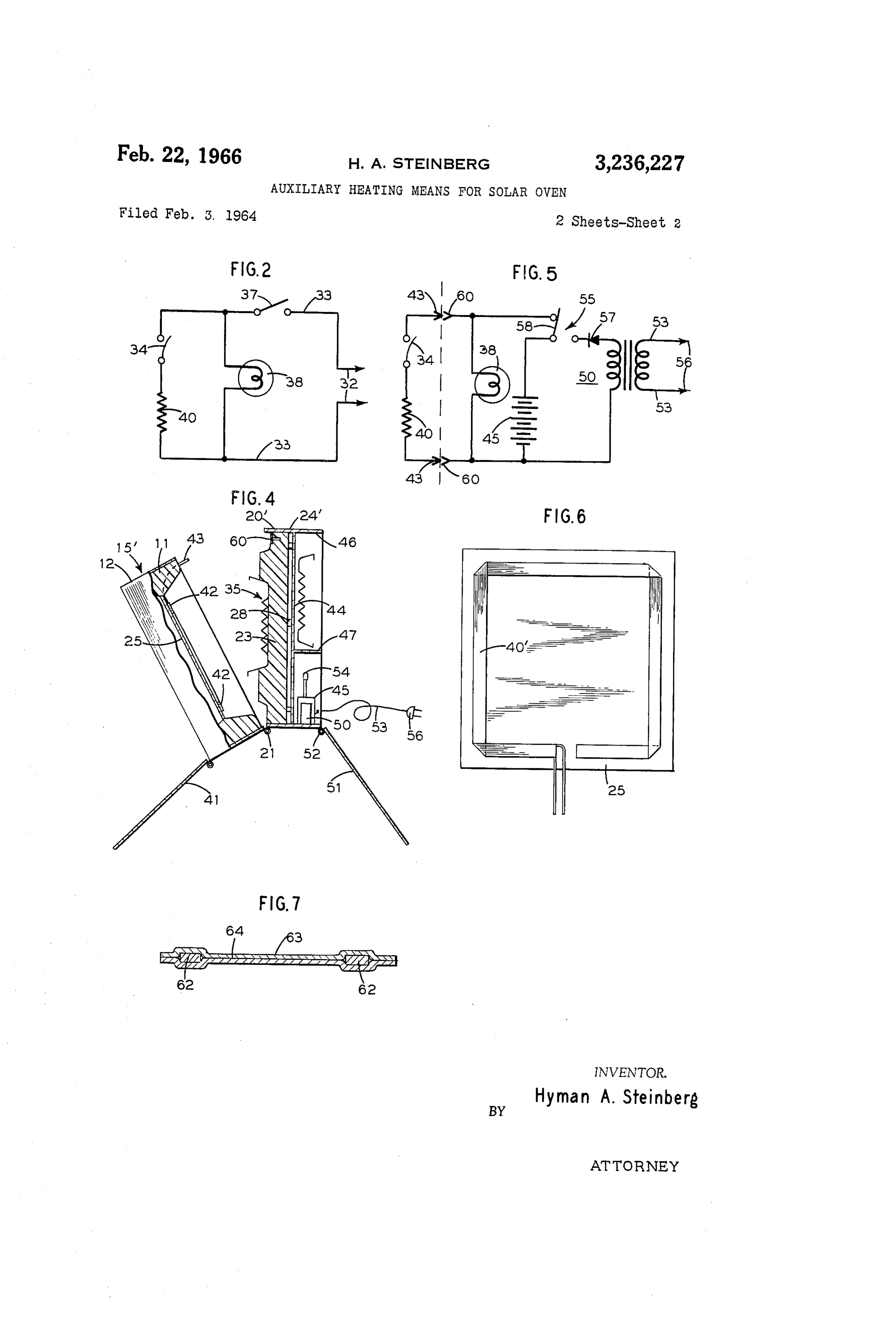
3,236,227 FIG. 5 is a schematic wiring diagram of the electric
AUXLIARY HEATING MEANS FOR SOLAR OVEN circuitry of the oven shown in FIGS. 3 and 4; Hyman A. Steinberg, 7-25 166th St., FIG. 6 is a bottom plan view of the grill illustrating a Whitestone 57, N.Y. preferred form of heating element thereon; and
Filed Feb. 3, 1964, Ser. No. 341,991 FIG. 7 is an enlarged and exaggerated cross section of 9 Claims. (C. 126-270) Such heating element.
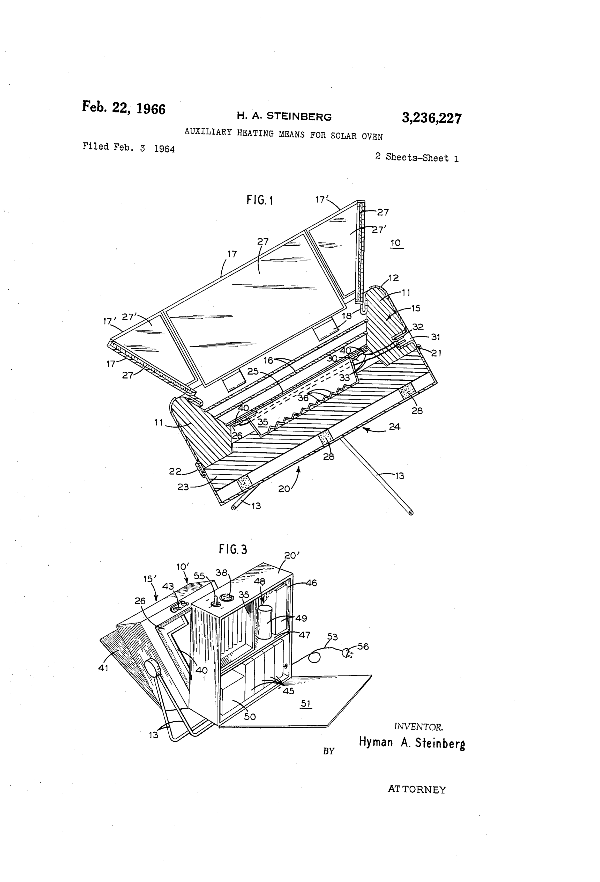
This invention relates to solar ovens and, more particu Referring particularly to FIG. 1, a typical, commer larly, to a solar oven provided with an auxiliary heating cially available solar oven, shown by way of example means whereby the oven may be used for heating and IO only, is indicated at 10 as including a body 15 and a door 20. Oven 10 is generally rectangular in plan, and body 15 cooking in the absence of solar energy.
Solar ovens essentially include a body formed with an comprises four side walls 11 of heat insulation material insulated heating compartment and a means for concen extending between the outer and inner end surfaces of the trating solar energy into the insulated heating compart body. These outer and inner end surfaces lie in substan ment to elevate the temperature thereof. In order to make 5 tially parallel planes perpendicular to the exterior surfaces the best available use of the solar energy, the heating of walls 11. The inner surfaces of sidewalls 1 of body compartment is very effectively insulated so that heat to15 define extend at an angle to the outer surfaces thereof so as an inwardly converging opening through body losses therefrom are kept to an absolute minimum. Thus, 15. In the particular oven selected by way of example, the heating compartment may be said to comprise a very efficient oven. 20 the inner surfaces of sidewalls 11 extend at an angle of However, solar ovens as hitherto constructed are useful substantially
60 with respect to the parallel end surfaces
The outer surfaces of the heat insulating only where there is available substantial solar energy, walls ill of body 15 are enclosed within a plastic, metal, as in the presence of bright or strong sunlight, for ex or wood casing generally ample, although the solar oven may be used with some 13 may be associated withindicated at 12. Support legs what less efficiency with relatively weak sunlight. In any 25 the same at a predetermined the oven, so as to maintain angle to the horizontal.
event, a solar oven is essentially a device for use only Door 20 is hinged to body 5 by hinge means indicated outdoors and only in the presence of sunlight. at 21, and may be retained in closed position by releas This factor, which is inherent in solar ovens as hitherto able latch means indicated at 22. Door 20 includes a constructed, has greatly reduced the use or availability body of heat insulation material 23 enclosed within a factor of these ovens, and the use factor is even further 30 pan-shape plastic, metal, or wood casing 24. Hinge means reduced in areas where sunlight is at a minimum. Never 21 and latch means 22 are on casings 12 and 24. Door theless, and due to the highly efficient heating compart 20 is arranged to close the inner end of body 5 and, in ment of solar ovens, it would be highly desirable that the closed position, to have the inner plane surface of the such solar ovens could be used indoors or when there is no sunlight. 35 heat insulation body 23 in substantial surface-to-surface It may further happen that the user of a solar oven contact with the inner plane end surface of body 15. may take the same to a picnic spot in anticipation of Sun At a short distance inwardly from the outer end Sur light and then find, when he arrives at the picnic area, en face of body 15, a pair of substantially parallel transpar that the sunlight has either disappeared or has been re 40 of walls plates 16 are mounted on ledges in the inner surfaces duced to a value insufficient for effective use of the solar 11, plates 16 preferably being in parallel relation oven. Consequently, if any picnic food is to be cooked, with each other and in sealing relation with the inner it must be cooked over an open fire or a fuel heated surfaces of walls 11 so as to define a substantially dead grill. airspace therebetween. Inwardly of the innermost plate An object of the present invention is to provide an im 16 there is a substantially flat grill 25 of heat absorbing and provement in solar ovens whereby the latter are not 45 heat may conductive material, such as a suitable metal which be blackened or otherwise treated so as to increase limited to use solely where there is available sunlight. its solar energy absorption. The inner surface of grill Another object of the invention is to provide a solar oven with auxiliary electric heating means for the heating 25 may be coated with a suitable plastic material 26 such as a fluorocarbon or silicone resin, to which food particles compartment.
Still another object of the invention is to provide a solar will not adhere and which is heat resistant. Grill 25 is
oven with auxiliary electric heating means which may be walls also supported in ledges in the inner surfaces of side energized from a rechargeable battery. 11 and is preferably in sealing relation with such Yet another object of the invention is to provide a solar inner surfaces so as to define a dead airspace between the oven with a hinged door forming one wall of the heating 55 innermost plate 16 and the grill 25. compartment, with this door having a compartment to re of Grill the 25 is spaced outwardly from the major portion inner surface of door 20, and the grill, conjointly ceive a rechargeable battery and/or a storage compart ment for food trays and other picnic items. with such inner surface of the door 20 and the portions These and other objects, advantages and novel features of sidewalls 11 inwardly of grill 25, defines a heating of the invention will be apparent from the following de 60 compartment 30. Heating compartment 30 is arranged scription of typical embodiments thereof as illustrated to receive a food pan or food chamber 35. In the em in the accompanying drawings. In the drawings: bodiment illustrated, food chamber 35 is substantially FIG. 1 is a transverse sectional view through one form rectangular in plan and somewhat smaller in area than of solar oven incorporating the improvement in accord grill 25. Food chamber or pan 35 has a bottom wall ance with the present invention; 65 arranged to rest on the inner surface of body 23 of cover FIG. 2 is a schematic wiring diagram of the electric 20, a pair of substantially parallel sidewalls, and a pair circuit of the solar oven shown in FIG. 1; of end walls.
FIG. 3 is a perspective view of another form of solar Pan or food chamber 35 may be formed in any suitable oven embodying the invention, the view illustrating the manner, from Suitable materials such as, for example, oven with the door and covers open; 70 aluminum foil, and the bottom wall of the pan may be FIG. 4 is a transverse sectional view of the oven shown formed with ribs 36 extending substantially parallel to in FIG. 3; the end walls of the pan. The upper edges of the end
Page 4
walls are formed with flat flanges, one directed inwardly wall of casing 12 and extending into the corresponding and the other directed outwardly, and these flanges are sidewall 1 of body 15, and a recessed type of male con arranged to lie in substantially planar contact with the nectors 32 is mounted in recess 31. A pair of leads or coating 26 of grill 25. To retain pan or food chamber insulated conductors 33 connect the prongs of male con 35 in a position, the inner surface of heat insulation nector 32 to electric resistance heating element 40. body 23 of door 20 may be formed with suitable retaining Thereby, oven 10 may be connected to a source of suitable means, illustrated in FIG. 1 as a substantially trapezoidal power by means of a utility cord of the type having a rib shaped to conform to the lower edges of the side and male cord plug on one end for engagement in a con end walls of pan 35 and to extend therearound. The venience outlet and a female connector on the opposite spacing of the inner surface of body 23 of door 20 from 10 end which will mate with male connector 32. For exam grill 25, in the closed position of door 20, is such that ple, the type of utility cord usually used to connect irons, the flanges on the end walls of pan 35 and the upper edges grills, cooking vessels, and the like, to a convenience of the sidewalls thereof are maintained in heat conducting outlet may be readily used with solar oven 10. contact with the inner surface coating 26 of grill 25. Referring to FIG. 2, heating element 40 is connected The open outer end of body 15 may be closed by a to conductors 33 in series with a suitable thermostat 34 plurality of walls 7 each hinged at its inner edge to Set to open, for example, at a maximum temperature of the inner surfaces of walls 11 of body 5, as indicated at 400 F. A single pole, single throw switch 37 is provided 18. In its open position, each wall 7 extends substan in one conductor 33 to control connection of element 40 tially parallel to the inner surface of its associated wall to male connector 32, and a suitable pilot lamp 38 may 1. The walls 7 may be made of any suitable rigid 20 be connected in parallel with the series combination of material, such as a plastic composition material, for heating element 40 and thermostat 34. Pilot lamp 38 example, and each wall has a mirror 27 on its inner will thus indicate when switch 37 is closed. surface. In order to form a completely mirrored, light With the provision of electric heating element 40 in entry tunnel for the solar oven in its operative position, heat conductive relation with grill 25, and the provision each hinged wall 17 has a trapezoidal corner wall 17' 25 of leads 33 and male connector 32, oven 10 may be hinged thereto, and each corner wall 17 has a mirror 27' readily connected to a convenience outlet for indoor use on its inner surface. or even to an Outdoor convenience outlet for outdoor use. The mirrored walls 7 and 17 are arranged to be However, the arrangement shown in FIGS. 1 and 2 has a folded, in substantially fiat overlapping relation, to close disadvantage that it can be used only where there is a the open outer end of body 15, and a suitable cover (not 30 Supply of commercial current available, with the use of shown) may be hinged to the outer end of body 15 to the Oven thus being limited to places which are accessi completely enclose the folded walls 7 and 57. When ble to power lines.
the solar oven is to be used, Walls 7 and 7 are unfolded The arrangement shown in FIGS. 3, 4 and 5 obviates so that each of the walls extends at an angle of Substan this limitation upon the use of solar oven 10. Referring tially 60° to the plane of grill 25, suitable means being 35 to these figures, the solar oven 10' illustrated therein, provided to maintain the walls in the erected position. insofar as its Solar heating function is concerned, is sub In operation, solar oven () is tilted in the direction of stantially identical with oven 0. Except for the location the sun, for example, to the position shown in FIG. 1. of a male connector, body 15 is identical with body 15 The Sun's rays pass through transparent plates 6 and and hence will not be described in detail. The afore impinge upon metal grill plate 25 which absorbs the solar 40 mentioned closure cover for the outer end of body 15, energy. Light entering into oven 0 is reflected by mir which may be closed after the mirrored walls are folded rors 27 and 27' in such a manner that all of the solar in overlapping relation, is indicated at 41 as hinged to energy is concentrated upon grill 25 so as to heat the casing 12 of body 15', Heating element 40, of which a heating compartment 30 containing food chamber or preferred form is described more fully hereinafter, is pan 35. 45 again engaged with the coated surface of grill 25, and When door 20 is swung open and food pan 35 is placed may be held thereagainst by a suitable heat resistant ad in position thereon, food may be placed in the pan and hesive tape 42. The opposite ends of heating element 40 the door may be closed so that the rim of the pan will are connected to the opposite terminals of a male con contact the inner coated surface of grill 25. In order ductor 43 which, in the arrangement shown in FIGS. 3 to assure a good sealing contact between body 15 and the 50 and 4, projects from the inner surface of sidewalls 11 of insulating body 23 of door 20, body 23 may be mounted to body 5.
float in the pan shape casing 24, as by being mounted Door 20' differs from door 20 in that it is provided upon Strips 28 of resilient material disposed on the inner with or formed with Suitable compartments for a re surface of the outer end wall of casing 24. These strips chargeable battery and a transformer, and/or for storage 28 may be strips or pieces of plastic or rubber foam of extra food chambers 35 and various picnic items. material. When door 20 is closed, the resiliency of the These compartments are formed by eXtending the side strips 28 and the floating mounting of body 23 in casing Walls of casing 24" outwardly beyond a transverse parti 24 assure a good tight seal between the inner Surface of tion 44 forming the Surface engaged by resilient strips 28 body 23 and the inner end surfaces of walls 1 of body 15.
In accordance with the invention, electric heating means 60 Walls areagainst bearing insulated body 23. The extended side indicated at 46. A partition or shelf 47 extends are provided within the heating compartment 30 of oven between a pair of opposite extended sidewalls 46 to divide 10. This electric heating means comprising a heating the aforementioned compartment in door 20' to provide element 40 which is mounted against the coated surface an upper Storage Space 48 arranged to receive extra food 26 of grill 25 around the outer periphery of chamber 35.
Element 40 may be in the form of an elongated strip of 65 chambers 35 as well as food and picnic items indicated high electrical resistance material which is held in contact generally at 49. Such items may include, for example, with surface 26 by a suitable heat resistant adhesive tape Salt, pepper and various condiments. Shelf 47 also forms or the like. However, a preferred form of heating ele a lower compartment which receives a multi-cell re ment is that shown in FIGS. 6 and 7 and which is a tape chargeable battery 45 and a transformer 50. A door 51 comprising a pair of laterally spaced copper conductors 70 is hinged at 52 to a sidewall extension 46 to close the sealed between Superposed strips of impregnated asbestos Compartment formed in door 20'.
with a conductive layer of graphite extending between the A utility cord 53 is connected to the input side of conductors. This element is described more fully here transformer 50 at a wiring junction 54. Cord 53 has a inafter. cord plug 56 at its outer end whereby the cord may be An outwardly opening recess 3i is formed in one side 75 plugged into any suitable convenience outlet.
Page 5
Referring to FIG. 5, a diode or rectifier 57 is connected tuted by a substantially flat metal plate of heat conducting in series between one secondary terminal of transformer and heat absorbing metal, and means for concentrating 50 and a contact of a control switch indicated at 55 and solar energy onto said plate to elevate the temperature of having a movable arm 58. Switch arm 58 is connected to said insulated heating compartment; the improvement one terminal of battery 45 and the opposite terminal of comprising an electric resistance heating element extend battery 45 is connected to the other terminal of the sec ing along the inner surface of said plate within said in ondary of transformer 50. Switch 55 is a single pole, Sulated heating compartment, an externally accessible double throw switch, and another fixed contact thereof is electrical connector, for connection to a source of electric connected to one side of a female connector 60 which is potential, and conductors connecting said heating ele mounted in a recess in the inner surface of insulating O ment to said connector.
body 23 of door 20' so as to engage male connector 43 4. In a solar oven, the improvement claimed in claim when door 20' is closed with relation to body 15'. The 3, including an adhesive tape of heat insulating material other side of female connector 60 is electrically connected covering said resistance heating element and securing the to that terminal of battery 45 which is connected directly same to said surface of said plate. to the secondary of transformer 50. Pilot light 38 is 5 5. In a solar oven comprising a body including an connected across female connector 60. In the position of insulated heating compartment and a means for con switch 55 shown in FiG. 5, battery 45 is connected in se centrating solar energy into said compartment to ele ries with heating element 40 and thermostat 34, and pilot vate the temperature thereof; the improvement com lamp 38 will be lit. When switch 55 is thrown to its other prising an electric heating element disposed within said position, and with cord plug 56 plugged into a con 20 insulated heating compartment, an externally accessible venience outlet, battery 45 will be recharged through first electrical connector on said body, for connection to diode 57. a source of electric potential, conductors connecting said As stated, the oven 10' of FIGS. 3, 4 and 5 is fully heating element to said connector, an insulated door portable and may be used where no commercial elec hinged to said body and defining a wall of said insulated tricity is available, by heating element 40 from battery 45. 25 compartment, a second electrical connector on said door Battery 45 may be conveniently recharged at any time by engageable with said first connector on closure of said moving switch 55 from the position shown on the draw door, a rechargeable battery mounted in said door, a ing to its other position. utility cord and plug extending from said door, and The type of compartmented door 20' of FIGS. 3 and switch means on said door electrically operable to con 4 may also be substituted for door 20 of oven 10 of 30 nect said battery to said second electrical connector, for FIG. 1. In such case, the compartments are used solely energizing said element, or to said cord, for recharging for storage of food and picnic items, as no battery is used said battery.
with oven 18 and no transformer is necessary. 6. In a solar oven, the improvement claimed in claim Referring to FIGS. 6 and 7, a preferred form of elec 5, in which the outer surface of the said door is formed tric resistance element 40' is illustrated as secured to grill as a compartment to receive said rechargeable battery, 25. Element 40', as best seen in FIG. 7, comprises a pair such compartment being subdivided to provide a storage of copper conductors 62 enclosed, in laterally spaced re space for food, food chambers and picnic items, and a lation, between impregnated asbestos strips 63. A layer cover hinged to said door to close said compartment of graphite 64 is also enclosed between strips 63 and in 40 therein.
electrical contact with conductors 62. At one end of ele 7. In a solar oven, the improvement claimed in claim ment 40', as viewed in FIG. 6, conductors 62 extend be 6, including a transformer in said door compartment, and yond strips 63 for connection to connector 32 or 43. having its primary winding connected to said utility cord While specific embodiments of the invention have been and its secondary winding connected to a rectifier means, shown and described in detail to illustrate the application said switch means having one position connecting said of the principles of the invention, it will be understood 45 battery to the secondary winding of said transformer that the invention may be embodied otherwise without through said rectifier means and a second position con departing from such principles. necting said battery to said second electrical connector. What is claimed is: 8. In a solar oven, the improvement claimed in claim 1. In a solar oven comprising a body including an in 50 3 in which said heating element comprises a pair of later Sulated heating compartment and means for concentrat ally spaced conductors enclosed between strips of heat ing solar energy into said compartment to elevate the resistant dielectric material and electrically intercon temperature thereof; the improvement comprising an elec nected by a layer of graphite between said strips and in tric heating element disposed within said insulated heat contact with said conductors.
ing compartment, an externally accessible electrical 9. In a solar oven, the improvement claimed in claim connector, for connection to a source of electric poten 3 including a door closing said heating compartment; the tial, and conductors connecting said heating element to outer surface of said door being as a storage compart said connector. ment, and a cover for said compartment. 2. In a solar oven comprising a body including an insu lated heating compartment, and means for concentrating 60 References Cited by the Examiner solar energy into said compartment to elevate the tem UNITED STATES PATENTS perature thereof; the improvement comprising an electric 412,725 10/1889 Calver ------------- 126-271 heating element disposed within said heating compart 681,095 8/1901 Baker ------------. 126-270 ment, an externally accessible electrical connector, for 1,074,219 9/1913 Skiff -------------- 126-270 connection to a source of electric potential, conductors 65 3,025,851 3/1962 Steinberg ----------- 126-270 connecting said heating element to said connector, and 3,106,201 10/1963 Steinberg ----------- 126-270 -a switch controlling connection of said heating element to said connector. FREDERICK L. MATTESON, JR., Primary Examiner. 3. In a solar oven comprising a body including an in JAMES W. WESTHAVER, Examiner.
sulated heating compartment having one wall consti O
Provenance
- Collection
- Cited prior art
- Original PDF
- patentimages.storage.googleapis.com →
- Filed
- 1964-02-03
- Pages
- 5
- Method
- pdftotext (the PDF's own text layer) + pdftoppm 300dpi page scans
- Source
- Google Patents bibliographic record
- Granted
- 1966-02-22
- Inventors
- Hyman A Steinberg
- Transcribed from
- patentimages.storage.googleapis.com →