patent · US3506554
Apparatus for separating electrophoretically active substances
14 April 1970
Page 1
Drawing sheet — no readable text.
Page 2
Drawing sheet — no readable text.
Page 3
United States Patent Office 3,506,554 Patented Apr. 14, 1970
3,506,554 The recovery of purified components from protein mix
APPARATUS FOR SEPARATING ELECTROPHO tures or other mixtures containing at least one electro RETICALLY ACTIVE SUBSTANCES phoretically active constituent may be effected by known John Broome, Philadelphia, Pa., assignor to processes involving, as a first step, processes similar to Samuel Raymond, Philadelphia, Pa. 5 the analytical process just described, conducted on either Continuation-in-part of application Ser. No. 546,102, a batchwise or continuous-flow basis. For example, paper Apr. 28, 1966. This application Mar. 15, 1968, Ser. electrophoresis may be carried out as a batch process and No. 715,485 separated components recovered by elution from selected Int. Cl, B01k 5/00 excised portions of the paper strip; or, in a known con
10 tinuous-flow process, the sample dissolved in the buffer may be continuously applied to a vertical, hanging sheet
ABSTRACT OF THE DISCLOSURE of paper and allowed to flow downwardly by gravity, A process and apparatus for separating electrophoretic while being subjected to a transverse electric field which causes the components to migrate transversely; the result ally active substances utilizes a continuously flowing 5 of the two simultaneous motions is that different compo stream of buffer to carry the substances through a Zone nents reach the bottom edge of the paper at different having an inert material which is permeable to either the places where they may be separately collected. electrophoretically active material or small buffer ions. There are other electrophoretic processes presently An electric field is applied first in one direction and then known in the art which are more or less similar to those in a changed direction so that at least some of the elec 20 described above. It is characteristic of all known electro trophoretically migrating components migrate into the in phoresis processes that they all use direct current con ert material leaving other components in the stream, and tinuously applied in one direction only in order to effect when the direction of the electric field is changed, the electrophoretic migration of the components as desired, electrophoretically migrating components migrate back although the direct current may be furnished by a power into the stream so that at least electrophoretically active 25 supply and obtained by converting alternating current. It components are separated first. The cycle of reversing is also characteristic of known electrophoresis processes the direction of the electric field is repeated many times. that components of lower electrophoretic mobility move Preferably the inert immobile material is in the form of more slowly and are not separated as effectively as com a matrix having interstices through which the buffer flows, ponents of higher electrophoretic mobility. although it could be a gel slab at one side of the buffer 30 The known electrophoretic processes leave much room stream. Preferably the reversing field is applied from any for improvement in certain respects, such as resolving direction although it could, with the gel slab arrange power, rapidity of operation, sensitivity of detection, dilu ment, be applied from opposite sides of the fixed gel slab. tion of components and adaptability to various supporting media.
CROSS REFERENCE TO RELATED SUMMARY OF THE INVENTION
APPLICATIONS This invention provides an electrophoresis process and This application is a continuation-in-part of prior ap apparatus which will increase the sensitivity of detec plication Ser. No. 546,102, filed Apr 28, 1966, now aban 40 tion of individual components, shorten the time required doned, titled “Process and Apparatus for Electrophoretic for both preparative and analytic processes, improve the resolution of closely related components and permit the
Separation,” inventor John Broome assignor to Samuel detection and recovery of components of very low or Raymond. even zero electrophoretic mobility. BACKGROUND OF INVENTION The process of this invention includes flowing a stream 45 of buffer through a zone having an immobile matrix
Field of invention which is permeable to electrophoretic materials to be This invention relates to improvements in process and separated, injecting a mixture sample containing at least apparatus for separating electrophoretically active Sub some electrophoretically active material into the flowing Stances.
buffer stream, applying an electric field in a direction to
Prior art cause a portion of the mixture having faster electro phoretically migrating components to migrate into the im
Mixtures of electrophoretically active substances, such mobile matrix leaving a portion of the mixture having as proteins, have heretofore been separated by various slower electrophoretically migrating components in the known processes of electrophoresis. For example, to ana flowing buffer stream, and after the stream has contin lyze a protein mixture by paper electrophoresis, a strip 55 ued to flow so that the two components are further sepa of suitable paper is wetted with a buffer solution; a sam rated then reversing the direction of electric field so that ple of proteins dissolved in buffer solution is placed on the faster migrating components are returned to the flow the paper; a current of electricity is passed along the ing stream. The field reversal and stream flow are re paper in one direction from one end to the other, so that 60 peated, either successively or simultaneously, as many an electric field is maintained in the paper strip, the pro times as necessary to achieve the desired degree of sepa tein components migrate along the paper strip in a direc ration of the components in the mixture sample. tion parallel to the electric field at migration rates char In a preferred embodiment the immobile matrix is po acteristic of each specific protein component; thus, each sitioned in the path of the flowing stream of the buffer specific component migrates to a specific location along and has interstices through which the buffer flows, and in the strip in a predetermined time thereby becoming sepa 65 this embodiment the electric field may be applied at any rated from the others; and the specific components so angle to the direction of flow of the buffer. In another separated are located and quantitated by colorimetric or embodiment the immobile matrix is in the form of slabs other means. To improve the resolution of the analysis and the electric field is applied at a direction transverse various other known supporting media have been em 70 to the flow of the buffer adjacent a surface of the slab. ployed, for example, a slab of polyacrylamide gel has Thus, it is the fundamental concept of this invention been used as supporting media. to remove and then replace electrophoretically active
Page 4
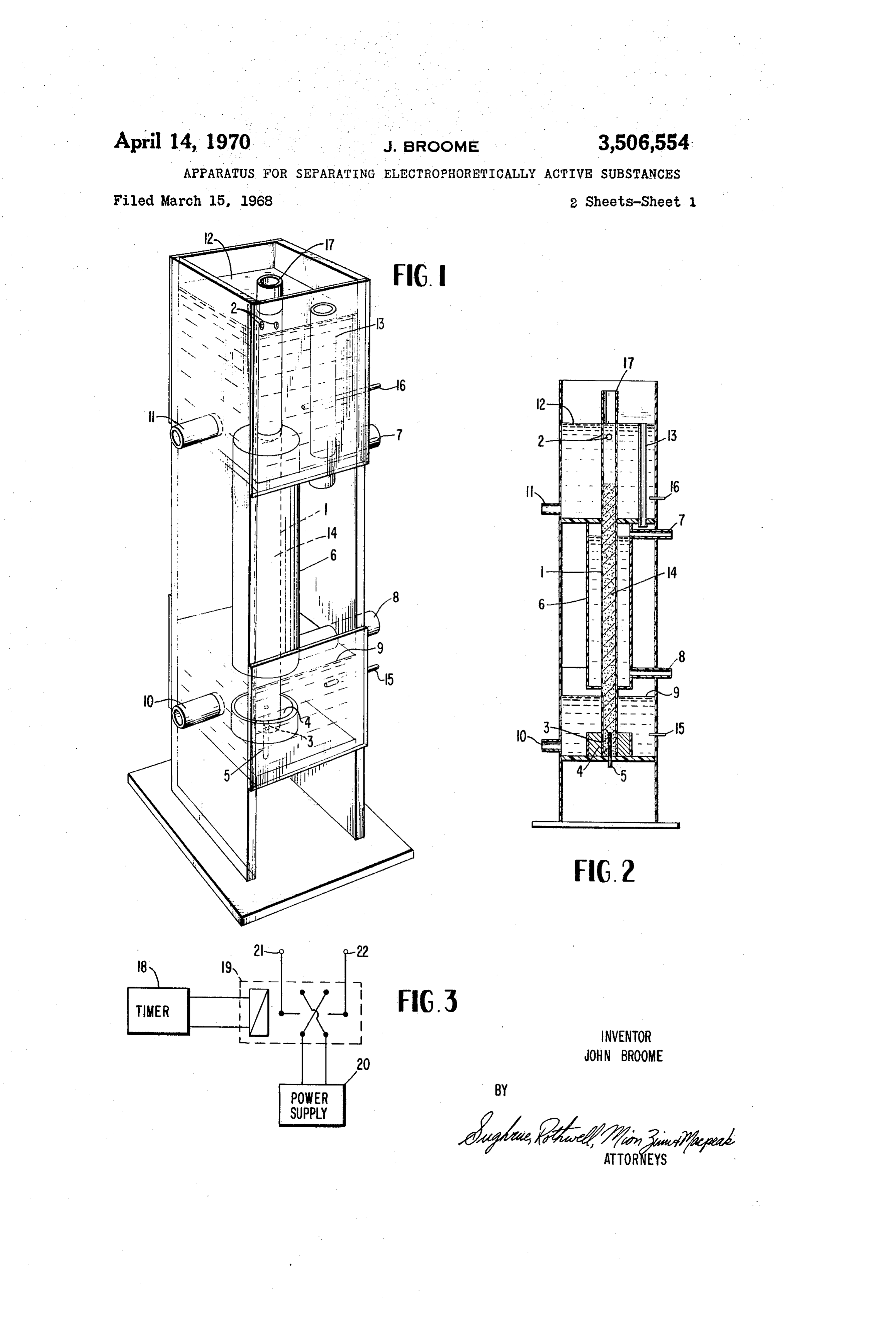
components of substances in a flowing buffer stream by With the apparatus of FIGS. 1-3 it is convenient for alternately reversing an applied electric field. the field to be applied along the axis of the column. How The apparatus of this invention for carrying out the ever, this is not essential since separation is obtained process includes electrically non-conducting supporting with any orientation of the alternating field with respect and containing members and chambers for the flowing to the axis of flow. In the FIGS. 4 and 5 embodiment the stream of buffer immobile matrix, and conductive elec 5 reversing field is set perpendicular to the flow of buffer trodes through which the reversing electric field is applied. as this is advantageous with a preparative scale instru BRIEF DESCRIPTION OF THE DRAWINGS ment since the temperature may be more readily con trolled through the larger surface area per unit volume
The invention will be described by way of example in of a column with rectangular cross section. connection with the accompanying drawings in which: 10 Referring specifically to FIGS. 1 and 2, a column 1 of FIG. 1 is a perspective view of a preferred form of electrically insulating material contains semi-permeable electrophoretic apparatus for practicing the process of granular packing 14 supported vertically which forms the this invention. inert matrix and provides interstitial spaces between the FIG. 2 is a schematic longitudinal cross sectional eleva granules. The upper end of the packing 14 communi tion view of the apparatus shown in FIG. 1. cates with an upper buffer reservoir 12 via openings 2 and FIG. 3 is a schematic circuit diagram of a power sup this upper reservoir is filled with an electrically conduct ply for supplying the reversing electric field. ing buffer liquid.
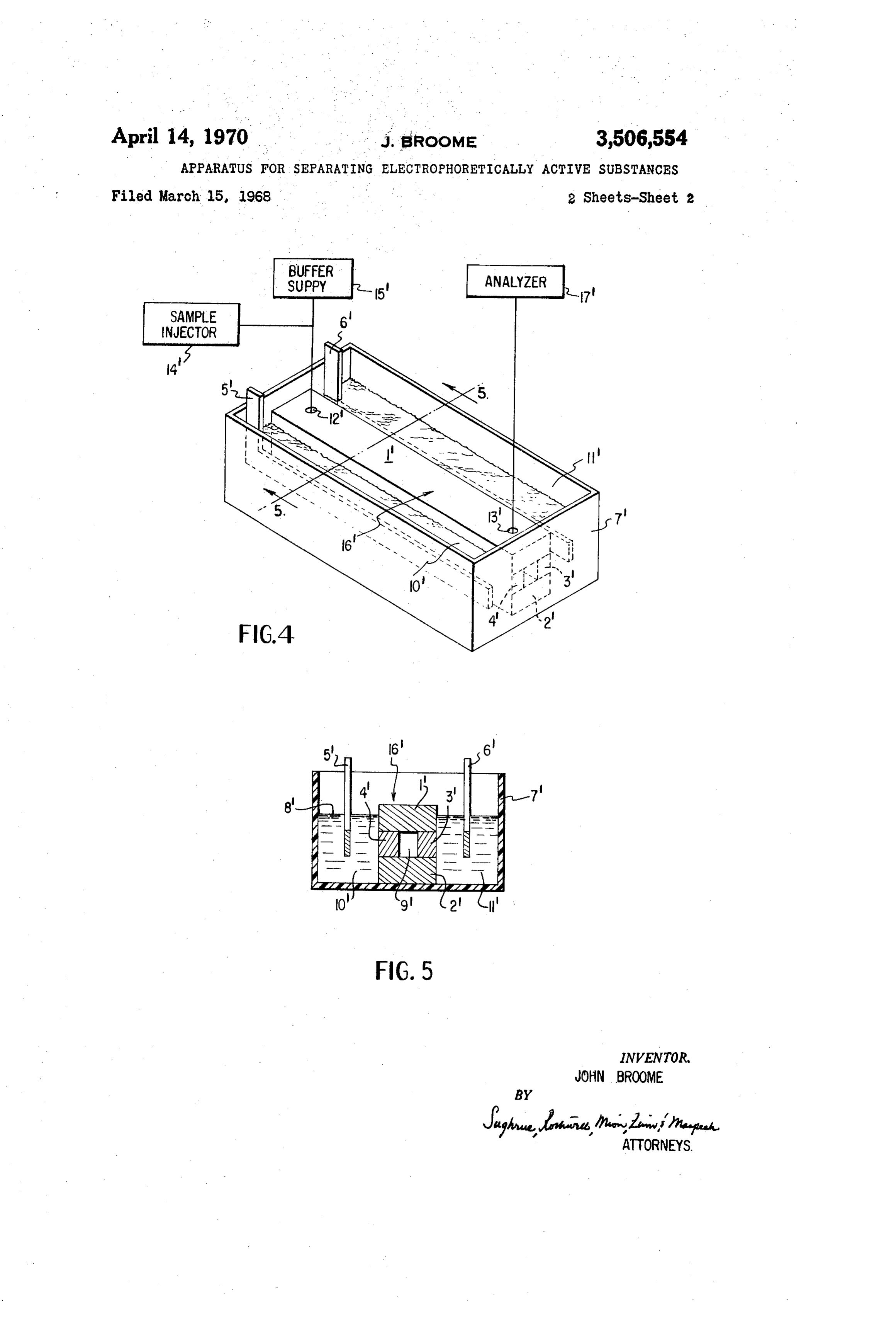
FIG. 4 is a perspective view of a modified electro The lower end of packing 14 is in fluid communica phoresis apparatus within the scope of this invention. 20 tion with a lower buffer reservoir 9 through openings 3 FIG. 5 is a sectional elevation taken along line 5-5 of which, however, are filled with an electrically conducting FIG. 4. semi-permeable gel 4. The lower end of column 1 is pro DESCRIPTION OF PREFERRED EMBODIMENTS vided with a liquid effluent connection 5. For cooling, a cooling jacket 6 receives a supply of
FIGS. 1-3 illustrate the preferred embodiment of the 25 liquid coolant through inlet and outlet connections 7 and process and apparatus of the invention in which a flow 8. Electrophoretic buffer is pumped from lower reservoir ing buffer stream passes through interstices of an im 9 through outlet port 10 to a buffer inlet 11 of the upper mobile matrix which is at least partially permeable to buffer reservoir 12. The buffer liquid is pumped at such electrophoretic materials to be separated, and a mixture a rate that excess is returned to the lower tank by means sample containing at least some electrophoretically active 30 of an overflow tube 13. This arrangement ensures that materials injected into the flowing buffer stream. An elec the granular packing 14 experiences a constant head of tric field can be applied at any angle to the direction of buffer.
flow when the buffer passes through the interstices of Voltage is supplied to two electrodes 15 and 16. A the matrix so that a portion of the mixture enriched in sample containing at least some electrophoretically active faster electrophoretically migrating components migrates components may be conveniently pipetted into the granu to the immobile matrix leaving a portion of the mixture, lar packing 14 through an open top 17 of column 1. enriched in slower electrophoretically migrating compo FIG. 3 is a circuit diagram of a suitable power supply nents in the flowing buffer stream. While the stream is which per se forms no part of this invention. Any device flowing further the direction of the electric field is re 40 capable of providing an alternating voltage with periods versed returning the faster migrating components to the in the range of 0.2 to 0.02 Hz. can be employed. As buffer stream. This field reversal may be continued as shown in FIG. 3 a simple power supply includes a revers many times as necessary to achieve the desired degree of ing relay 19 driven by a repeating timer 18. Voltage is separation of components. supplied to the relay from a DC supply 20, typically 500 This process permits a substantial degree of freedom volts. The output side of the relay is connected to the from the limitations inherent in electrophoretic tech 45 cell electrode 16 via suitable interconnections 21 and 22. niques previously known. This follows from the fact that The buffer of this invention may be defined as a fluid physical transport is no longer effected exclusively by capable of dissolving the desired components of the elec electrophoresis, but the electrophoretic parameters con trophoretically active mixture and substantially maintain trol the partition of the sample components between a ing their electrophoretic properties constant during the stationary matrix and flowing stream, while actual trans separation.
port of the components is carried out by the flowing The mixture separated will be referred to as a protein stream. Thus the least electrophoretically active materials mixture although understood that mixtures containing will be the first transported out by the flowing stream. other electrophoretically active substance can also be sep FIGS. 1-3 illustrate one suitable apparatus for accom arated in accordance with the invention. plishing this type of separation. The apparatus includes a 5 5 In practicing the preferred embodiment of this inven column with walls of inert electrically insulating material tion shown in FIGS. 1-3, the tanks 9 and 12 are filled with filled with a slurry of granules which constitute the matrix the buffer solution which is continuously circulated by having interstices through which a buffer can flow. The pumping from the lower reservoir 9 to the upper reser buffer liquid forms a continuous phase in the interstices voir 12 via pumping fluid lines (not shown). The efflu between the granules. It is preferred to use granules which 60 ent connection or outlet 5 is connected to a recording are semi-permeable, i.e., which permit small molecules analyzer, such as a recording spectrophotometer set to and ions to pass freely through their interior, but which record at a wavelength within the absorption band of a restrict or impede to a degree the entry of desired com protein. Electrodes 15 and 16 are connected to a source ponents of the sample. Hence the sample is normally con of DC electrical power which includes means for re fined to the interstitial spaces. If an electric field is ap 65 versing the polarity of the electrodes periodically such plied across such system, some components of the sample as the arrangement in FIG. 3. The periodicity of the will enter the granules. Components entering the interior reversing may range from a few cycles per second up of a granule may be recovered into the interstices in the to a few cycles per hour, depending upon the electro flowing buffer stream either by electromigration entirely phoretic mobility of the protein to be separated. With through the granule, by diffusion therefrom, or by revers a constant stream of buffer flowing through column 1 ing the electric field. The flow of buffer through the and through the interstices of the granules 14 therein, column carries with it the desired components through a suitable pre-run period is employed to make sure that the column although each component is retarded to some the apparatus is in stable dynamic equilibrium and that extent in proportion to the time spent within the station a stable base line is obtained. Then a volume of sample ary matriX. is pipetted onto the column bed or granules 14 through
Page 5
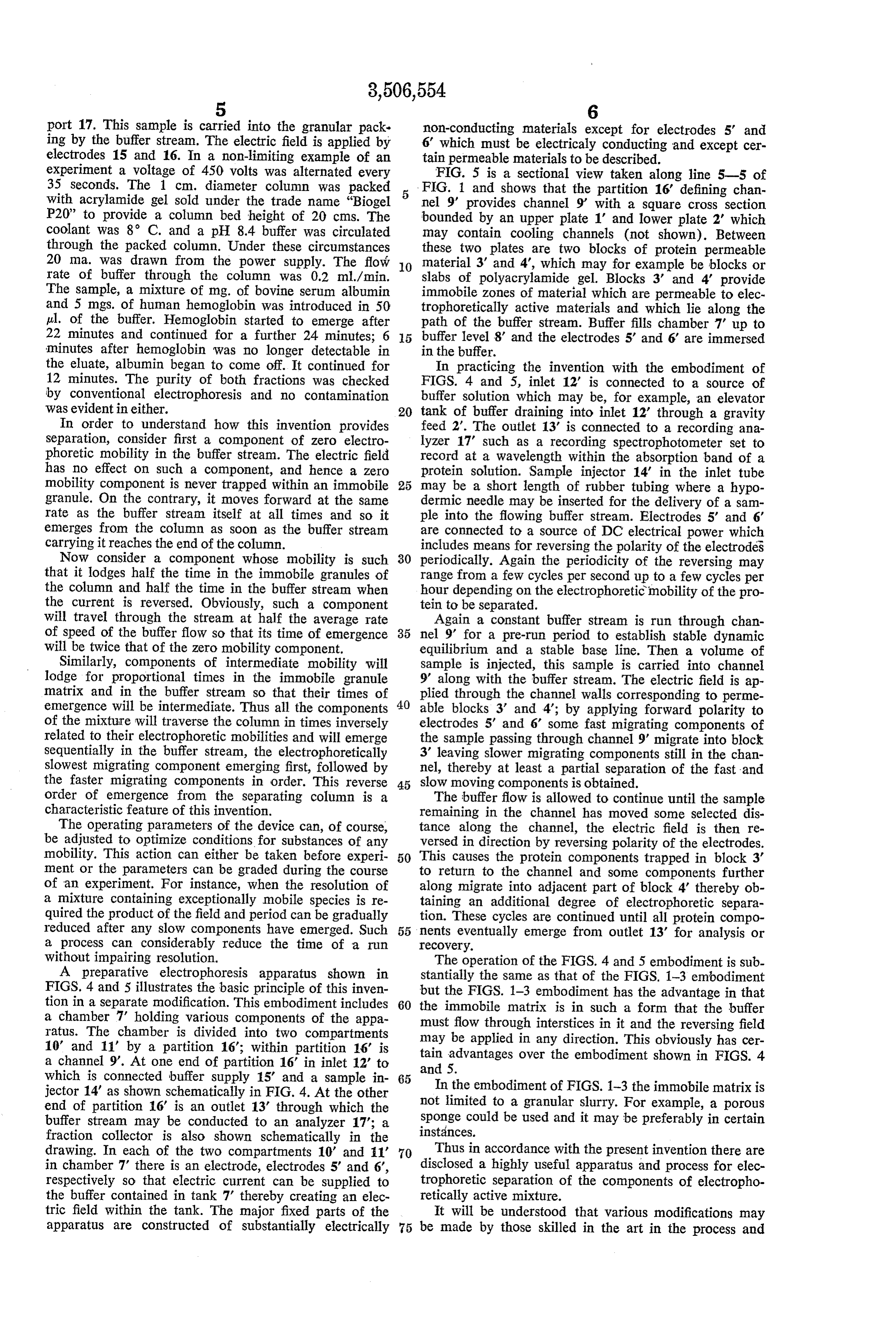
port 17. This sample is carried into the granular pack non-conducting materials except for electrodes 5' and ing by the buffer stream. The electric field is applied by 6' which must be electrically conducting and except cer electrodes 15 and 16. In a non-limiting example of an tain permeable materials to be described. experiment a voltage of 450 volts was alternated every FIG. 5 is a sectional view taken along line 5-5 of 35 seconds. The 1 cm. diameter column was packed FIG. 1 and shows that the partition 16 defining chan with acrylamide gel sold under the trade name "Biogel nel 9' provides channel 9' with a square cross section P20' to provide a column bed height of 20 cms. The bounded by an upper plate 1 and lower plate 2' which coolant was 8 C. and a pH 8.4 buffer was circulated may contain cooling channels (not shown). Between through the packed column. Under these circumstances these two plates are two blocks of protein permeable 20 ma. was drawn from the power supply. The flow 10 material 3' and 4, which may for example be blocks or rate of buffer through the column was 0.2 ml./min. slabs of polyacrylamide gel. Blocks 3' and 4 provide The sample, a mixture of mg. of bovine serum albumin immobile zones of material which are permeable to elec and 5 mgs. of human hemoglobin was introduced in 50 trophoretically active materials and which lie along the pl. of the buffer. Hemoglobin started to emerge after path of the buffer stream. Buffer fills chamber 7' up to 22 minutes and continued for a further 24 minutes; 6 buffer level 8' and the electrodes 5' and 6 are immersed minutes after hemoglobin was no longer detectable in in the buffer.
the eluate, albumin began to come off. It continued for In practicing the invention with the embodiment of 12 minutes. The purity of both fractions was checked FIGS. 4 and 5, inlet 12' is connected to a source of by conventional electrophoresis and no contamination buffer solution which may be, for example, an elevator was evident in either. 20 tank of buffer draining into inlet 12 through a gravity In order to understand how this invention provides feed 2'. The outlet 13' is connected to a recording ana separation, consider first a component of zero electro lyzer 17' such as a recording spectrophotometer set to phoretic mobility in the buffer stream. The electric field record at a wavelength within the absorption band of a has no effect on such a component, and hence a zero protein solution. Sample injector 14 in the inlet tube mobility component is never trapped within an immobile 25 may be a short length of rubber tubing where a hypo granule. On the contrary, it moves forward at the same dermic needle may be inserted for the delivery of a sam rate as the buffer stream itself at all times and so it ple into the flowing buffer stream. Electrodes 5' and 6' emerges from the column as soon as the buffer stream are connected to a source of DC electrical power which carrying it reaches the end of the column. includes means for reversing the polarity of the electrodes Now consider a component whose mobility is such 30 periodically. Again the periodicity of the reversing may that it lodges half the time in the immobile granules of range from a few cycles per second up to a few cycles per the column and half the time in the buffer stream when hour depending on the electrophoretic mobility of the pro the current is reversed. Obviously, such a component tein to be separated.
will travel through the stream at half the average rate Again a constant buffer stream is run through chan of speed of the buffer flow so that its time of emergence nel 9' for a pre-run period to establish stable dynamic will be twice that of the zero mobility component. equilibrium and a stable base line. Then a volume of Similarly, components of intermediate mobility will sample is injected, this sample is carried into channel lodge for proportional times in the immobile granule 9 along with the buffer stream. The electric field is ap matrix and in the buffer stream so that their times of plied through the channel walls corresponding to perme emergence will be intermediate. Thus all the components 40 able blocks 3' and 4'; by applying forward polarity to of the mixture will traverse the column in times inversely electrodes 5' and 6 some fast migrating components of related to their electrophoretic mobilities and will emerge the sample passing through channel 9' migrate into block sequentially in the buffer stream, the electrophoretically 3' leaving slower migrating components still in the chan slowest migrating component emerging first, followed by nel, thereby at least a partial separation of the fast and the faster migrating components in order. This reverse 45 slow moving components is obtained. order of emergence from the separating column is a The buffer flow is allowed to continue until the sample characteristic feature of this invention. remaining in the channel has moved some selected dis The operating parameters of the device can, of course, tance along the channel, the electric field is then re be adjusted to optimize conditions for substances of any versed in direction by reversing polarity of the electrodes. mobility. This action can either be taken before experi 50 This causes the protein components trapped in block 3 ment or the parameters can be graded during the course to return to the channel and some components further of an experiment. For instance, when the resolution of along migrate into adjacent part of block 4 thereby ob a mixture containing exceptionally mobile species is re taining an additional degree of electrophoretic separa quired the product of the field and period can be gradually tion. These cycles are continued until all protein compo reduced after any slow components have emerged. Such 55 nents eventually emerge from outlet 13' for analysis or a process can considerably reduce the time of a run recovery.
without impairing resolution. The operation of the FIGS. 4 and 5 embodiment is sub A preparative electrophoresis apparatus shown in stantially the same as that of the FIGS. 1-3 embodiment FIGS. 4 and 5 illustrates the basic principle of this inven but the FIGS. 1-3 embodiment has the advantage in that tion in a separate modification. This embodiment includes 60 the immobile matrix is in such a form that the buffer a chamber 7 holding various components of the appa must flow through interstices in it and the reversing field ratus. The chamber is divided into two compartments may be applied in any direction. This obviously has cer 10' and 11" by a partition 16; within partition 16' is tain advantages over the embodiment shown in FIGS. 4 a channel 9'. At one end of partition 16' in inlet 12' to which is connected buffer supply 15' and a sample in 65 andIn5.the embodiment of FIGS. 1-3 the immobile matrix is jector 14' as shown schematically in FIG. 4. At the other not limited to a granular slurry. For example, a porous end of partition 16' is an outlet 13 through which the buffer stream may be conducted to an analyzer 17'; a instances.sponge could be used and it may be preferably in certain fraction collector is also shown schematically in the drawing. In each of the two compartments 10' and 1 70 Thus in accordance with the present invention there are in chamber 7 there is an electrode, electrodes 5' and 6', disclosed a highly useful apparatus and process for elec respectively so that electric current can be supplied to trophoretic separation of the components of electropho the buffer contained in tank 7 thereby creating an elec retically active mixture.
tric field within the tank. The major fixed parts of the It will be understood that various modifications may apparatus are constructed of substantially electrically 75 be made by those skilled in the art in the process and
Page 6
apparatus described herein by way of illustration without stantial separation of the components of the mixture is departing from the spirit of the invention as defined in the effected.
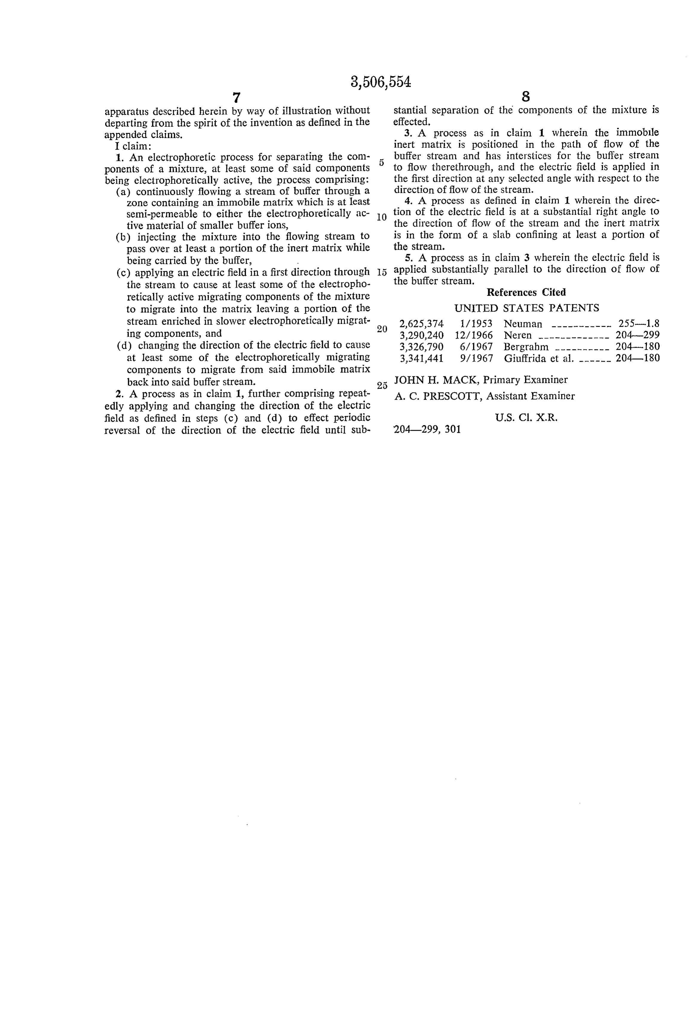
appended claims. 3. A process as in claim 1 wherein the immobile I claim: inert matrix is positioned in the path of flow of the 1. An electrophoretic process for separating the com buffer stream and has interstices for the buffer stream ponents of a mixture, at least some of said components 5 to flow therethrough, and the electric field is applied in being electrophoretically active, the process comprising: the first direction at any selected angle with respect to the (a) continuously flowing a stream of buffer through a direction of flow of the stream. zone containing an immobile matrix which is at least 4. A process as defined in claim 1 wherein the direc semi-permeable to either the electrophoretically ac 10 tion of the electric field is at a substantial right angle to tive material of smaller buffer ions, the direction of flow of the stream and the inert matrix (b) injecting the mixture into the flowing stream to is in the form of a slab confining at least a portion of pass over at least a portion of the inert matrix while the stream.
being carried by the buffer, 5. A process as in claim 3 wherein the electric field is (c) applying an electric field in a first direction through applied substantially parallel to the direction of flow of the stream to cause at least some of the electropho the buffer stream.
retically active migrating components of the mixture References Cited to migrate into the matrix leaving a portion of the UNITED STATES PATENTS stream enriched in slower electrophoretically migrat 20 2,625,374 1/1953 Neuman ––––------- 255-1.8 ing components, and 3,290,240 12/1966 Neren ——————————— 204-299 (d) changing the direction of the electric field to cause 3,326,790 6/1967 Bergrahim -------- 204-180 at least some of the electrophoretically migrating 3,341,441 9/1967 Giuffrida et al. ----- 204-180 components to migrate from said immobile matrix back into said buffer stream. JOHN H. MACK, Primary Examiner 2. A process as in claim 1, further comprising repeat A. C. PRESCOTT, Assistant Examiner edly applying and changing the direction of the electric field as defined in steps (c) and (d) to effect periodic U.S. C1. X.R., reversal of the direction of the electric field until sub 204299, 301
Page 7
UNITED STATES PATENT OFFICE
CERTIFICATE OF CORRECTION
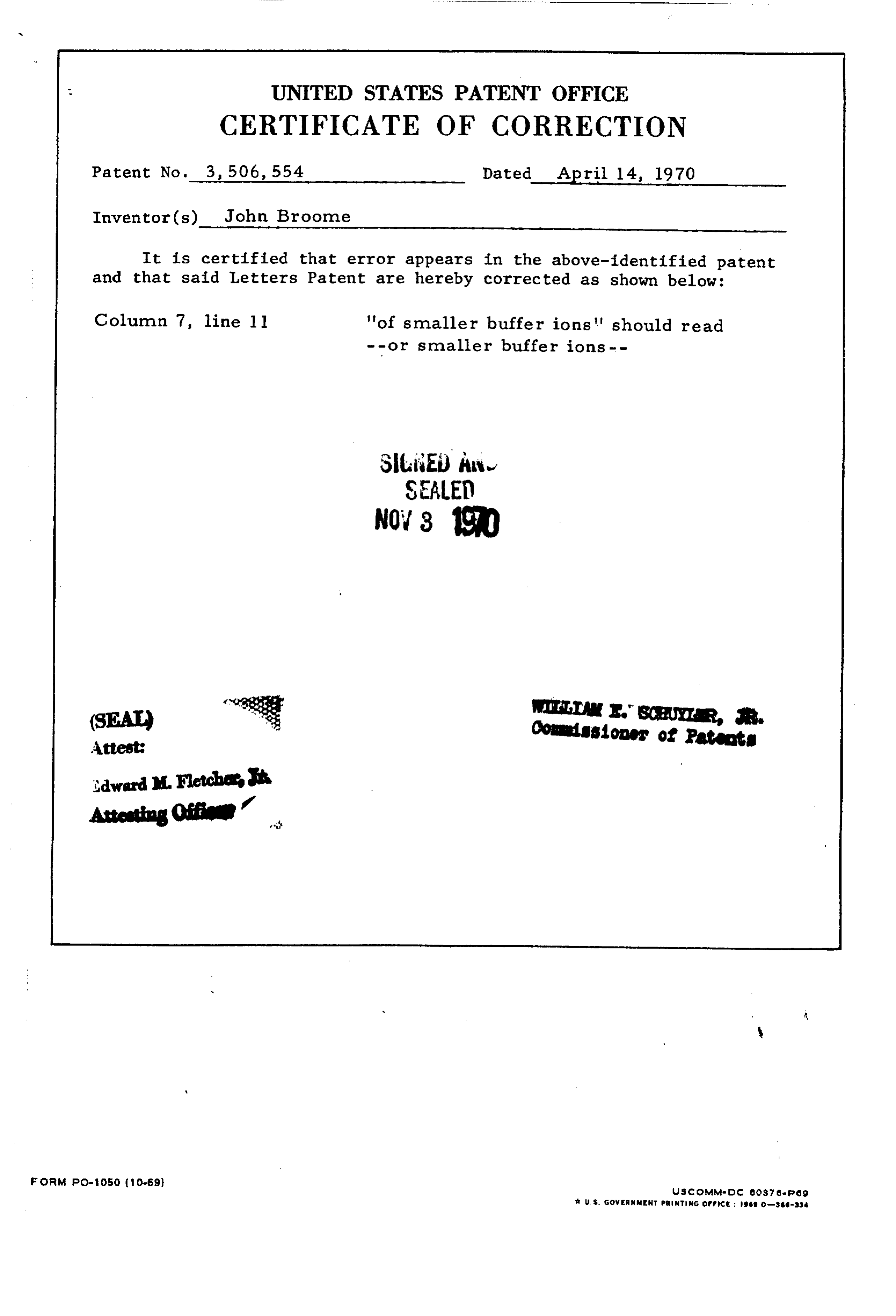
Patent No. 3, 506, 554 Dated April 14, 1970 Inventor(s) John Broone
It is certified that error appears in the above-identified patent and that said Letters Patent are hereby corrected as shown below: Column 7, line ll 'of smaller buffer ions' should read -- or smaller buffer ions--
SitiEi) èw
SEALE
Arse R.
Conissioner of Patantg
FORM PO-1050 (10-69) USCOMMsid C. CO37 speg U.S. Gover NMENT PRNTING OFFIce : geo-sss-ssa
Provenance
- Collection
- Cited prior art
- Original PDF
- patentimages.storage.googleapis.com →
- Filed
- 1968-03-15
- Pages
- 7
- Method
- pdftotext (the PDF's own text layer) + pdftoppm 300dpi page scans
- Source
- Google Patents bibliographic record
- Granted
- 1970-04-14
- Inventors
- John Broome
- Transcribed from
- patentimages.storage.googleapis.com →