patent · US4126435
Apparatus for removing finely divided solids from gas
21 November 1978
Page 1 — bibliographic record
United States Patent (19) (11) 4,126,435 Reese 45) Nov. 21, 1978 54 APPARATUS FOR REMOVING FINELY Attorney, Agent, or Firm-Limbach, Limbach & Sutton DIVIDED SOLIDS FROM GAS (57) ABSTRACT 75) Inventor: Richard G. Reese, Woodside, Calif. Apparatus for separating finely divided solids from gas 73 Assignee: Combustion Power Company, Inc., is described comprising a generally cylindrical vessel Menlo Park, Calif. having a gas inlet opening and a gas outlet opening, a solids inlet opening at the top of the vessel and a solids (21) Appl. No.: 722,559 outlet opening at the bottom of the vessel. First gener (22 Filed: Sep. 13, 1976 ally cylindrical wall member having a diameter less than that of the vessel is disposed in the vessel to pro
Related U.S. Application Data vide an elongated annular space lying between it and 63 Continuation-in-part of Ser. No. 510,291, Sep. 30, 1974, the vessel wall. The first cylindrical wall member is in Pat. No. 4,017,278. sealing engagement with the top portion of the vessel. A second generally cylindrical wall member having a 51 Int. C.’.............................................. B01D 46/34 diameter less than the first wall member is disposed 52 U.S.C. ......................................... 55/474;55/518 inside the first wall member to provide an elongated 58) Field of Search ..................... 55/98, 99, 329, 330, annular space between the two wall members which 55/474,479,512,515,518,390;34/174; 23/288 space is filled with a solid particulate contact material G, 288 K and which moves by gravity flow downwardly through (56) References Cited the annular space. The surfaces of both cylindrical wall
the walls to form louver vanes inclined to the vertical at 1,570,869 1/1926 Thomson et al. ........................ 55/99 an angle of about 15 to 80 and having louver openings 1,871,166 8/1932 Fahrbach ............................... 55/512 sufficiently large that most of the particles constituting 1,995,292 3/1935 Clark ...................................... 55/474 the contact mass are capable of passing through the 2,488,493 11/1949 Evans ..................................... 55/474 openings. The louver vanes of the first cylindrical wall 3,652,231 3/1972 Greenwood et al. . 23/288 G 3,800,508 4/1974 Zenz ....................................... 55/479 member extend outwardly and those of the second wall 3,920,427 11/1975 Lachnit .................................. 55/479 member extend inwardly. Means for controlling the 3,982,326 9/1976 Squires ................................... 55/479 flow of the solid contact material through the louver
FOREIGN PATENT DOCUMENTS
openings to restrict the flow to a minor proportion of the total contact material and means for facilitating 794,042 2/1936 France ....................................... 55/479 passage of the overflow contact material through a 877,536 12/1942 France ....................................... 55/515 solids outlet opening in the bottom of the vessel are 1,497,602 10/1967 France ....................................... 34/174 provided.
Primary Examiner-Frank w. Lutter 4 Claims, 8 Drawing Figures Assistant Examiner-David L. Lacey
Page 2
Drawing sheet — no readable text.
Page 3
Drawing sheet — no readable text.
Page 4
Drawing sheet — no readable text.
Page 5
closes the top of annular space 7 against inflow of par
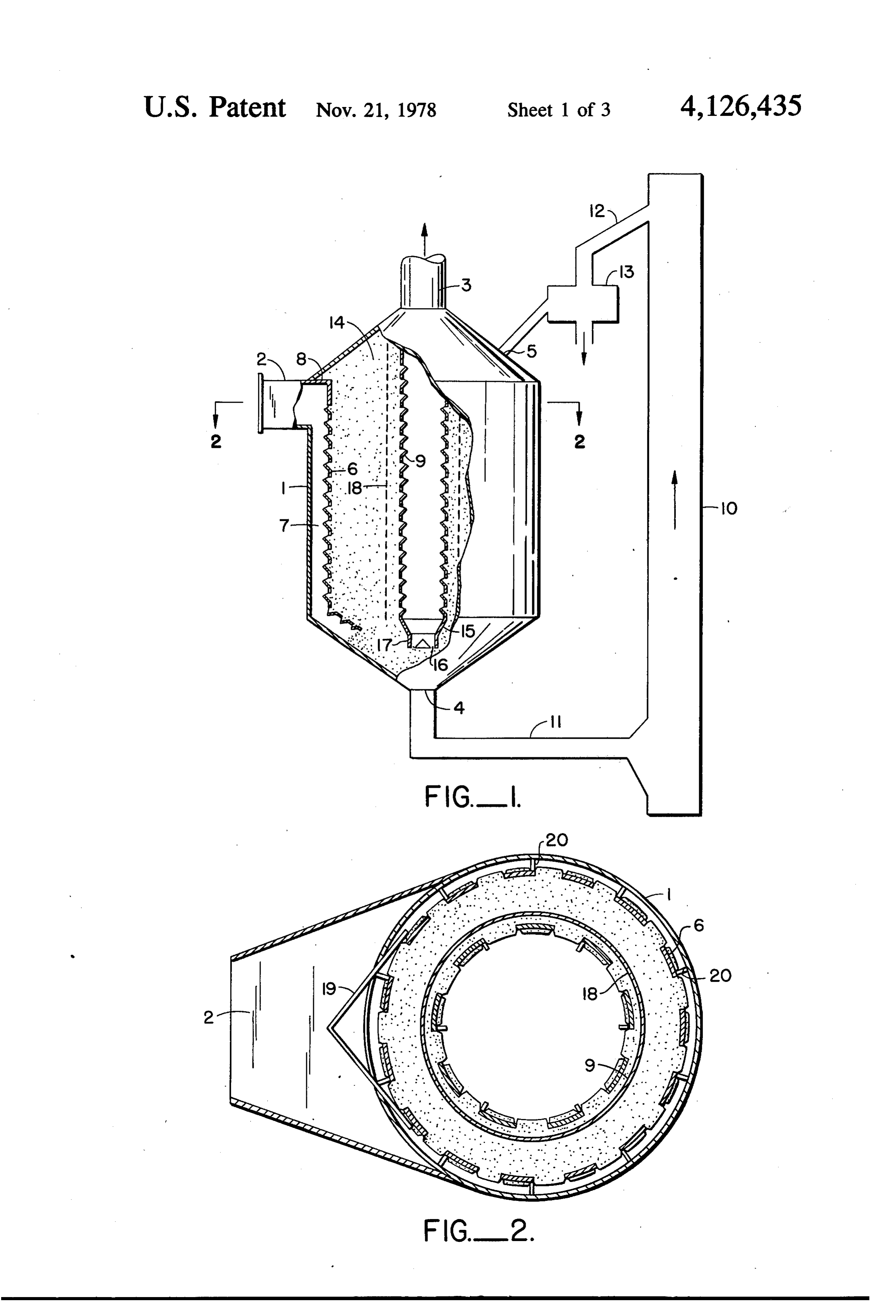
APPARATUS FOR REMOVING FINELY DIVIDED ticulate solid material 14. Annular space 7 is open at its SOLIDS FROM GAS bottom communicating with the frusto-conical bottom This application is a continuation-in-part of applica of vessel 1. A second cylindrical wall member 9 having tion Ser. No. 510,291 filed Sept. 30, 1974, now U.S. Pat. 5 a diameter smaller than that of first cylindrical wall No. 4,017,278, for METHOD AND APPARATUS member 6 and having a louvered surface is concentri FOR REMOVING FINELY DIVIDED SOLIDS cally disposed in first cylindrical wall member 6 to leave FROM GAS. an annular space between the two cylindrical wall members which extends from top to bottom of vessel 1.
BACKGROUND OF THE INVENTION O Second cylindrical wall member 9 communicates with The concept of separating entrained solids from gases gas outlet 3 at the top of vessel 1 and generally extends by passing such gases through a mass of solid particulate beyond the top of vessel 1 as a chimney from which material is not a new one. It is described in "Chemical treated gas leaves the vessel. The lower end of cylindri Engineer's Handbook', (Perry, 4th Edition, McGraw cal wall member 9 engages a downwardly tapering Hill) at pages 20-74. Specific applications of the con 5 conical closure 15. Conical closure 15 is slotted at its cept are described in numerous patents. Each of U.S. bottom by slots 16 which are laterally shielded by Pat. Nos. 890,625 to T. A. Edison, 2,493,356 to Mercier shielding ring 17. Slots 16 provide communication be et al., 3,220,165 to Howie, 3,594,991 to Berz, 1995,293 tween the interior of cylindrical wall member 9 and the to Clark and French Pat. No. 899,920 show methods frusto-conical bottom of vessel 1. A mass of particulate and arrangements of apparatus for applying the con- 20 solid contact materials 14 fills the annular space be cept. tween cylindrical wall members 6 and 9, the top portion Methods and apparatus heretofore descirbed for put of vessel 1 surrounding second cylindrical wall member ting the concept to practical use have been character 9 at its upper end and the frusto-conical bottom of ves ized by low operating factors generally attributable to sel 1 so that the particulate solid material is in open complexity of design or inability to solve the plugging 25 communication with solids outlet 4. A first solid trans or pressure drop problems caused by accumulations of port means 11 connects solids outlet 4 of vessel 1 with the entrained solids contained in the feed gas in the the lower end of exterior elevator 10. Solid transport apparatus. means 11 may be any conventional solid transport DESCRIPTION OF THE INVENTION means such as a mechanical vibrating conveyor, a screw 30 conveyor or a belt conveyor. The rate at which trans
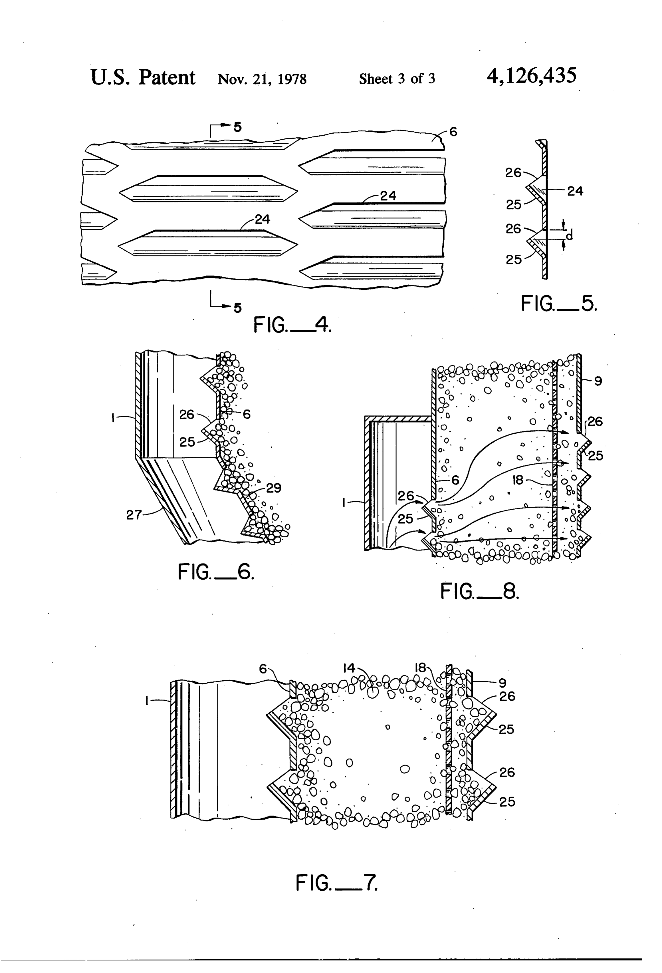
The present invention provides a remarkably simple port means 11 is operated can be varied and thus its process flow and arrangement of apparatus which per operation controls the rate at which the solid contact mits continuous operation for long periods of time with material moves downward in annular space between highly efficient separation of entrained solids, even of wall members 6 and 9. Elevator 10 may be any conven sub-micron size, contained in the feed gas. 35 tional solids conveyor suitable for transporting solids The method and apparatus of the invention are de vertically. A conventional bucket elevator provides a scribed with reference to the drawings of which: simple and dependable vertical transport means. A sec FIG. 1 is an elevational view of the separating appa ond solid transport means 12 is provided to convey ratus with the interior shown in the cut-away portion of particulate solid materials from the top of elevator 10 to the drawing; 40 solids inlet opening 5 in the top of vessel 1. A solids FIG. 2 is a horizontal cross-section of the separating separator 13, capable of separating finely divided solids vessel shown in FIG. 1 taken along the line 2-2; from the particulate solid contact material, is inserted in FIG. 3 is an elevational view of the separating vessel the flow path traversed by one or the other of solid shown in FIG. 1 with interior detail being shown in the transport means 11 or 12. Suitable solids separators cut-away portion of the drawing; 45 include oscillating screen separators which may be ei FIG. 4 is a detail of the louvered cylindrical surface ther reciprocating or gyratory screens having screens of the wall which contains the mass of particulate mate with openings sized to permit passage of the very finely rial; divided material separated from the gas under treatment FIG. 5 is a cross-section of the louvered cylindrical from the particulate solid contact material which circu surface shown in FIG. 4 taken along the line 5-5; 50 lates through the system. In the event that the finely FIG. 6 is a detail of the lower interior of the vessel; divided solids removed from the feed gas are oily or FIG. 7 is a detail of the particulate solid contact mate tacky in character, they may be removed from the solid rial as held by the two louvered cylindrical walls; contact material by burning them off or dissolving them FIG. 8 is a detail of the mass of contact material as instead of mechanically separating them by screening. held by the two cylindrical walls at the top of the vessel. 55 Third cylindrical wall member 18 is a perforated cylin Referring now to FIG. 1 of the drawings, cylindrical drical wall having a diameter 2 to 6 inches greater than vessel 1, usually having a flat or frusto-conical top and that of cylindrical wall member 9. The perforations are a tapered frusto-conical bottom, has gas inlet 2 disposed sized to permit passage of essentially all of the solid in its top, a solids outlet 4 in the bottom, and at least one contact material particles through them. The third cy solids inlet 5 laterally disposed in the top of the vessel. lindrical wall member is not essential if the solid contact A first cylindrical wall member 6 having a louvered material particles are large, e.g., -174 inch but is used surface and a diameter smaller than that of vessel 1 is to control lateral flow offinely divided contact material concentrically disposed in vessel 1 to leave an annular particles, e.g., 6-8 mesh through the louvre openings of space 7 between the sidewall of vessel 1 and wall mem cylindrical wall member 9. The function of cylindrical ber 6. Cylindrical wall member 6 is sealed at its upper 65 member 18 is more particularly described with refer end 8 to the top of vessel 1 to close off annular space 7 ence to FIG. 7.
at its top. Solid member 8 is attached to the top of wall FIG. 2 is a cross-section of vessel 1 taken at 2-2. member 6 and to the frusto-conical top of the vessel and Ribs 20 are strength members which hold first cylindri
Page 6
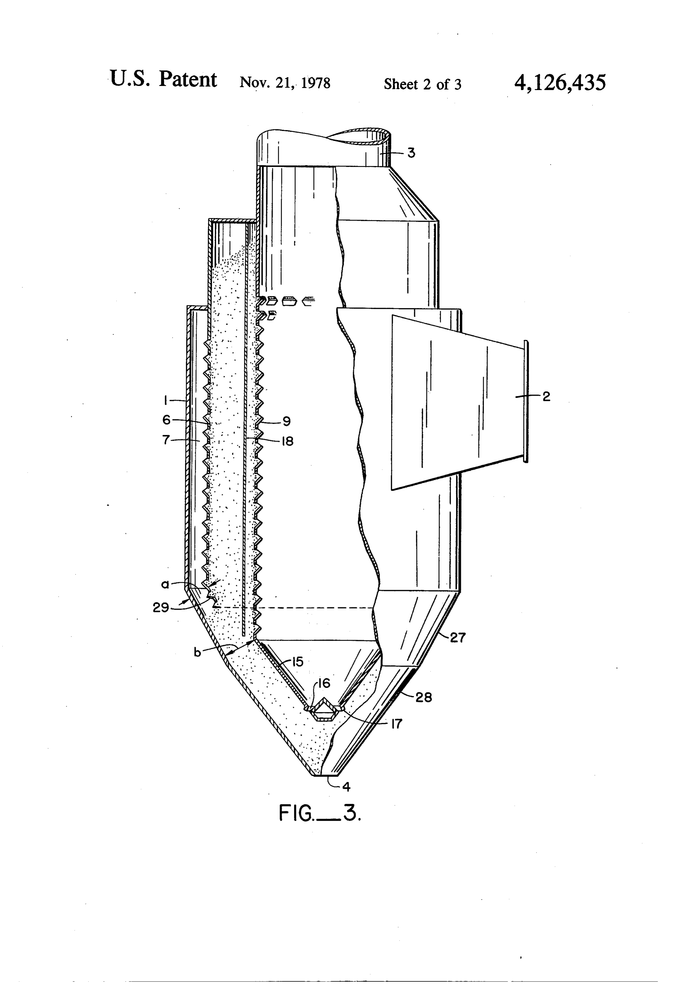
cal wall member 6 in place. The ribs 20 are slotted along making up the mass of solid contact material which, for their entire length to permit free flow of the feed gas most applications, range in size from about 2 mm. to 12 through annular space 7. Gas splitter 19 is a V-shaped mm, in diameter. Since the louver vanes are formed by member inserted in gas inlet 2 to direct the incoming gas perforating the cylindrical wall, the upper end of the into annular space 7 in both directions from inlet 2. In 5 vanes lies below the top of the louver opening by a addition to directing the feed gas in both directions distanced which varies with the vane angles. from inlet 2, splitter 19 prevents direct perpendicular Many of the gases containing entrained solids which contact of the feed gas with louvered wall member 6 may be treated pursuant to the invention to remove the which could result in plugging or partial plugging of the solids have high water vapor content ranging up to louvers in the area of direct perpendicular contact. O about 30 weight percent. When gases of this character FIG. 3 of the appended drawings is an elevational are being processed, it is necessary to maintain the tem view of vessel 1 partially cut away to show the interior perature of the interior of vessel 1 and of the particulate arrangement in greater detail, in particular, the details contact material 14 at a temperature above the dew of the conical closure 15 at the lower end of cylindrical point of the feed gas. In order to maintain above-dew wall member 9, slot 16 and exterior guard ring 17. 15 point temperatures in the separating system, it is desir FIG. 3 shows a particularly desirable and effective able to insulate at least lower frusto-conical section construction of the conical bottom of vessel 1. The shown in FIG. 3, the first solid transport means 11 and bottom is formed of two trusto-conical members 27 and the lower portion of elevator 10. 28. The upper frusto-conical section 27 has relatively FIG. 6 of the drawings is the detail of the lower steep sidewalls, its elements being at angle from 65 to 20 portion of cylindrical wall 6. When a filter unit is built 90 relative to the horizontal, while frusto-conical sec with cylindrical wall 6 as a vertical wall which termi tion 28 has sidewalls which are less steep, its elements nates vertically at the lower portion of the vessel so that being at an angle of 45 to 70 relative to the horizontal. the end of the vertical wall lies between the solid This arrangement of the two frusto-conical sections contact material which fills the annular space between permits smooth, uninterrupted flow of the particulate 25 cylindrical walls 6 and 9 and the solid contact material solid contact material 14 from the annular space be which accumulates in annular space 7 between vessel tween cylindrical sidewall members 6 and 9 to solids wall 1 and cylindrical wall 6 as a result of passage of the outlet opening 4. This flow is achieved in this manner solid contact material through the louvers of cylindrical with a reduction in the overall height of vessel 1 from wall 6, flow of the contact material out of annular space what its height would be if a single steep wall frusto 30 7 into the lower portion of the vessel and finally out of conical structure were employed to get dependable solids outlet opening 4 is very slow. Solid contact mate flow of the solid particulate contact material. rial tends to accumulate in annular space 7 and build up To insure that particulate solid material passing in that space blocking the louver openings in the lower through the louvers of cylindrical wall 6 and dropping part of louvered wall 6. The effect of this is to reduce to the bottom of annular space 7 flows down and out of 35 the area of louvered wall 6 through which the feed gas outlet opening 4 instead of accumulating in annular can flow into contact with the solids contact material space 7 the distance b between the lower end of wall 9 lying between walls 6 and 9. It has been found that this and conical surface 27 should not exeeed about ten problem can be overcome by bending the lower portion times the distance a between the lower end of wall 6 and (2 to 6 inches) of louvered wall 6 inwardly at an angle conical surface 27. Put another way, wall 9 should ex of 20' to 70'. The bent portion of the wall is shown as tend downward in the vessel to a point sufficiently 29 in the drawing. Instead of bending the lower 2-6 below the lower end of wall 6 that a line joining the inches of the louvered wall 6 inwardly, a solid metal lower end of wall 6 to the lower end of wall 9 has a plate (not shown) may be attached to the bottom of wall steeper angle to the horizontal than the angle of repose 6 to slope inwardly at 20 to 70 to the vertical. Either of the particulate solid contact material. The line re 45 bending wall 6 as indicated or attaching the inwardly ferred to would, of course, be the shortest line that inclined solid plate provides the desired improved flow. would connect a given point on the lower end of wall 6 The effect of placing this bent portion of louvered wall with a point on the lower end of wall 9. 6 (designated as 29) between the solid contact material To further facilitate the flow of contact material from lying between cylindrical walls 6 and 9 and the solid annular space 7 to solids outlet 4, the lower portion of 50 contact material which has accumulated in annular cylindrical wall 6 is bent inwardly at the bottom 29. The space 7 is to cause free flow of the material accumulated purpose and effect of this bend is more particularly in annular space 7 into the lower portion of the vessel described with reference to FIG. 6. and out solids outlet 4. The accumulation of solid FIGS. 4 and 5 of the drawings show the detail of the contact material in annular space 7 and the resultant louvered surface of first cylindrical wall member 6 and 55 blockage of the louver openings in the lower portion of a section of the louvered wall. The surface of the cylin cylindrical wall member 6 is prevented. drical wall member is perforated by staggered rows of FIG. 7 shows the detail of a cross-section of the annu louvers 24, as shown. Louver vanes 25 slant outwardly lar mass of solid contact material and the supporting from the surface wall member 6 and are inclined to the walls taken along the central section of the vessel. The vertical at an angle from about 15 to 80, preferably 30 size of the solid particulate contact material with which to 50. Louver openings 26 are sufficiently large so that the space between cylindrical walls 6 and 9 is filled may essentially all of the particles constituting a mass solid be varied depending on the character of the feed mate contact material 14 are capable of passing through rial. Where the finely divided solid particles contained them. The walls of a second cylindrical wall member in the feed are very small, it is preferred to use relatively are similarly louvered but the louver vanes extend in 65 smaller solid particulate material such as 6 to 8 U.S. wardly from the cylindrical wall member. Louver sieve size. Difficulties have been experienced during the openings of 0.1 to 0.5 inches are preferred since they use of the smaller sized solid contact material resulting assist in maintaining the desired small flow of particles from a semi-fluidizing of the contact material particles
Page 7
in the vicinity of cylindrical wall 9 and the resultant parts of wall members 6 and 9 is such that a solid un rapid flow of the contact material particles through the louvered surface constitutes the upper part of wall 6 and louvers of wall 9. This rapid flow of contact material this unlouvered surface faces an upper louvered surface through the louvers results in the accumulation of of wall 9. This arrangement of the relative vertical contact material particles at the bottom of the interior of 5 positions of the topmost louvers in walls 6 and 9 pre cylindrical wall member 9, the particles build up in this vented the rapid flow of solid contact material through interior and block off the louver openings in the lower the upper louvers of wall 9 and the accumulation of this portion of cylindrical wall member 9 thus reducing the overflow material in the interior of cylindrical wall 9 effective use of a substantial part of the contact material and eliminated the need for occasional shut downs with lying in the lower portion of the annular space between O loss in operating factor to remove the accumulated solid wall members 6 and 9. This accumulation requires peri contact material from the interior of cylindrical wall 9. odic interruption of operation to remove the accumu OPERATION lated contact material with a resultant loss in operating factor. This problem of carry over solid contact mate Gases containing finely divided solids which can be rial of small size through the louver openings of wall 15 treated for solids removal pursuant to the invention member 9 was overcome by placing a third cylindrical come from a variety of sources. Stack gases from boilers wall member having a diameter 1 to 10 inches greater fired with waste fuel and gaseous streams containing than that of cylindrical wall member 9 in the vessel entrained solids formed in cement plants or lime kilns between wall members 6 and 9. The surface of this third are illustrative feeds. Separation is effective whether the cylindrical wall member is perforated with perforations 20 suspended finely divided solids are of high or low den of a size sufficient to permit passage of essentially all of sity and efficient separation of solids having diameters the particles of solid contact material through them, the of about 0.5 microns is obtained. perforations covering the surface of third cylindrical The material constituting the mass of particulate solid wall member 18 cover the greater part of its surface but contact materials through which the feed gas passes the perforations are preferably terminated at the upper 25 should be temperature resistant at the temperature of end of wall member 18 at a point such that the highest the feed gas, preferably has rounded rather than angular of the perforations lay several inches below the highest surfaces to facilitate flow and prevent bridging and the of the louver vanes in wall member 9. The employment particles should have reasonable uniformity in size. of wall member 18 as described eliminated the fluidiza Particle sizes preferably range from about 2 mm. diame tion of the solid contact material particles and reduced 30 ter to 12.5 mm. diameter. A mass of particles in which their rate of flow through the louvers of wall member 9 the largest particles present in substantial quantity have with a resultant increase in the operating factor of the diameters not more than 3 to 4 times the diameter of the filter, smallest particles present in substantial quantity is con FIG. 8 of the drawings is the detail of the upper sidered a reasonably uniform mass and exhibits good portion of the vessel showing the arrangement of the 35 flow properties in the system. Coarse beach sand or louver openings in wall 6 relative to the position of the finely divided gravel are cheap, readily available and louver openings in cylindrical wall 9. When the vessel is constitute excellent contact masses. A San Simeon sand so constructed that wall members 6 and 9 are so lou containing 8 percent U.S. sieve size #6, 62 percent U.S. vered, that the uppermost louvers in wall 6 lie opposite sieve size #7, and 30 percent U.S. sieve size #8 is a the uppermost louvers in wall 9, a rapid flow of solid satisfactory coarse beach sand. Fine gravel consisting of contact material through the upper louvers in wall 9 66 percent U.S. sieve size #4 particles, 26 percent U.S. was observed. This rapid flow resulted in accumulation sieve size #5 particles, and the remainder only slightly of solid contact material in the interior of cylindrical larger than #4 and slightly smaller than #6 is a suitable wall 9, a build up of this material at a rate which may fine gravel for use in the process. In the event that gas slow up its exit through opening 16 with consequent 45 at very high temperature is to be treated then metal blockage of the louver openings in the lower portion of shot, ceramic or quartz beads and similar materials wall 9. The observed rapid flow of the solid contact which are more resistant to temperature fracture than material through the upper louvers of wall 9 appears to sand or gravel should be used as the solid contact mate be due to the fact that the feed gas entering the mass of rial.
contact material 14 through the upper louvers of wall 650 Flow rates of the feed gas through the particulate travels not only horizontally to escape through the solid mass ordinarily range from about 50 to 200 feet per louvered openings of wall 9, but also to travel upwardly minute. This velocity range is not critical and velocity in the contact material residing above the louvered can be varied over a considerable range as target levels portions of the two walls. This upper travel continues of plant through-puts and efficiency of separation vary. until the pressure resistance of the contact material 55 Pressure drop through the mass of solid particulate causes it to turn downward and ultimately exit through material is ordinarily in the range 2 to about 12 inches of the upper louvers of wall member 9. The result of this is water. Higher pressure drops are usually attended by that the gas flow rate through the upper louvers of wall higher efficiency of separation, but this is obtained at 9 is much greater than the rate through the louvers in the cost of an increased energy requirement to drive the the intermediate portion of wall 9. This higher rate of 60 feed gas through the separation unit. gas flow simply carries an excessive amount of solid In addition to varying the rate at which the feed gas contact material through the upper louvers of wall 9. is passed through the mass of particulate solid material This difficulty was overcome by blocking off the lou in a unit of the kind above-described, the rate at which vers in the upper portion of wall 6 so that the topmost the particulate solid is moved downward through the louver remaining in wall 6 lay below the topmost louver 65 annular space between the two louvered cylindrical in wall 9 by a distance in the range about 6 to 18 inches walls can be varied. The particulate solid can be moved and preferably about 12 inches. This arrangement of the at rates in the range about 0.5 to 40 feet per hour and relative position vertically of the louvers in the upper can in addition be moved only intermittently. Higher
Page 8
flow rates are employed with feed gases heavily loaded 1. In an apparatus for separating finely divided solids with finely divided solid material. Lower flow rates or from gas comprising:
intermittent flow where the particulate may be moving (a) a generally cylindrical vessel having a gas inlet during as little as one-sixth of the operating period may opening in its side wall, a gas outlet opening cen be employed where the feed gas is lightly loaded with 5 trally disposed in its top, a solids outlet centrally finely divided solids or when a very high percentage disposed in its bottom and at least one solids inlet removal of the finely divided solid is desired. opening disposed in its top laterally from the gas The method and apparatus can be operated over a outlet opening, wide range of pressure. Finely divided solids contained (b) a first generally cylindrical wall member having a in stack gases at near atmospheric pressure or in gases 10 diameter less than that of the vessel and disposed in effluent from coal gasification units or refuse combus the vessel to provide an elongated annular space tion disposal units which may be at 100 psi or above, can between said first wall member and the wall of the be effectively removed. vessel and in sealing engagement with the top por A prototype separation unit having a design capacity tion of the vessel, and the annular space between of 40,000 actual cubic feet per minute was installed at a 15 the first wall member and the wall of the vessel lumber mill in Washington to process stack gases from being unobstructed and in open communication a powerhouse boiler fired with hog fuel. The unit corre with the solids outlet at the bottom of the vessel, sponded in general design to that illustrated in FIG. 1 of (c) a second generally cylindrical wall member hav the drawings, except that the gas inlet was positioned 20 ing a diameter less than said first wall member about mid-way between the top and bottom of the ves disposed in said first wall member to provide an sel and the bottom of the vessel had the double tapered elongated annular space between the two wall conical bottom section illustrated in FIG. 3 of the draw members, the space enclosed by said second wall ings. The particulate solid material employed was - member being in open communication with the gas size. This unit as installed did not have the modifications outlet opening in the top of the vessel and with the 25 solids outlet at the bottom of the vessel, shown in FIGS. 6, 7 and 8. The annular mass of particu late solid materials had a thickness of 18 inches and a (d) a mass of particulate solid contact material filling height of 16 feet. The rate of flow of the mass of particu the annular space between the two cylindrical wall late solid material downwardly through the annulus members from the upper end of the second cylin between cylindrical wall members 6 and 9 shown in 30 drical wall member to the lower portion of the FIG. 1 was 1 foot per hour. At this rate, there was a vessel, said mass being in open communication slow, steady flow of a minor proportion of the particu with the solids outlet opening, and lar solid material through the louvers of cylindrical wall (e) the surfaces of both cylindrical wall members member 6 into annular space 7 and thence to the bottom being louvered surfaces formed by perforating said of the vessel and a similar slow flow of particulate solid 35 walls to form louver vanes inclined to the vertical through the louvers of the second cylindrical wall mem at an angle of about 15 to 80" and having louver ber 9 into the space enclosed by that wall member and openings sufficiently large that essentially all of the down to the conical closure at the bottom of cylindrical particles constituting the contact mass are capable wall member 9. The flow of particulate solids through of passing through the openings, the louver vanes the louvers kept the louvered surfaces clean and free of the first cylindrical wall member extending out from deposits of the finely divided solids entrained in wardly and those of the second cylindrical wall the gas feed. No louvered blockages or serious pressure member extending inwardly, drop increases due to accumulation of solids contained (f) the improvement wherein a short portion of the in the feed were experienced. lower end of the first wall member is bent inwardly During operation of this and other units and opera 45 so that the bent portion is inclined to the vertical at tions of a pilot scale unit, the problems to which the an angle of about 20 to 70. modifications of the apparatus described with reference fromIngasancomprising:
2. apparatus for separating finely divided solids to FIGS. 6, 7 and 8 were observed. By altering the rate (a) a generally cylindrical vessel having a gas inlet of flow of the solid particulate matter downwardly opening in its side wall, a gas outlet opening cen through the annular space lying between louvered cy 50 trally disposed in it top, a solids outlet centrally lindrical walls 6 and 9 as shown in FIG. 1 or by decreas disposed in its bottom and at least one solids inlet ing the gas feed rate or by both, it was possible to cope opening disposed in its top laterally from the gas with the problems to a degree that made it possible to outlet opening, - avoid frequent shutdowns. Meeting these problems in (b) a first generally cylindrical wall member having a this manner was obviously inefficient. Reducing the gas 55 diameter less than that of the vessel and disposed in flow rate reduced the useful capacity of the units and the vessel to provide an elongated annular space more rapidly circulation of the solid particulate matter between said first wall member and the wall of the increased operating costs since unnecessarily large vessel and in sealing engagement with the top por quantities of solid particulate material were being tion of the vessel, and the annular space between moved. 60 the first wall member and the wall of the vessel The modifications of the filter apparatus described in being unobstructed and in open communication FIGS. 6 and 8 have been tested in commercial scale with the solids outlet at the bottom of the vessel, apparatus and the modification of FIG. 7 in pilot scale (c) a second generally cylindrical wall member hav apparatus and have overcome the problems above ing a diameter less than said first wall member described and have resulted in a smooth, steady state 65 disposed in said first wall member to provide an operation in which highly effective removal of finely elongated annular space between the two wall divided solid particles from gases was achieved. members, the space enclosed by said second wall What is claimed is: member being in open communication with the gas
Page 9
outlet opening in the top of the vessel and with the unlouvered surface of the upper part of one of said solids outlet at the bottom of the vessel, walls faces an upper louvered surface of the other (d) a mass of particulate solid contact material filling wall.
the annular space between the two cylindrical wall 4. In an apparatus for separating finely divided solids members from the upper end of the second cylin 5 from gas comprising:
drical wall member to the lower portion of the (a) a generally cylindrical vessel having a gas inlet vessel, said mass being in open communication opening in its side wall, a gas outlet opening cen with the solids outlet opening, and trally disposed in its top, a solids outlet centrally (e) the surfaces of both cylindrical wall members disposed in its bottom and at least one solids inlet being louvered surfaces formed by perforating said 10 opening disposed in its top laterally from the gas walls to form louver vanes inclined to the vertical outlet opening, at an angle of about 15 to 80 and having louver (b) a first generally cylindrical wall member having a openings sufficiently large that essentially all of the diameter less than that of the vessel and disposed in particles constituting the contact mass are capable the vessel to provide an elongated annular space of passing through the openings, the louver vanes 15 between said first wall member and the wall of the of the first cylindrical wall member extending out vessel and in sealing engagement with the top por wardly and those of the second cylindrical wall tion of the vessel, and the annular space between member extending inwardly, the first wall member and the wall of the vessel (f) the improvement wherein a perforated third cylin being unobstructed and in open communication drical wall member having a diameter of 1 to 10 20 with the solids outlet at the bottom of the vessel, inches greater than the diameter of the second wall (c) a second generally cylindrical wall member hav member is disposed between the first and second ing a diameter less than said first wall member wall members, the perforations of said third wall disposed in said first wall member to provide an member being sufficiently large to permit essen elongated annular space between the two wall tially all of the solid contact material particles to 25 members, the space enclosed by said second wall pass through them. member being in open communication with the gas 3. An apparatus for separating finely divided solids outlet opening in the top of the vessel and with the from gas comprising: solids outlet at the bottom of the vessel, (a) a generally cylindrical vessel having a gas inlet (d) a mass of particulate solid contact material filling opening and a gas outlet opening in its surface, and 30 the annular space between the two cylindrical wall (b) a filter element for use in separating finely divided members from the upper end of the second cylin solids from gas positioned in said vessel between drical wall member to the lower portion of the said gas inlet opening and said gas outlet opening vessel, said mass being in open communication and comprising an elongated mass of particulate with the solids outlet opening, and solid contact material disposed between two con 35 (e) the surfaces of both cylindrical wall members centric cylindrical walls, one being an inner wall being louvered surfaces formed by perforating said and the other an outer wall with respect to each walls to form louver vanes inclined to the vertical other, the outer cylindrical wall having a louvered at an angle of about 15 to 80' and having louver surface formed by perforating said wall to form openings sufficiently large that essentially all of the outwardly extending louver vanes and the inner 40 particles constituting the contact mass are capable cylindrical wall having a louvered surface formed of passing through the openings, the louver vanes by perforating said wall to form inwardly extend of the first cylindrical wall member extending out ing louver vanes, the louver vanes of both walls wardly and those of the second cylindrical wall being at angles of about 15' to 85’ to the vertical member extending inwardly, and the louver openings in both walls being suffi 45 (f) the improvement wherein the upper portion of the ciently large that essentially all of the solid contact first cylindrical wall member is unlouvered, not material particles are capable of passing through perforated, and the second cylindrical wall mem them and the upper surfaces of the two cylindrical ber has an upper surface which has a louvered walls being so louvered that the louvered portion portion which faces the unlouvered portion of the of one of said walls extends above the louvered 50 first wall member.
portion of the other of said walls so that a solid sk k t
Provenance
- Collection
- Cited prior art
- Original PDF
- patentimages.storage.googleapis.com →
- Filed
- 1976-09-13
- Pages
- 9
- Method
- pdftotext (the PDF's own text layer) + pdftoppm 300dpi page scans
- Source
- Google Patents bibliographic record
- Granted
- 1978-11-21
- Inventors
- Richard G. Reese; Combustion Power Co Inc
- Transcribed from
- patentimages.storage.googleapis.com →