patent · US2482551
Combination igniter and flame
20 September 1949
Page 1
Drawing sheet — no readable text.
Page 2
Drawing sheet — no readable text.
Page 3
Patented Sept. 20, 1949 2,482.551
COMBINATION GN TER AND FLAM
OETECTOR
Theodore Y., Korsgren, Winnetka, II., O to Stewart-Warner Corporation, Chicago, i.
a corporation of Wirginia
Application October 8, 1945, Serial No. 621,42
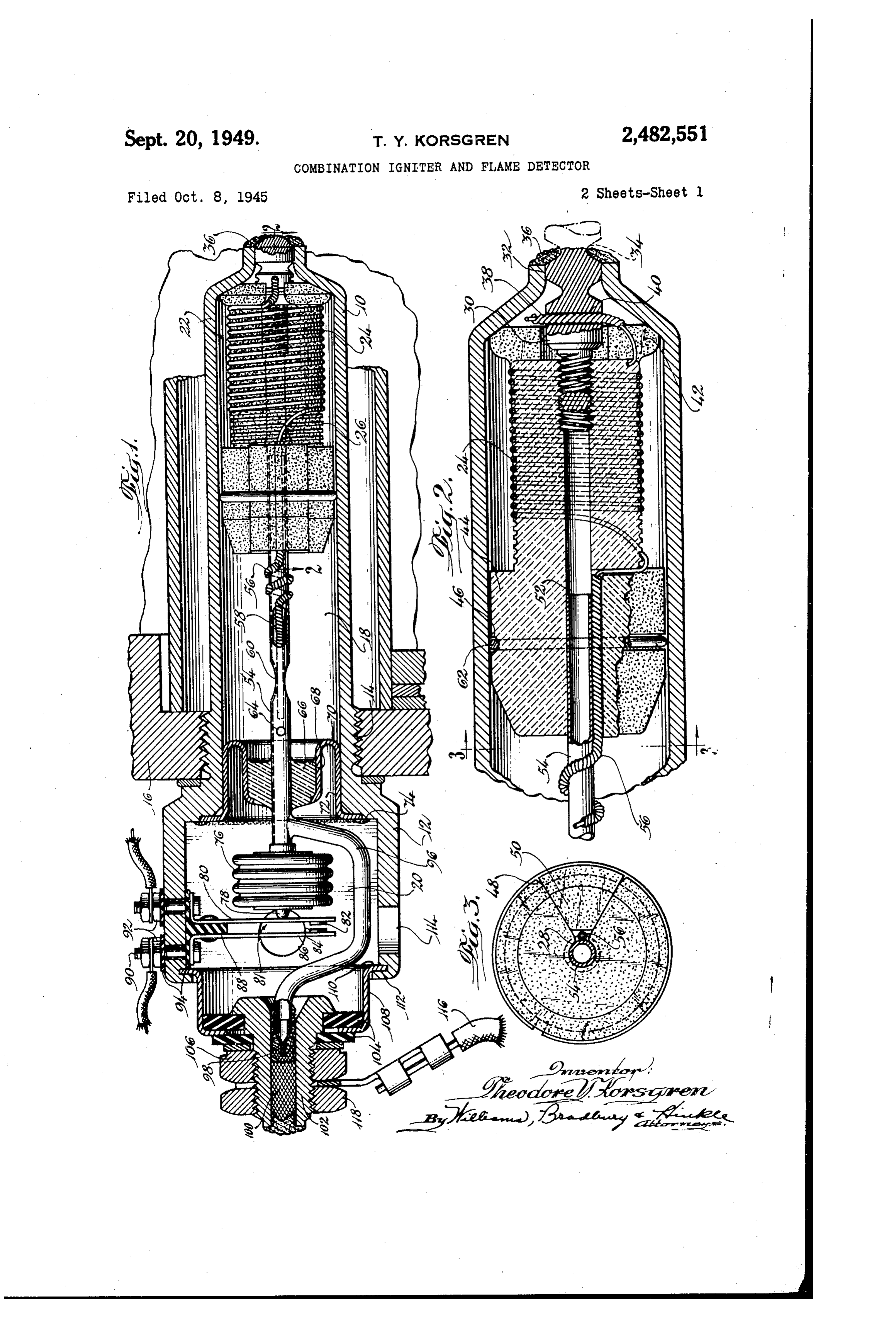
The present invention relates to heaters and the direction indicated by the arrows along the more particularly to a mechanically simple dual line 3-3 of Fig. 2;
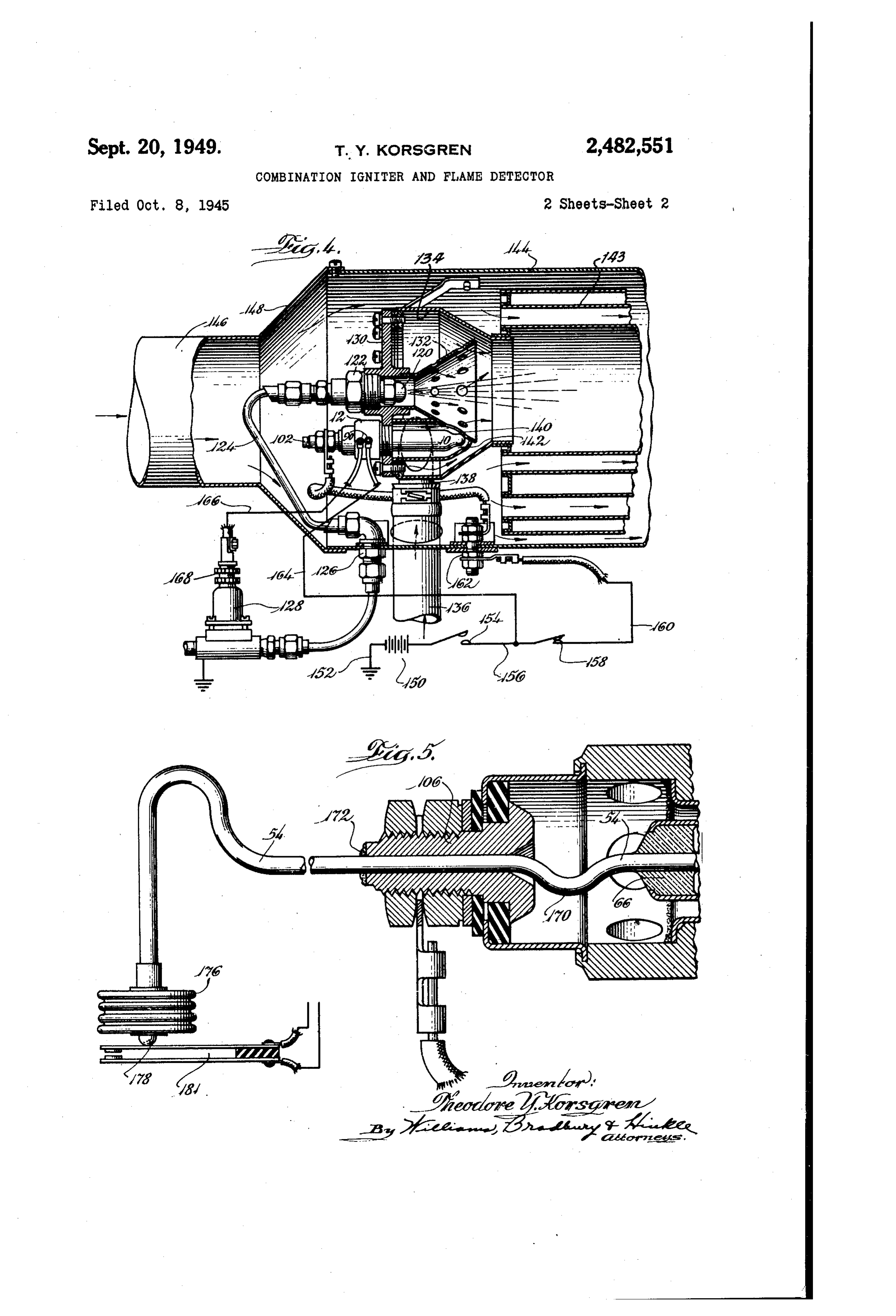
purpose device which serves as a flame detector Fig. 4 is a somewhat diagrammatic longitu and also as an igniter for instituting combustion. dinal Sectional view of a portion of a heater In heaters or furnaces of the liquid or gaseous illustrating the device shown in Figs. 1, 2, and 3 fuel burning type, some means is required for in use; and starting combustion. This means usually takes Fig. 5 is a fragmentary longitudinal sectional the form of a high tension electric spark Or a view of a device embodying an alternative form gas pilot flame or in some cases a hot wire low of the present invention. The portion of the de voltage resistance element. Frequently also, 0 vice broken away in Fig. 5 may be identical to particularly in gas burning heaters, the ignition the similar portion of the alternative device means takes the form of an electric spark which illustrated in Fig. 1.
is used only occasionally for starting a gas pilot, Referring to Fig. 1 of the drawings, the igniter the gas pilot serving as the principal igniter. comprises a generally cylindrical shell or thimble In addition to the ignition mechanism, heaters ls to having a comparatively thin wall and formed and furnaces usually have what is known as a integrally with a somewhat heavier hexagonal flame detector. The purpose of this device is head 2 at one end. Adjacent the hexagonal to operate controls such that the fuel cannot head the tubular portion is provided with threads be turned on or will be turned off if it is already 4 for easy attachment of the device in a heater, on, whenever the pilot is out or combustion in 20 Such as is indicated generally by the numera i 6. the main burner is not taking place. The body portion comprising the thimble O It is therefore an object of the present inven and head 2 is formed of heat and corrosion tion to provide a novel device which serves both resistant stainless steel or other alloy, which is as an igniter and as a flame detector. adapted to be operated in a somewhat corrosive A further object of the present invention is 25 atmosphere at red heat, to provide a novel device which interrupts the For convenience, the cylindrical cavity within fuel supply to a furnace or heater with which it the thimble fo is indicated by the numeral 8 is used if combustion ceases, or if the device is and this cavity is connected to a chamber 20 of not in condition to function properly as an Somewhat larger diameter located within the igniter. 30 head portion 2.
A further object of the present invention is The thimble O is provided internally with a to provide a novel device for accomplishing the heating element 22 located within the cavity 8 above set out objectives at lower cost and with which when energized heats the shell O by greater reliability than known devices with radiation and by conduction through an inert which I am acquainted. 35 gas which fills the thimble 0. This heating ele Still another object of the present invention ment comprises a wire 24 of tungsten, tungsten is to provide a novel combined igniter and flame alloy, or the like, wound in a helical groove detector in which the igniter element operates formed in a ceramic core 26. The core is pref directly on commonly used line voltages. erably made of thorium oxide, aluminum silicate Other objects and advantages will become ap 40 or other electrical insulating material which is parent from the following description of a pre adapted for operation at high temperatures. ferred embodiment of my device which is illus The core 26 has an axial opening 28 threaded at trated in the accompanying drawings. One end to receive a terminal stud 30. This In the drawings, in which similar characters of terminal stud extends outwardly through an reference refer to similar parts throughout the 45 Opening 32 of comparable size formed at the several views: lower end of the shell O by necking the shell Fig. 1 is an enlarged longitudinal Sectional down to comparatively Small diameter. For view of one form of a device embodying features convenience in assembly, the stud is formed with of the present invention; a groove 34. Such that after the study has been Fig. 2 is a longitudinal sectional view of a 50 inserted through the opening 32 and has been portion of the device illustrated in Fig. , drawn Secured to the shell by brazing, as at 36, the to larger scale, This view is taken along the line portion of the stud which extends beyond the 2-2 of Fig. 1 in the direction indicated by the end of the igniter can be broken off. arrows: The end of the wire 24 adjacent the terminal Fig. 3 is a transverse sectional view taken in 55 stud 30 is enclosed within a pad coil 38 which
Page 4
extends through a transverse hole 4 drilled in blade 80 carries a contact button 2 which co the stud. 30. This pad coil serves to provide good Operates with a similar button 4 located at the electrical conductivity between the wire 24 and end of a second contact strip B. These strips the stud 30, and serves to lower the electrical are insulated from each other by a block of suit current load carried by the wire at the point able insulating material B, are connected by a where it passes through the stud, thereby pre plastic rivet, and are attached to the side wall venting overheating of the wire at the enclosed of the head 2 by means of terminal screws 90 portion. The pad coil also provides a connec and nuts 92 which are insulated from the head tion less easily broken than if the wire 24 were 0 is2apparent secured directly to the stud.
by suitable insulating washers or strips 94. It from the above that when the bellows
The portion of the core 2 around which the 6 is contracted, the contacts 82 and 84 will be coal 24 is wound is suficiently smaller in diam Separated and therefure no circuit will be estab eter than the opening so that the wire 24 can lished between the two terminals 90. Upon the not become grounded by touching the wall of bellows 76 being extended a predetermined the thimble. To keep the core in alignment, it 5 amount, however, the contacts 2 and 84 are is provided at its lower end near the stud 30 brought together, thus completing a circuit be with a flange 42 which rests against the face of tween these terminals.
the inwardly tapering side wall of the thimble The tube 54 in a position slightly below the while a head 44 having a circumferentially ex bellows 76 is welded to a branch tube 96 which tending groove 4S. is formed at the opposite end 20 is bent outwardly, upwardly, inwardly and finally of the core and is of such size that it fits loosely into a position in axial alignment with the tube within the thimble. The head 44 is formed with 54, the bends just described being for the purpose a sector shaped slot 4 in one side thereof into of clearing the bellows and switch. which is fitted a complementarily shaped block 50 After the device has been assembled as de of similar material. This block when in place in 25 Scribed, the upper end of the tube S is connected the slot provides the head with a substantially to a vacuum pump to evacuate the chamber 8, continuous circumference. the tube 54, the bellows 7, and the branch tube The head 44 has an axial bore 52 into which 96. After evacuation the system is refilled to a tube 54 is loosely fitted so that a small amount approximately atmospheric pressure with a suit of relative longitudinal movement between the 30 able lamp gas, such as a mixture of approxi parts brought about by thermal expansion and mately 87 per cent argon and 13 per cent nitro contraction is not inhibited. The upper end of gen, for instance. The upper end of the tube 6 the wire 24 is provided with a pad coil 56, the is then pinched and sealed of with solder as at lower portion of which lies against the tube S4 98 and is soldered to a short length of metal braid and in the sector shaped slot 48 while the upper 00 which extends axially through and is soldered end and the enclosed wire 24 are wrapped around to a terminal Stud O2, this stud being secured the tube 54 about two turns and then extended by insulating washers 04 and a nut 06 to a into a slot 56 in one side of the tube 54. Thus sheet metal cap 08. The lower end of this cap the upper end of the pad coil is enclosed within is flanged outwardly as at and is secured to the tube, this portion of the tube subsequently 40 the upper end of the head 2 by swaging as at being pinched flat as at to hold the pad coll 2. The bellows 76 and electric switch indicated in place and serve as an electrical connection generally by the numeral 8 are ventilated by air between the tube and the coll. which can pass through a plurality of holes (4 After the heating element has been assembled, formed in the head f2.
as above described, the sector shaped block 50 When the igniter terminals of the above de is put in place in the longitudinal slot 48 and vice are suitably connected, that is, by a lead is secured by a split ring 2 located in the cir 6 secured to the terminal OB by a nut i? 8 and cumferential slot 46. As will be seen in Fig. 3, by the other side of the circuit being grounded, the inner end of the sector shaped block 50 does the coil 24 heats up much like the filament in not extend quite to the tube 24 but leaves suf 50 an ordinary incandescent light bulb and quickly cient space to accommodate the wire 24 and pad heats the lower portion of the shell to a tem coil 56. perature sufficiently high for the ignition of a Slightly outward of the pinched portion 60, mixture of air and a liquid or gaseous fuel. At the tube 54 is provided with a small hole 64 to this temperature the inert gas surrounding the provide a gas communication path between the 55 coil is heated to a high temperature and increases cavity 8 and the interior of the tube 54. Just the pressure within the chamber 8. This pres above the hole 64 the tube 4 is sealed within a Sure is communicated through the opening 64 to glass bead 66, the Outer portion of which is sealed the interior of the tube U4 and thence to the to a metal cup 68. The outer portion of the cup bellows 76. The bellows are therefore elongated has a reverse bend as at T and a longitudinal 60 and raise the switch blade D and complete a extending portion 2 which lies against the inner circuit between the terminals and 92 by way wall of the upper portion of the thimble O. The S. Switch blade 80, contacts 82 and 84 and blade extreme end of the portion 2 is flanged over and brazed to the body portion of the igniter as In Fig. 4: I have shown the igniter suitably ar at 74. 65 ranged in one type of heater. This heater com In order to preserve a gas-tight relationship prises a spray nozzle 20 mounted in a fitting between the tube. 54 and the metal cup 68, the 22 which in turn is connected by a tube 24 tube, the cup and the glass bead SS are selected through a bulkhead type fitting 2 to a magnetic from materials having similar coeficients of ex shut-off valve 28, the inlet side of the magnetic pansion. 70 valve being connected to a source (not shown) The upper end of the tube 4 is connected to of fuel under pressure.
a small Sylphon type bellows TS, the opposite The nozzle f20 is mounted in a plate 30 which end of which carries an insulating button 8 carries a conical type combustion chamber 2 adapted to raise the lower blade of an electric located within an air plenum chamber 34. Air switch 8 when the bellows is extended. The 5 is brought tangentially into this plenum cham
Page 5
ber by way of a tube 36 connected to a fitting the combustion air, the mixture being ignited by 38 welded to the side wall of the chamber 34. the hot tip of the thimble O.
Beneath the nozzle 20 the cone 32 has an The hot products of combustion thus formed opening 40 which communicates with a pocket pass through the heat exchanger and to the 42 in which the thimble O of the igniter is 5 exhaust not shown, with the result that ventilat located, the igniter being threaded into an open ing air passing inwardly through the duct 46 ing in the plate 30. and through the heat exchanger is quickly raised The outlet end of the plenum chamber 84 is in temperature until the thermostatic igniter connected to a heat exchanger 43 of any suit switch 58 opens, thereby de-energizing the able type, while a jacket 44 surrounds and en 0 igniter.
closes the heat exchanger and burner. Wentilat Even though the igniter is de-energized, the ing air is introduced through a duct 46 con temperature of the inert gas does not decrease nected to the jacket 44 by an adapter f48 so Sufficiently to open the switch. 8 because the that air passes around the burner and through heat of combustion keeps the igniter thimble fo the heat exchanger so as to absorb heat from 5 quite hot. On the other hand, if at any time combustion taking place at the burner 32. The combustion ceases, the thimble O, which is of opposite end of the heater, including a portion comparatively thin metal, cools quickly so that of the heat exchanger and the heater exhaust the temperature of the inert gas drops suff connection, are not shown since the present in ciently to permit the bellows 76 to contract vention is directed to the combination igniter and 20 enough to open the switch 8 very soon after com flame detector rather than to any specific type of bustion ceases. As soon as the switch opens, heater. the magnetic valve 28 is de-energized, thereby The electrical circuit shown in Fig. 4 comprises interrupting the flow of fuel to the nozzle 20. a source of electrical energy indicated for con In the above description of the operation of venience by the battery 50, although usually 60 25 the heater and control mechanism, it is assumed cycle alternating current at about 110 volts po that a source of air under pressure is connected tential is more generally used, one side of which to the duct 46 and to the tube 36 so as to pro is grounded as at 52, while the other side is duce a flow of both ventilating air and combus connected through a master control switch 54 tion air to the heater. Such a source of air under to a wire 56 which in turn is connected through 30 pressure may comprise one or more blowers or a thermostatic igniter switch 58 to a wire 60, may comprise connections to a scoop or ram on this wire leading to the terminal 02 by way of an airplane. N a bulkhead type electrical conductor 62. Under some conditions it may be desirable to One of the terminals 90 is connected by a lead locate the Switch 8 remotely from the igniter. 64 to the wire f36 at a point between the Such a scheme is illustrated in Fig. 5. In this switches f S4 and 58, while the other terminal 90 embodiment of the invention the tube 54 extends is connected by a wire 66 to the terminal 68 through the glass bead 66 as in the previous of the magnetic valve 28, the other side of this embodiment and is provided in the space between valve being grounded. The valve 28 is of the 40 the bead 66 and the terminal O6 with a U-bend type which is closed until energized and recloses 70 to introduce resiliency to take up slight end as soon as de-energized. The master switch fj4 wise expansion and contraction between the ter is preferably of the over center or snap action minal OS and the bead 66. Above the U-bend type which remains closed or open as set. The 70, the tube 54 extends through the terminal thermostatic igniter Switch 58 may be of the bi 06 and is soldered thereto as at 72. From the metal type sensitive to the temperature of the terminal the tube 54 continues for any reason ventilating air downstream of the heat exchanger able length and at its end is connected to a bel lows 76 similar to the bellows 76. These bel 43, so that this switch is normally closed when lows are provided with an insulating knob & cold and opens the circuit therethrough when which operates a leaf type switch 8 similar to the temperature of the ventilating air rises suffi the switch 8. It operates in the same manner ciently to indicate that combustion is well started. as switch 8 and may be connected in the cir The device illustrated in Fig. 4 operates in the cuit illustrated in Fig. 4 in place thereof. following manner: Whenever heat is desired, Although I have shown only one electrical cir switch 54 is closed. This energizes the igniter cuit for taking advantage of the features of the by way of wire 56, igniter switch 58, wire 60, 55 present invention and have shown switches of and bulkhead terminal 62 to the terminal 02 only the single pole single throw type, it will of the igniter, through braid 00 and branch tube be appreciated that this device is adapted for 96, to the tube 54 and thence to pad coil 56 and use in all types of flame detector circuits; and heating wire 24 to ground by way of pad coil 38, that when appropriate in such circuits, it is in terminal stud 30, and shell O. 60 tended that the device of the present invention In a matter of ten seconds or so, the igniter be provided with gang type Switches, if necessary, will have reached igniting temperature and will and that these switches can be either of the nor have heated the inert gas in the space 8 and ally open or normally closed types and that they raised the pressure thereof, which communicates may be arranged so that there is a temperature by way of opening 64 and tube 54 to the bellows 65 differential between operation of certain of the 76. This causes the bellows to elongate until the switches and operation of others of the switches. knob 78 brings contact 82 against contact 84. As This, of course, can be accomplished in a well soon as this happens, the magnetic valve 28 is known manner by so arranging the switches that energized by way of lead 64, terminals 90 and the knob 78 or 78 must move farther to operate 92 and switch 8, and lead 66 to the terminal some switches than to operate others. 68 of the magnetic valve and thence to ground. Having described my invention, what I claim The valve therefore opens and permits fuel under as new and useful and desire to secure by Letters pressure to pass therethrough and through the Patent of the United States is: tube 24 to the spray nozzle 120. The fuel issues 1. A combination igniter and flame detector from the nozzle in a fine mist which mixes with 75 comprising, an electric resistance type heating
Page 6
element adapted to be heated to incandescence, closing said heating element and slightly spaced a metal envelope enclosing said heating element therefrom so that said envelope may be heated and slightly spaced therefrom SO that said en to ignition temperatures by said heating element, velope may be heated to ignition temperatures means for connecting electric leads to said heat by said heating element, means for connecting ing element, an electric switch, a pressure re electric leads to said heating element, a movable Sponsive device adapted to operate said switch member, a pressure responsive device adapted to upon an increase in pressure, a tube connected move Said member upon a change in pressure, at One end of said pressure responsive device and passage forming means connecting said pressure extending into said envelope, a glass to metal responsive device to said envelope so that said 10 Seal between said tube and said envelope so that envelope Said pressure responsive device and the said envelope, said pressure responsive device, last Said means comprise a single gas tight sys and Said tube comprise a single gas tight sys ten, and a quantity of inert gas filling said ten, a quantity of inert gas filling said system System. to substantially atmospheric pressure, means 2. A combination igniter and flame detector 5 forning a chamber connected at one end to said comprising, an electric resistance type heating envelope, and said chamber enclosing said switch element adapted to be heated to incandescence, and said pressure responsive device. a metal envelope enclosing said heating element 5. A combination igniter and flame detector and slightly Spaced therefrom so that said en comprising, an electric resistance type heating velope may be heated to ignition temperatures 20 element adapted to be heated to incandescence, by Said heating element, means for connecting a metal envelope enclosing said heating element electric leads to said heating element, an electric and slightly spaced therefrom so that said en Switch, a pressure responsive device adapted to velope may be heated to ignition temperatures Operate Said Switch upon an increase in pressure, by said heating element, one electrical end of said passage forming means connecting said pressure 25 heating element being grounded to said envelope, responsive device to said envelope so that said a tube connected to the other electrical end of envelope said pressure responsive device and the said heating element, said tube extending out of last Sald means comprise a single gas tight sys said envelope, a glass to metal seal forming a tem, and a quantity of inert gas filling said sys gas tight connection between said tube and said tem to substantially atmospheric pressure. 30 envelope and insulating said tube electrically 3. In a combination igniter and flame detector, from said envelope, a pressure responsive device an electric resistance type heating element connected to said tube exteriorly of said envelope adapted to be heated to incandescence, a metal so that said envelope, tube and pressure respon envelope enclosing said heating element and sive element form a single gas tight system, and slightly spaced therefrom so that said envelope a quantity of inert gas filling said system sub may be heated to ignition temperatures by said stantially to atmospheric pressure. heating element, means for connecting electric THEODORE Y. KORSGREN. leads to said heating element, an electric switch, REFERENCES CTED a pressure responsive device adapted to operate said switch upon an increase in pressure, a tube 40 The following references are of record in the connected at One end to said pressure responsive fille of this patent:
device and extending into said envelope, a glass to metal seal between said tube and said envelope UNITED STATES PATENTS So that said envelope said pressure responsive de Number Name Date vice and said tube comprise a single gas tight 829,810 Swan ------------ Aug. 28, 1906 system, and a quantity of inert gas filling said 1,453,461 Hotman ----------- May 1, 1923 system to substantially atmospheric pressure. 2,031,985 Stoll ------------- Feb. 25, 1936 4. A combination igniter and flame detector 2,063,613 McCarthy ---------- Dec. 8, 1936 comprising, an electric resistance type heating 2,258,042 Brace -------------- Oct. 7, 1941 element adapted to be heated to incandescence, 50 2,297,917 Schmidt ------------ Oct. 6, 1942 a heat and Corrosion resistant metal envelope en
Provenance
- Collection
- Cited prior art
- Original PDF
- patentimages.storage.googleapis.com →
- Pages
- 6
- Method
- pdftotext (the PDF's own text layer) + pdftoppm 300dpi page scans
- Source
- Google Patents bibliographic record
- Granted
- 1949-09-20
- Transcribed from
- patentimages.storage.googleapis.com →