patent · US616035
Twentietiis to agnus m
13 December 1898
Page 1
Drawing sheet — no readable text.
Page 2
Drawing sheet — no readable text.
Page 3
Drawing sheet — no readable text.
Page 4
UNITED STATES PATENT OFFICE.
JULIUS L. THOMA, OF KANSAS CITY, MISSOURI, ASSIGNOR OF SEVENTEEN
TWENTIETILS TO AGNUS M. L. MILLER, CRESCENT P. BROD, ILOUISE. V.
PANTOFF, AND JOHN POTZNER, OF SAME PLACE.
ELECTRIC MOTOR.
SPECIFICATION forming part of Letters Patent No. 616,035, dated December 13, 1898. Application filed June 20, 1898, Serial No. 683,935, (No model.)
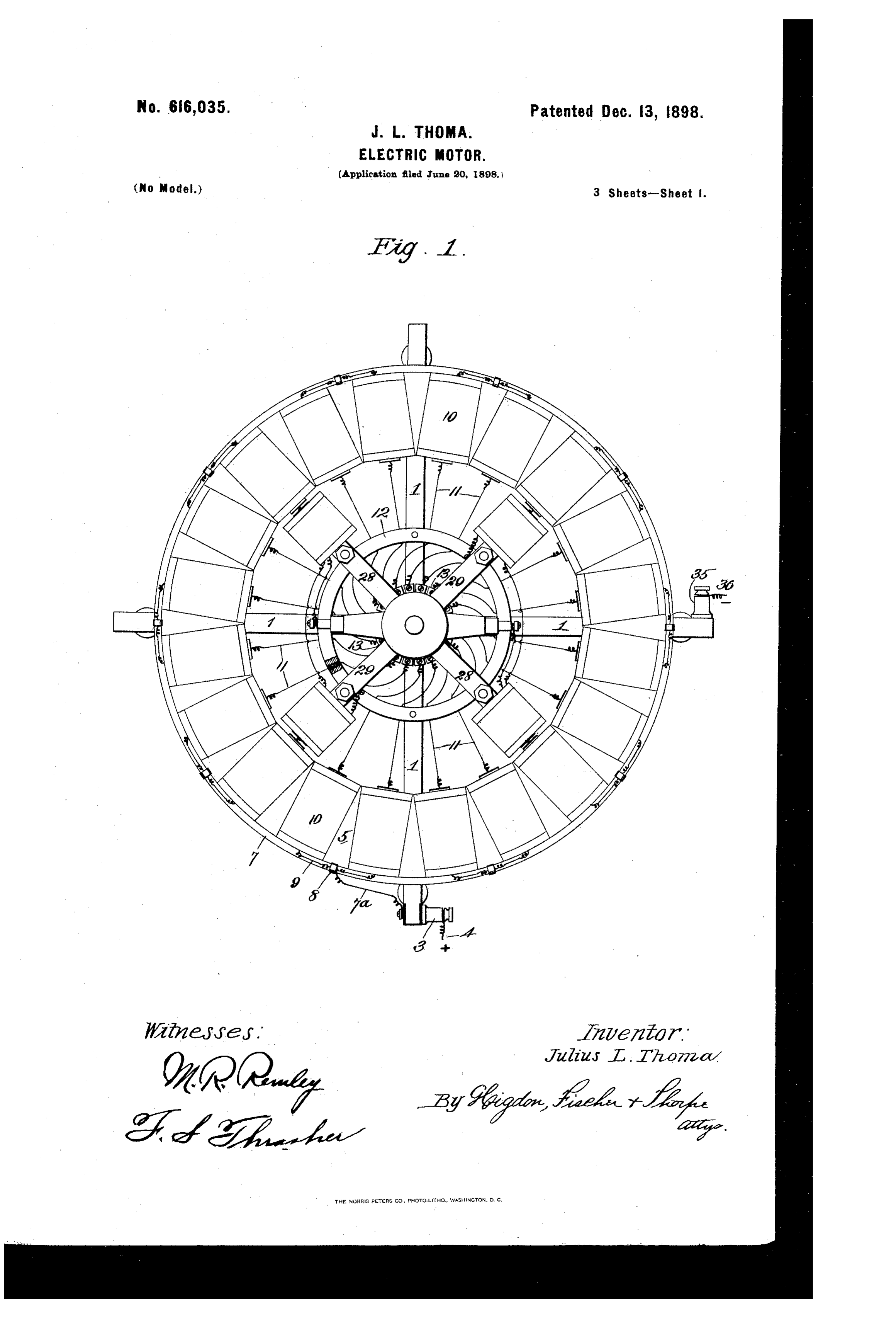
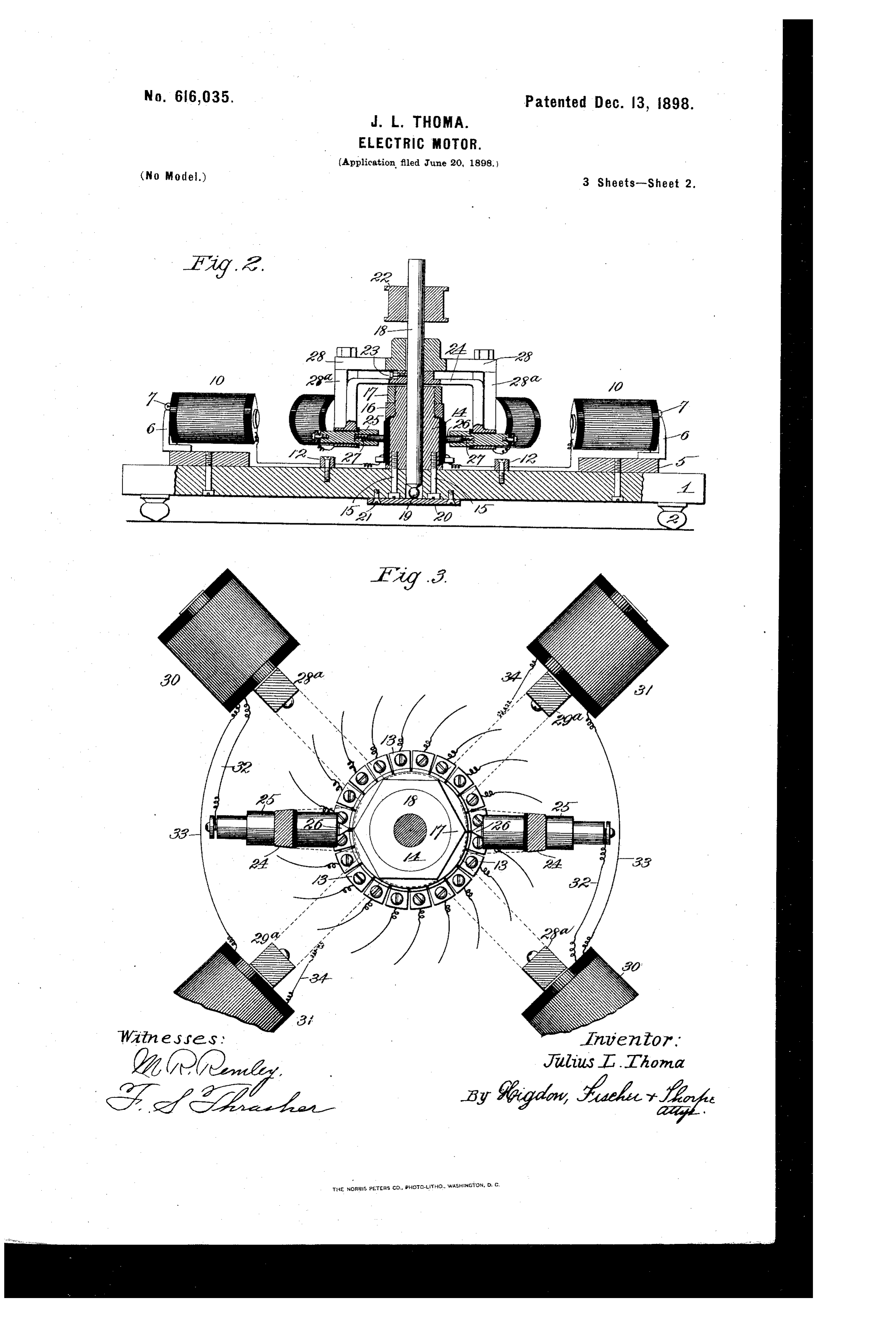
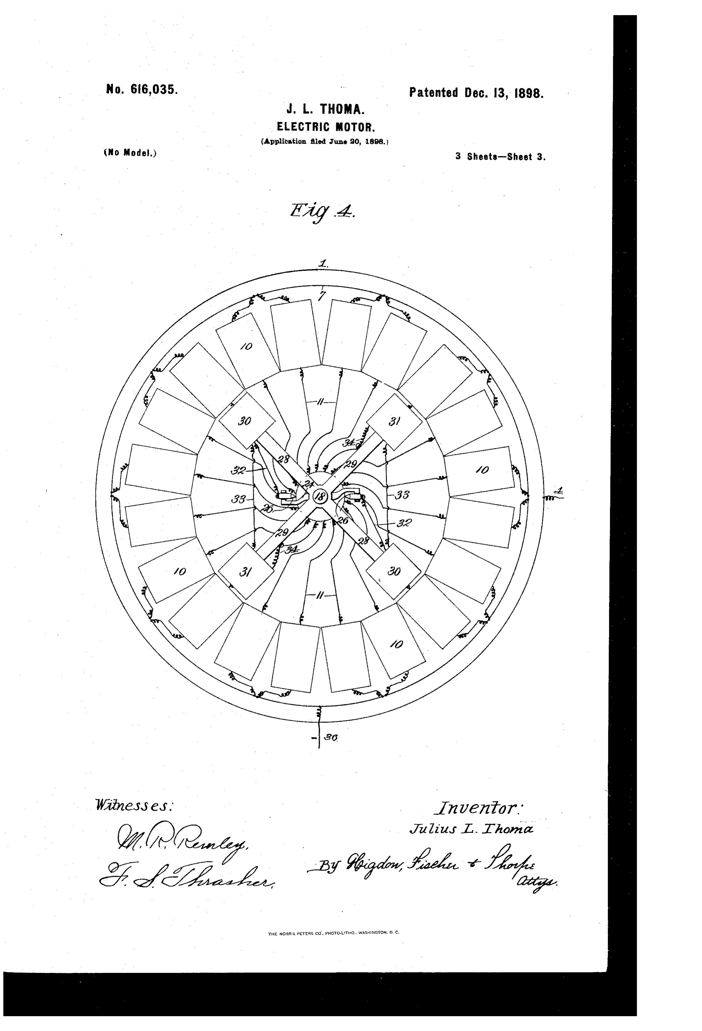
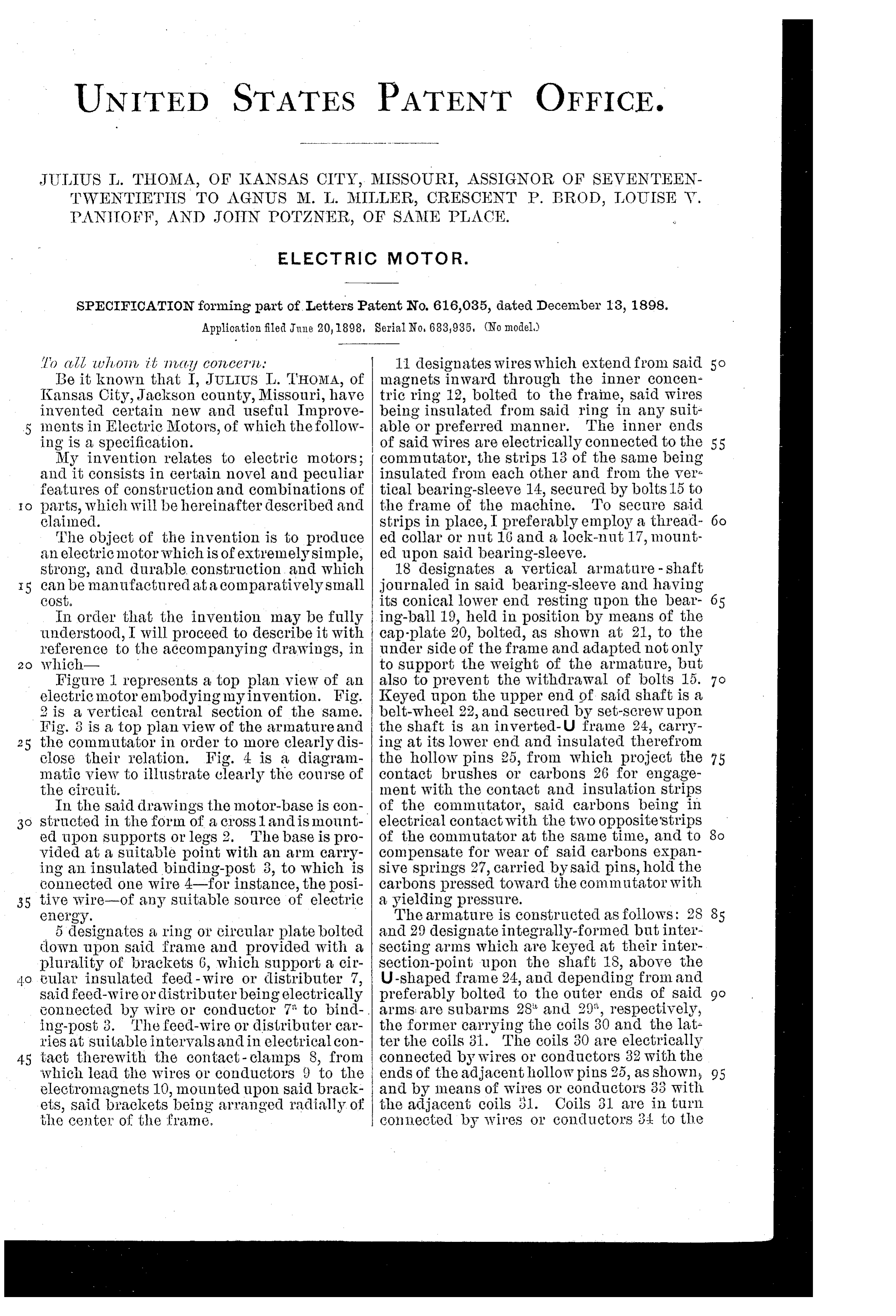
To ?till uhon, it in?tity conce71. 11 designates wires which extend from Said 5O Be it known that I, JULIUS L. THOMA, of magnets inward through the inner concen Ransas City, Jackson county, Missouri, have tric ring 12, bolted to the frame, said wires invented certain new and useful Improve being insulated from said ring in any suit 5 ments in Electric Motors, of which the follow able or preferred manner. The inner ends ing is a specification. of said wires are electrically connected to the 55 My invention relates to electric motors; commutator, the strips 13 of the same being and it consists in certain novel and peculiar insulated from each other and from the Vel features of construction and combinations of tical bearing-sleeve 14, secured by bolts 15 to 1o parts, which will be hereinafter described and the frame of the machine. To secure Said claimed. strips in place, I preferably employ a thread- 6o The object of the invention is to produce ed collar or nut 16 and a lock-nut 17, mount an electric motor which is of extremely simple, ed upon said bearing-sleeve. strong, and durable construction and which 18 designates a vertical armature - shaft 15 can be manufactured at a comparatively small journaled in said bearing-sleeve and having COSt. its conical lower end resting upon the bear- 65 In order that the invention may be fully ing-ball 19, held in position by means of the understood, I will proceed to describe it with cap-plate 20, bolted, as shown at 21, to the reference to the accompanying drawings, in under side of the frame and adapted not only 20 which to support the weight of the armature, but Figure I represents a top plan view of an also to prevent the withdrawal of bolts 15. 7 O electric motor embodying myinvention. Fig. Keyed upon the upper end of said shaft is a 2 is a vertical central section of the same. belt-wheel 22, and secured by Set-screw upon Fig. 3 is a top plan View of the arnature and the shaft is an inverted-U frame 24, carry 25 the commutator in order to more clearly dis ing at its lower end and insulated therefrom close their relation. Fig. 4 is a diagram the hollow pins 25, from which project the 75 matic view to illustrate clearly the course of contact brushes or carbons 26 for engage the circuit. ment with the contact and insulation strips In the said drawings the motor-base is con of the commutator, said carbons being in 3o structed in the form of a crossland is mount electrical contact with the two opposite'strips ed upon Supports or legs 2. The base is pro of the commutator at the same time, and to 8o vided at a suitable point with an arm carry compensate for wear of said carbons expan ing an insulated binding-post 3, to which is sive springs 27, carried by said pins, hold the connected one wire 4-for instance, the posi carbons pressed toward the commutator with 35 tive wire-of any suitable source of electric a yielding pressure.
energy. The armature is constructed as follows: 2S 85 5 designates a ring or circular platebolted and 29 designate integrally-formed but inter down upon said frame and provided With a secting arms which are keyed at their inter plurality of brackets 6, which support a cir section-point upon the shaft 18, above the 4o cular insulated feed-wire or distributer 7, U-shaped frame 24, and depending from and said feed-wire or distributer being electrically preferably bolted to the Outer ends of said 9o tonnected by wire or conductor 7 to bind arms are subarms 28 and 29', respectively, ing-post 3. The feed-wire or distributer car the former carrying the coils 30 and the lat lies at suitable intervals and in electrical con ter the coils 3i. The coils 30 are electrically 45 tact therewith the contact - clamps 8, from connected by wires or conductors 32 with the which lead the wires or conductors 9 to the ends of the adjacent hollow pins 25, as shown 95 electromagnets 10, mounted upon said brack and by means of wires or conductors 33 With ets, said brackets being arranged radially of the adjacent coils 31. Coils 31 are in turn the cente of the frame. connected by wires or conductors 34 to the
Page 5
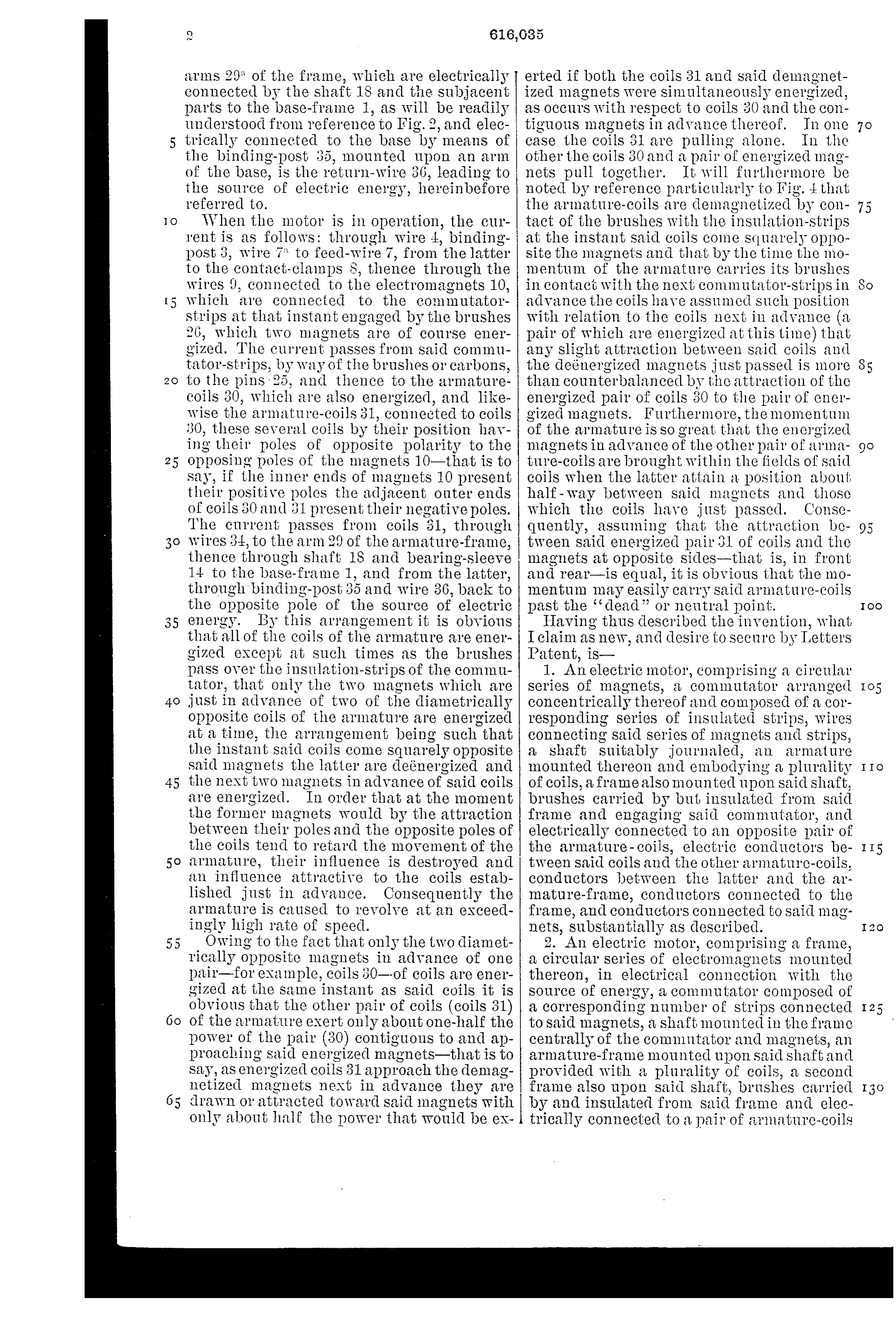
arms 29 of the frame, which are electrically erted if both the coils 31 and said demagnet connected by the shaft 1S and the subjacent ized magnets were simultaneously energized, parts to the base-frame 1, as will be readily as Occul's with respect to coils 30 and the con understood from reference to Fig. 2, and elec tiguous magnets in advance thereof. In One 7 O trically connected to the base by means of case the coils 31 are pulling alone. In the the binding-post 35, mounted upon an arm other the coils 30 and a pair of energized mag of the base, is the return-wire 30, leading to nets pull together. It will furthermore be the source of electric energy, herein before noted by reference particularly to Fig. 4. that referred to. the armature-coils are demagnetized by con O When the motor is in operation, the cur tact of the brushes with the insulation-strips 'ent is as follows: through wire 4, binding at the instant Said coils come Squarely oppo post 3, wire 7 to feed-wire 7, from the latter site the magnets and that by the time the mo to the contact-clamps S, thence through the mentum of the armature Carlies its brushes wires 9, connected to the electromagnets 10, in contact with the next commutator-strips in So which ale connected to the commutator advance the coils have assumed such position Strips at that instant engaged by the brushes with relation to the coils next in advance (a. 26, which two magnets are of course ener pair of which are energized at this time) that gized. The current passes from said commu any slight attraction between said coils and tator-strips, by Way of the brushes or carbons, the deemergized magnets just passed is more to the pins 25, and thence to the armature than counterbalanced by the attraction of the Coils 30, which are also energized, and like energized pair of coils 30 to the pair of ener Wise the armature-coils 31, connected to coils gized lmagnets. Furthermore, the momentum 30, these several coils by their position hav of the armature is so great that the energized ing their poles of opposite polarity to the magnetS in advance of the other pail of arma 25 Opposing poles of the magnets 10-that is to ture-coils are brought within the fields of said Say, if the inner ends of magnets 10 present coils when the latter attain a position about their positive poles the adjacent outer ends half-way between said magnets and those of coils 30 and 31 present their negative poles. which the coils have just passed. Conse The current passes from coils 31, through quently, assuming that the attraction be Wires 34, to the arm 29 of the armature-frame, tween said energized pair 31 of coils and the thence through shaft, 1S and bearing-sleeve magnets at opposite sides-that is, in front 14 to the base-frame 1, and from the latter, and rear-is equal, it is obvious that the mo through binding-post 35 and wire 36, back to mentum may easily carry said armature-coils the Opposite pole of the source of electric past the “dead or neutral point. OO energy. By this arrangement it is obvious Having thus described the invention, what that all of the coils of the armature are ener I claim as new, and desire to secure by Tetters gized except at such times as the brushes Patent, is paSS Over the insulation-strips of the commu 1. An electric motor, comprising a circular tator, that Only the two magnets which are Series of magnets, a commutator arranged just in advance of two of the diametrically concentrically thereof and composed of a cor opposite coils of the armature are energized responding series of insulated strips, wires at a time, the arrangement being such that connecting Said series of magnets and strips, the instant said coils come squarely opposite a shaft suitably journaled, an armature Said magnets the latter are detenergized and mounted thereon and embodying a plurality O 45 the next two magnets in advance of said coils Of coils, a frame also mounted upon said shaft, are energized. In Order that at the moment brushes carried by but insulated from said the former magnets would by the attraction frame and engaging said commutator, and between their poles and the opposite poles of electrically connected to an opposite pair of the coils tend to retard the movement of the the armature - coils, electric conductors be II5 50 allmature, their influence is destroyed and tween said coils and the other armature-coils, all influence attractive to the coils estab conductors between the latter and the ar. lished just in advance. Consequently the mature-frame, conductors connected to the almature is caused to revolve at an exceed frame, and conductors connected to said mag ingly high rate of speed. nets, substantially as described. 55 OWing to the fact that only the two diamet 2. An electric motor, comprising a frame, rically opposite magnets in advance of one a circular series of electromagnets mounted pair-for example, coils 30-of coils are ener thereon, in electrical connection with the gized at the same instant as said coils it is Source of energy, a commutator composed of obvious that the other pair of coils (coils 31) a corresponding number of strips connected of the armature exert only about one-half the to Said magnets, a shaft mounted in the frame power of the pair (30) contiguous to and ap Centrally of the commutator and magnets, an proaching Said energized magnets-that is to armature-frame mounted upon said shaft and Say, as energized coils 31 approach the demag provided with a plurality of coils, a second netized magnets next in advance they are frame also upon said shaft, brushes carried drawn ol' attracted toward said magnets with by and insulated from said frame and elec Only about half the power that would be ex- I trically connected to a pair of armature-coils
Page 6
located diametrically opposite each other, site any of said magnets, substantially as de electrical connections between said coils and scribed.
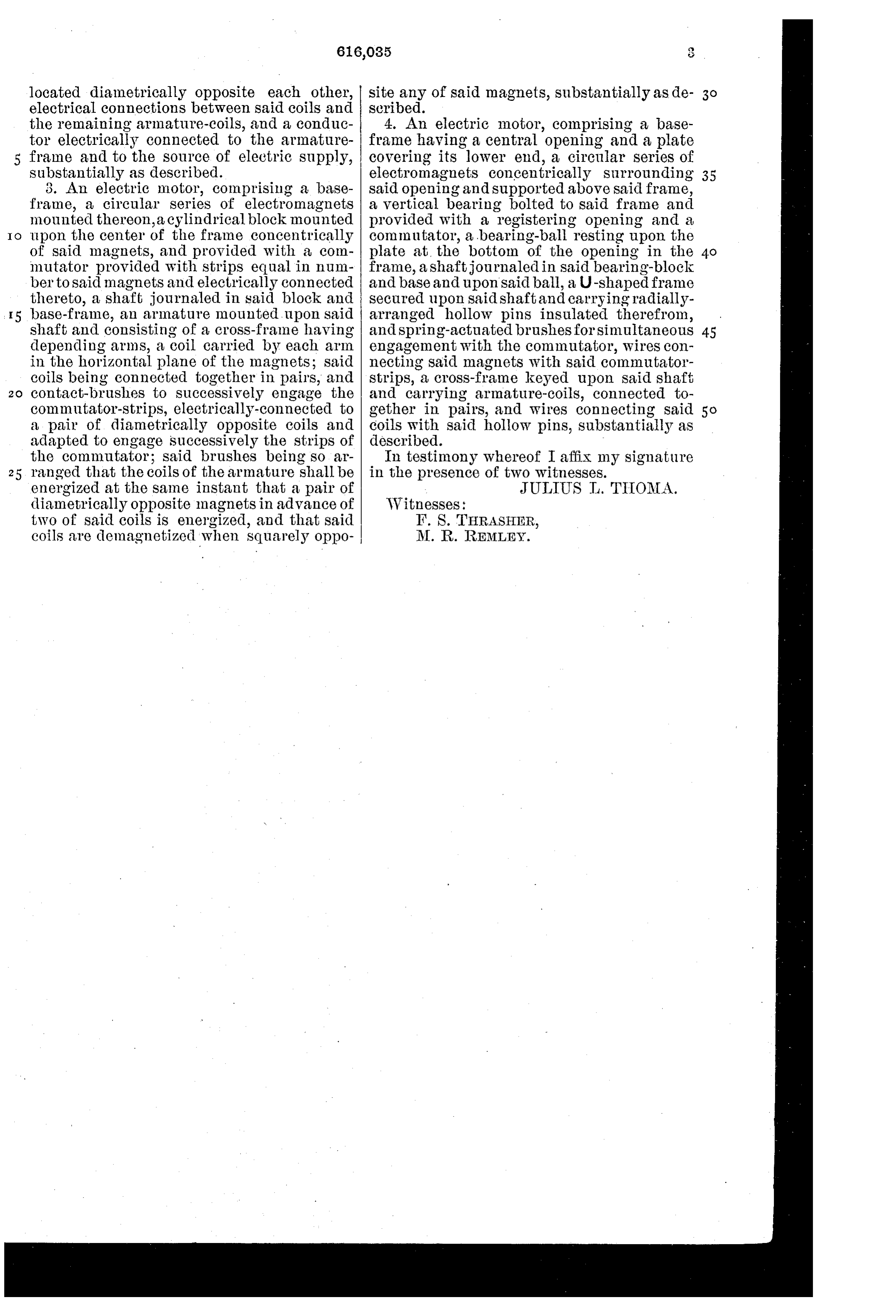
the remaining armature-coils, and a conduc 4. An electric motor, comprising a base tor electrically connected to the armature frame having a central opening and a plate frame and to the source of electric supply, covering its lower end, a circular series of substantially as described. electromagnets concentrically surrounding 35 3. An electric motor, comprising a base said opening and supported above said frame, frame, a circular series of electromagnets a vertical bearing bolted to said frame and mounted thereon, a cylindrical block mounted provided with a registering opening and a O upon the center of the frame concentrically commutator, a bearing-ball resting upon the of said magnets, and provided with a com plate at the bottom of the opening in the mutator provided with strips equal in num frame, a shaft journaled in said bearing-block berto said magnets and electrically connected and base and upon said ball, a U-shaped frame thereto, a shaft journaled in said block and secured upon said shaft and carrying radially base-frame, an armature mounted upon said arranged hollow pins insulated therefrom, shaft and consisting of a cross-frame having and spring-actuated brushes for simultaneous 45 depending arms, a coil carried by each arm engagement with the commutator, wires con in the horizontal plane of the magnets; said necting said magnets with said commutator coils being connected together in pairs, and strips, a cross-frame keyed upon said shaft contact-brushes to successively engage the and carrying armature-coils, connected to commutator-strips, electrically-connected to gether in pairs, and wires connecting said a pair of diametrically opposite coils and coils with said hollow pins, substantially as adapted to engage successively the strips of described.
the commutator; said brushes being so ar In testimony whereof I affix my signature 25 ranged that the coils of the armature shall be in the presence of two witnesses. energized at the same instant that a pair of JULIUS T. THOMA. (diametrically opposite magnets in advance of Witnesses:
two of said coils is emergized, and that said F. S. THRASHER, coils are demagnetized when Souarely oppo M. R. REMLEY.
Provenance
- Collection
- Cited prior art
- Original PDF
- patentimages.storage.googleapis.com →
- Pages
- 6
- Method
- pdftotext (the PDF's own text layer) + pdftoppm 300dpi page scans
- Source
- Google Patents bibliographic record
- Granted
- 1898-12-13
- Transcribed from
- patentimages.storage.googleapis.com →