patent · US3411574
Apparatus for transferring heat to and from a mass
19 November 1968
Page 1
Nov. 19, 1968 G . DE VRIES ET AL? 3,411 ,574 APPARATUS FOR TRANSFERRING HEAT TO AND FROM A MASS .
FIG. .
? NVENTORS.
GERRIT DE VRIES
H . EDMUND KARIS
BY GARY D . DRAGE
Roy MILLER ,
ATTORNEYS .
Page 2
United States Patent Office Pater 3 ,411 ,574
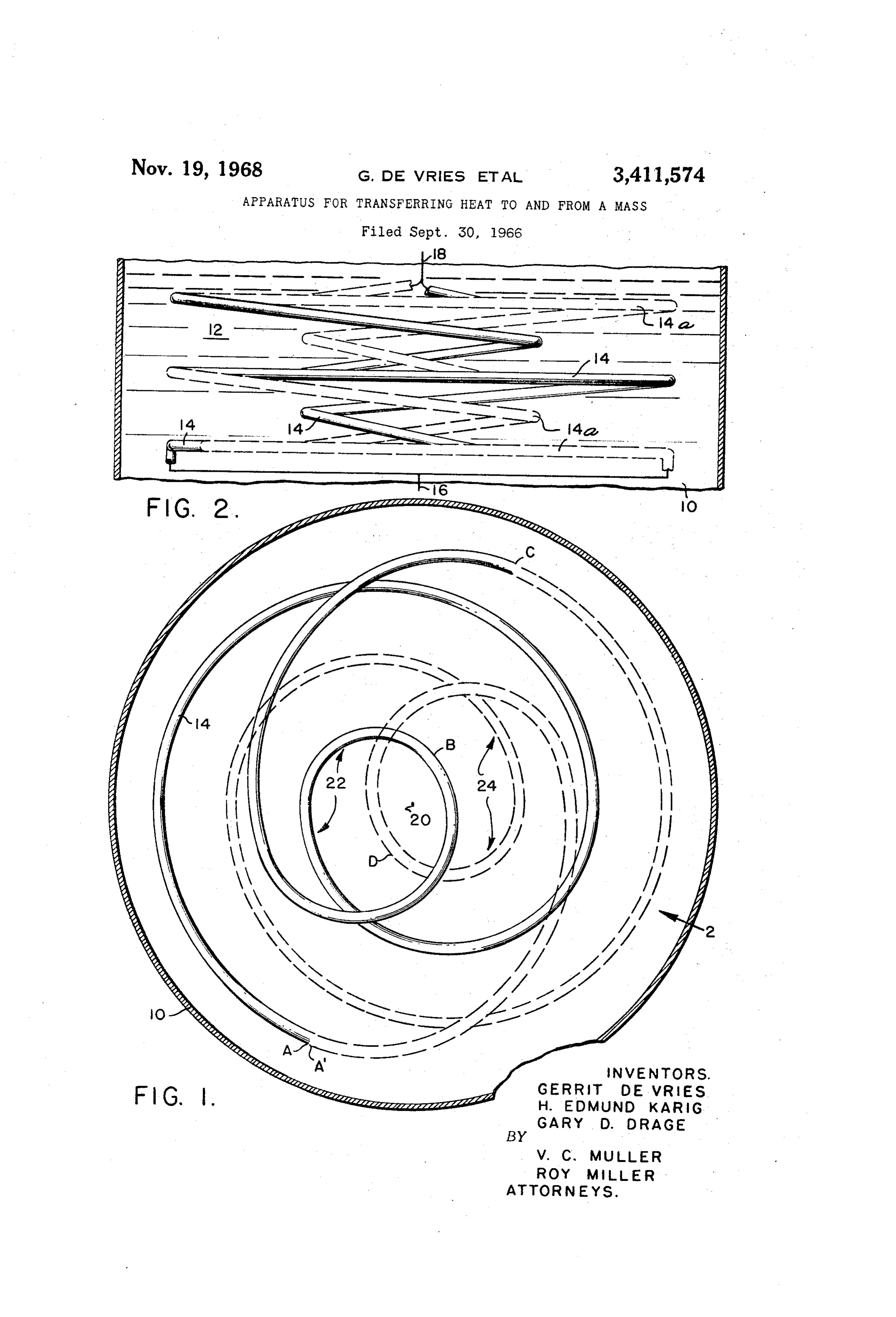
FIG . 2 is a vertical section as viewed in the direction 3 .411. 574 of arrow 2 , FIG . 1.
APPARATUS FOR TRANSFERRING HEAT TO The attainment of the objects is dependent upon certain AND FROM A MASS concepts and design parameters, the enumeration of
Gerrit De Vries and Gary , Altadena
D . Drage , Horace . Alhambra E . .Karig
, assignors to the, 5 which, at this point, will provide a better understanding
United States of America as represented by the Secre - of the invention to subsequently be described in detail: tary of the Navy ( a ) There must be more than one tube and each tube Filed Sept, 30 , 1966 , Ser . No. 584, 062 should be as equally spaced from another as possible , 6 Claims. (CI. 165 - - 145) ( b ) The tubes should fit the molten heat sink mass and 10 be uniformly distributed in it, ( c ) Each tube should be longer than the mass, par ticularly where a large number of small straight tubes is
ABSTRACT OF THE DISCLOSURE undesirable or the mass is of nonuniform cross section , Water tube type steam boiler in which a plurality of ( d ) The tubes should progress through the mass parallel connected angularly indexed identical tubes are 15 always from a cooler portion to a hotter portion , disposed in a molten salt bed, the tubes being so inter ( e ) All tubes should be identical in configuration , cross laced in layers to transfer heat uniformly from the salt section , and length , bed in progressive layers from bottom to top as the salt ( f ) The tubes should be interlaced so that at any zone bed solidifies . in the mass there is more than one heat extraction 20 circuit.
The invention described herein may be manufactured ( g ) For ease of fabrication , sharp bends in the tubing and used by or for the Government of the United States should be avoided .
of America for governmental purposes without the pay Referring now to the drawing and first to FIG . 2 , cylindrical container 10 , analogous to the container dis ment
Thisof invention any royalties thereon relates or therefor to steam . and more par - 25 closed in the application referred to , contains a molten boilers ticularly to improvements in boilers of the type disclosed salt or salt mixture 12 , in which is embedded a plurality in patent application of H . Edmund Karig and Gerrit of coils 14, 14a only two being shown for simplicity De Vries for Underwater Molten Salt Heat Storage Boiler, of disclosure but which may be any number desired . Both tubes are joined to a common feed water supply
application referred to , a steam boiler is dis - 30 16 at their lower ends and to a common steam outlet 18 closed for use in a steam propelled underwater vehicle, at their upper ends. The construction of coils 14 , 14a can best be under the boiler comprising a molten salt bed containing a steam stood by a description of the manner in which they are generating coil. As the coil extracts heat from the salt fabricated and assuming, first, that only one coil is bed it solidifies, first then progressively at the toward its bottom of the top . When salt bedsolidi completely , and- 35 employed . Referring to FIG . 1 and starting at point A .
fied and cooled to a temperature at which no more heat tube 14 is bent into the form of a flat spiral of decreasing may be ,extracted for generating radius of curvature about axis 20 for about 540° to perature superheated steam fromsteaman atavailable a desiredsteamtem point through. about
B From 360°point and
B toa point C it isspiral continuing inclined upwardly of increasing source is passed through the coil , remelting thesolidifica salt bed- 40 radius of curvature. At point C it starts a second flat and raising it to a desired temperature above solidifica- 40 spiral, parallel to the plane of the first flat spiral, con tion temperature and the steam generating cycle is tinuing (shown in phantom lines ) and thence with a repeated . The molten salt bed thus comprises a heat sink decreasing radius of curvature to point D , the extent of from which heat may be extracted for a period of time this portion also being about 540° . At point D it is after which heat must be added rs to the in whichheatheat sink ,isdiffer con - 45 again inclined upwardly through about 360° to a point A ', ing from supplied tinuously conventional boilers in which and continuously heat. For extracted is con sim - 40 spaced two planes above A , its point of beginning. The plicity of disclosure, the steam coil in such application astubedescribed is then bent into further pairs of adjacent coils , , until the entire stack is of desired height.
is illustrated as a single cylindrical helix and is claimed It will thus be apparent that the stack of coils consists broadly in combination with other boiler features . Itsinaalso 50 of repetitive sets, each set consisting of at least two flat alludes to a preferred type of steam coil comprising a spiraled coils disposed in spaced parallel planes , each coil plurality of parallel spaced flat coils each in the form ther ofas being spirally bent around the axis for about 540° and an Archimedean spiral which are connected together as joined by an inclined spiral portion extending about one continuous coil. As will subsequently appear , the pres 360° around the axis , the uppermost coil having a like ent invention relates to the specific construction andà 55 inclined portion for joining the beginning of the next arrangement of a plurality of interlaced coils of the type 50 set.
broadly alluded to in such application . Since one coil circuit would not satisfy the design One of the objects of the present invention is to provide parameters previously set forth , two or more identical a steam coil arrangement for use in a molten heat sink coil circuits are required . It will now be assumed that which will more uniformly extract heat from the sink 60 two circuits are desired . Two separate supplies of tubing in progressive layers from its bottom to its top. are fed to the bending machine with the two tubes dis Another object is to provide a plurality of coils, form posed together, thus forming two coiled circuits , as pre ing separate but parallel circuits which are interlaced in viously described in the bending of a single tube. ( This such manner that one circuit compensates for the tendency bending procedure is necessary since two or more coil of another circuit to nonuniformly extract heat from 65 circuits cannot be interlaced if bent separately . ) They the sink . are then rotated relatively 180° so that both tubes have Still further objects, advantages and salient features interlaced portions in each of the spaced planes. They will become apparent from the description to follow , the would appear in plan the same as in FIG . 1 with loop appended claims, and the accompanying drawing, in 22 axially misaligned with loop 24 in the first plane . which : 70 loops 22 and 24 again being axially aligned with their FIG . 1 is a horizontal section through a steam boiler next succeeding like loops in the third plane where they embodying the subject of the invention ; and again repeat themselves .
Page 3
If X number of tubes are desired , where X is 3 or more , (c ) said set comprising a plurality of separate tubes, two alternate modes of bending and indexing are possible forming separate parallel circuits and comprising a to interlace the tubes . In the first mode, and assuming number of layers , each tube being in the form of a for example , that 4 tubes are desired , the 4 tubes are plurality of parallel spaced spirals each disposed in fed together to the bending machine and bent in the 5 a spaced layer , the plurality of tubes being interlaced first layer as described for a single tube. They then rise and spaced apart in each layer, all tubes being of to the second layer with a loop , like 24 , misaligned 90° identical shape between a beginning and an end point, from the point of beginning ( instead of 180°) . In the at which latter its shape is repeated , the tubes being third layer the next loop is misaligned 180° and in the relatively rotated about said axis 360° divided by fourth layer it is misaligned 270°. After bending the 10 the number of tubes, the portions of the tubes dis tubes they are then indexed 90° relative to each other so posed in the spaced layers being substantially equi that in each layer there would be 4 loops like 22 and 24 distant from each other and so spaced from the outer forming a four leaf clover arrangement. In this mode envelope of said material, that heat is transferred of bending and interlacing the number of layers from a substantially uniformly between the material and the reference point of beginning to a point of repetition is 15 tubes in progressive layers perpendicular to said axis. equal to the number of tubes, X . 2 . Apparatus in accordance with claim 1 wherein the In the other mode of bending and interlacing, all of number of layers between said beginning and an end the tubes , say 4 , are fed to the bending machine in the point is equal to the number of tubes. same manner as described for two tubes ( loops 22 , 24 3 . Apparatus in accordance with claim 1 wherein the being misaligned 180° ) . They are then indexed 90° rela - 20 number of layers between said beginning and an end tive to each other. In this mode of bending and interlacing point is equal to 2 .
there are , again , four loops like 22 , 24 in each layer but 4 . Apparatus in accordance with claim 1 wherein each completion of all bending, before repetition , occurs in tube of said set is bent in the form of a flat helix and two layers rather than in four layers. In this mode of extending around said axis with decreasing radius of bending and interlacing, completion of all bending , be- 25 curvature to a point near said axis, the tube then con fore repetition , occurs in two layers regardless of the tinuing in increasing radius of curvature and upward in number of tubes . clination , crossing itself and forming a first loop , and With the exception of the specific coil circuits above continuing to the plane of the adjacent layer, and then described , the construction is the same as disclosed in continuing in the last named plane in another flat helix the identified application which includes a pressure 30 of decreasing radius of curvature to a point near said axis , equalizing tube communicating ambient pressure with the tube then continuing in increasing radius of curvature the space above the salt bed , suitable insulation around and upward inclination , again crossing itself and forming container 10 , and the necessary valves for connecting the a second loop axially misaligned from the first loop . coils to a steam supply when the salt bed is to be remelted . 5 . Apparatus in accordance with claim 4 wherein the Obviously many modifications and variations of the 35 loops of the successive layers are misaligned 360° di present invention are possible in the light of the above vided by the number of tubes. teachings. It is therefore to be understood that within 6 . Apparatus in accordance with claim 4 wherein the the scope of the appended claims the invention may be loops of the successive layers are misaligned 180°. practiced otherwise than as specifically described .
What is claimed is : 40 References Cited 1 . Heat exchange apparatus for use in a cylindrical UNITED STATES PATENTS vessel having a longitudinal axis and containing a sub stantially noncirculating material, the improvements, com 1, 382 ,670 6 / 1921 Price - - - - - - - - - - - - - - 165 - - 145 prising : 2 , 081,0435 / 1937 Kuhni - - - - - - - - - - 165 — 163
(a in) aparallel stack ofspaced hollowplanes coils perpendicular embedded in said material 45 3 , 163, 209 12 / 1964 Shinn - - - - - - - - - - - - - - 165 - 145 to said axis, (b ) said stack comprising a set of layers adapted to be ROBERT A . O 'LEARY , Primary Examiner. connected with a like identical set, CHARLES SUKALO , Assistant Examiner.
Provenance
- Collection
- Cited prior art
- Original PDF
- patentimages.storage.googleapis.com →
- Filed
- 1966-09-30
- Pages
- 3
- Method
- pdftotext (the PDF's own text layer) + pdftoppm 300dpi page scans
- Source
- Google Patents bibliographic record
- Granted
- 1968-11-19
- Inventors
- Vries Gerrit De; Horace E Karig; Gary D Drage; Navy Usa
- Transcribed from
- patentimages.storage.googleapis.com →