patent · US3812324
Glow coil ignitor
21 May 1974
Page 1 — bibliographic record
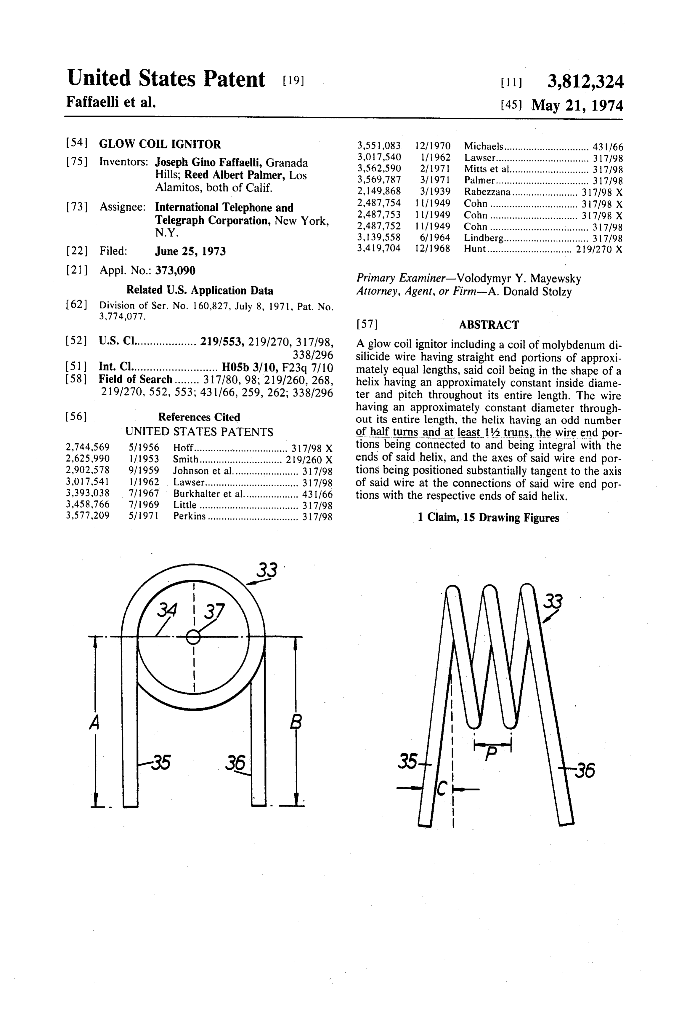
United States Patent (19) [11] 3,812,324 Faffaelli et al. (45) May 21, 1974 54 GLOW COIL. IGNITOR 3,551,083. 12/1970 Michaels............................... 43166 (75) Inventors: Joseph Gino Faffaelli, Granada 3,017,540
Lawser..... - - - - - - - - - - - - - - - - - - - - - - - - - - 317/98
Hills; Reed Albert Palmer, Los 3,569,787 3/1971 Palmer.................................. 317/98 Alamitos, both of Calif. 2, 149,868 3/1939 Rabezzana........................ 317198 X 73 Assignee: International Telephone and 2,487,754 l l l 1949 Cohn................................ 317/98 X Telegraph Corporation, New York, 2,487,753 l l 1949 Cohn................................ 317/98 X N.Y. 2,487,752 l l 1949 Cohn .................................... 317/98 3, 139,558 6/1964 Lindberg............................... 317/98 (22 Filed: June 25, 1973 3,49,704 l 2, 1968 Hunt............................... 219/270 X (21) Appl. No.: 373,090 Primary Examiner-Volodymyr Y. Mayewsky Related U.S. Application Data Attorney, Agent, or Firm-A. Donald Stolzy
52 U.S. Cl.................... 219,1553,219/270,317/98, A glow coil ignitor including a coil of molybdenum di 338/296 silicide wire having straight end portions of approxi 51 Int. Cl............................ H05b 3/10, F23.q 7/10 mately equal lengths, said coil being in the shape of a 58) Field of Search........ 317/80, 98; 219/260, 268, helix having an approximately constant inside diame 219/270, 552, 553; 431/66, 259,262; 338/296 ter and pitch throughout its entire length. The wire
having an approximately constant diameter through out its entire length, the helix having an odd number
UNITED STATES PATENTS of half turns and at least 1/2 truns, the wire end por 2,744,569 5/1956 Hoff.............."o p a s s a a 317/98 X tions being connected to and being integral with the 2,625,990 ll 1953 Smith.................... . . . . . . . . . . 2191260 X ends of said helix, and the axes of said wire end por 2,902,578 9/1959 Johnson et al........................ 317/98 tions being positioned substantially tangent to the axis 3,017,541 ll 1962 Lawser.................................. 317/98 of said wire at the connections of said wire end por 3,393,038 7|1967 Burkhalter et al.................... 431/66 tions with the respective ends of said helix. 3,458,766 7/1969 Little.................................... 317/98 3,577,209 5/197l Perkins................................. 317/98 1 Claim, 15 Drawing Figures
Page 2
Drawing sheet — no readable text.
Page 3
Drawing sheet — no readable text.
Page 4
Drawing sheet — no readable text.
Page 5
GLOW COIL GNTOR In the first place, it was not expected that protection against the MoSie wire breakage would result in provid
This is a division of copending application Ser. No. ing a MoSi wire wound in the shape of a helix. Al 160,827, filed July 8, 1971, now U.S. Pat. No. though this was unexpected, it has, in fact, been found 3,774,077. The benefit of the filing date of said co 5 that the MoSi wire, when wound in the shape of a he pending application is, therefore, hereby claimed for lix, actually is more self-protective from breakage due this application. to shock and vibration because the helix, even though BACKGROUND OF THE INVENTION the wire itself is still brittle, acts as a coiled spring. Thus, the brittle character of the wire which made it so
This invention relates to the art of heating a resistive O difficult to handle actually becomes an advantage when wire to the ignition temperature of a gas fuel, and more the wire is wound into a helix.
particularly, to a resistance wire ignitor having an ex Another outstanding advantage of the present inven ceedingly long life, mounting or shielding means there tion is that the wire, when wound in the shape of a he for, and a method of making the same. lix, acts as a spring which can give with differential In the past, it has been the practice to ignite the sur 15 thermal expansion and, therefore, eliminate breakage face burners and oven pilot burners of a gas range by thereupon due to the different thermal expansion coef placing a coil of platinum wire adjacent a burner, and ficients of the helix and its mountings. passing electric current through the wire of a magni Still another outstanding advantage of the MoSi. tude sufficient to heat the gas to its ignition tempera helix is that it need not be heated to a temperature as ture, high as that to which a straight MoSi, wire must be heated for reliable gas ignition. That is, the maximum
Unfortunately, all suitable materials including plati temperature num wire oxidize so badly in air that they have a useful helix for reliable required at the point thereof along the life while being continuously heated of only about 3 required of a single gas ignition is substantially below that days or less. straight wire. For this reason, oxi 25 dation is reduced and the MoSihelix of the present in
A wire made of molybdenum disilicide, MoSi can vention has a substantially longer life than any other re be heated to the gas ignition temperature by passing sistance wire ignitor including, but not limited to, a current therethrough. When so heated continuously in straight MoSi, wire.
air, the MoSi wire has a useful life of in excess of 1% Still another outstanding advantage of the present in years. However, MoSi, wire is very brittle and often 30 vention resides in the elimination of voltage regulation breaks due to differential thermal expansion with its equipment. In the past, when straight MoSi resistance mounts and with shock, pressure and vibration.
Until the present invention, it was thought that MoSi erate the wire atforsuch wires were used gas ignition, it was necessary to op an extremely high temperature wire was so brittle that it could not be made or used in any form other than that of a straight wire. This, in it 35 MoSig straight wire from was that voltage regulation required to prevent the melting down or falling to ig self, made the use of MoSi wire disadvantageous. Un nite the gas. Regulation thus prevented fortunately, such a wire, when employed as a resistance age to the straight wire from falling toothe far input volt due to an wire ignitor, must be heated to a maximum tempera increase in current through the ignitor wire caused by ture, usually midway along its length, which is very high a decline in the wire temperature. Wire temperature in order to provide reliable ignition of natural gas or the 40 could thus be reduced by ventilation and gas ignition like. The very fact that a high wire temperature was re thereby prevented.
quired when MoSi, wire was used in a resistance wire Reliable gas ignition by the MoSi helix maintained ignitor even limited the useful life of that ignitor. at a lower temperature than the straight wire has been Due to differential thermal expansion between a proven, wire temperatures in each case being measured MoSi, resistance wire ignitor and its mountings, expen 45 by the use of the same optical pyrometer. sive mountings were required. See U.S. Pat. No. The advantage regarding voltage regulation is out 3,569,787. standing because voltage regulation may be completely In addition to the foregoing, all the resistance wire eliminated by employing the MoSi helix. The cost of ignitors of the prior art required a large number of 50 special equipment required for voltage regulation in complicated and expensive component parts. the prior art has, therefore, been eliminated in accor SUMMARY OF THE INVENTION dance with the invention.
It will be noted that all of the advantages described
In accordance with the present invention, the above hereinbefore and some of the advantages described described and other disadvantages of the prior art are 55 hereinafter were simultaneously derived from the man overcome by providing a coiled wire made of MoSia. ufacture of a coiled MoSi wire helix. That is, not just Although it is unexpected, a way has been devised in one advantage was derived from this construction, but which the brittle MoSi wire can be wound into a helix a great many outstanding advantages were derived si of 2% turns, the helix pitch and diameter being con multaneously.
stant throughout its length. The wire has a circular 60 In accordance with another feature of the invention, cross section uniform throughout its length. The wire the helix extensions extend generally in one direction also extends beyond both helix ends the same distance, and are located in electrical connector cups integral the extensions both being straight, the axis of each ex with prongs for a male electrical plug. tension being tangent to the helix axis at its opposite Another feature of the invention resides in spot weld ends, 65 ing or otherwise bonding a brazing compound inside Employing the helix with the extensions, as just de each cup before the prongs and all of the metal struc scribed, and utilizing certain relative and/or absolute ture connected therewith are formed. Thus, the prongs dimensions extraordinary advantages are derived. are mounted vertical in an oven filled with an inert or
Page 6
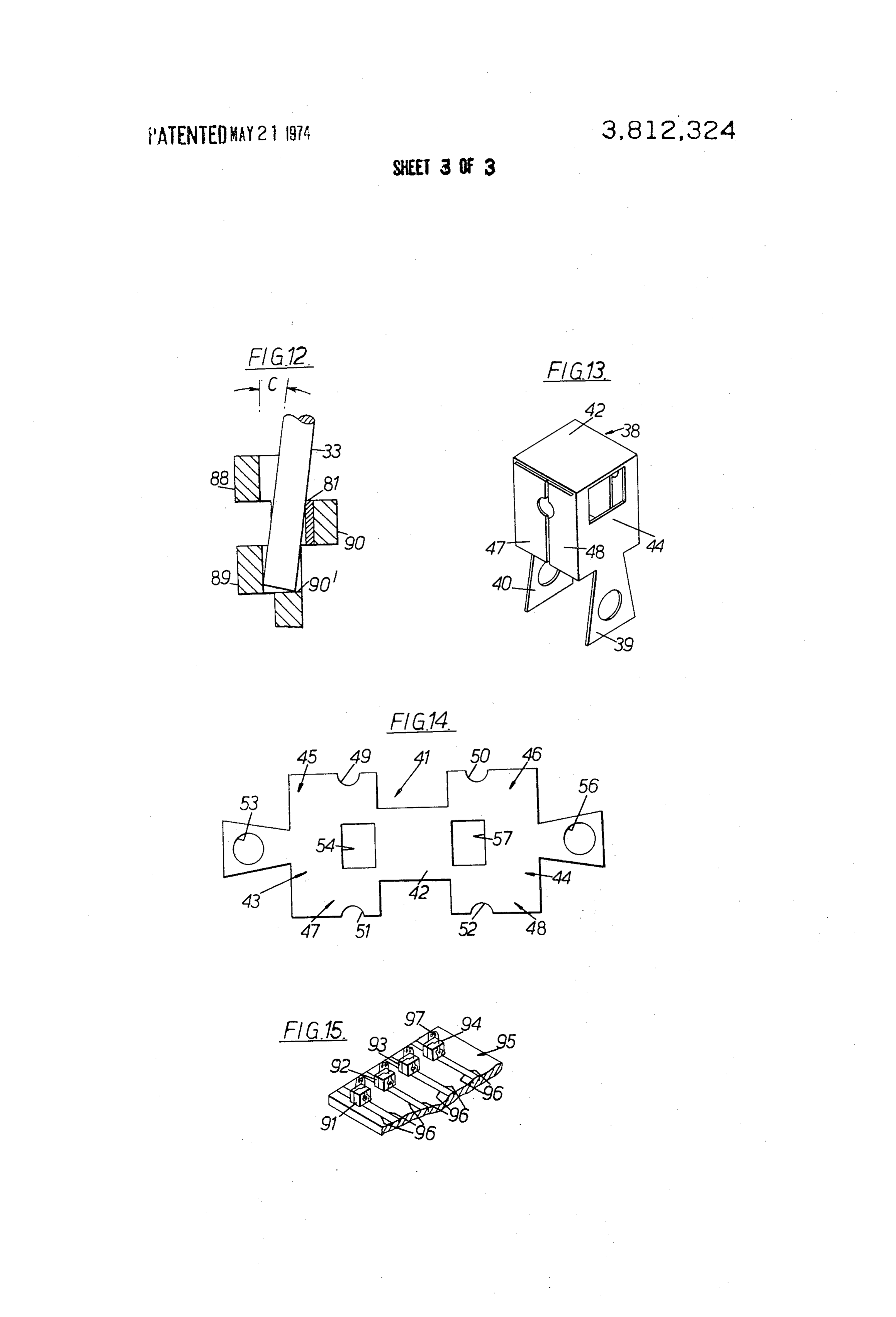
hydrogen gas or vacuum. A great many of the ignitors FIG. 10 is a greatly enlarged perspective view of a may thereby be batch brazed. The said helix extensions partial assembly of the present invention, the enlarge are mounted approximately vertically in the cups and ment being even greater than that shown in FIG. 6; flux applied to the helix extension and cup preparatory FIG. 1 is an elevational view looking at the assembly to mounting the substantially complete assembly in the of FIG. 10 from the front as viewed therein; oven. By this method, secure inexpensive mountings FIG. 2 is a vertical sectional view through the as are provided and bonded to the helix extensions. By sembly taken on the line 12-12 shown in FIG. 11; using the batch braze, the process is inexpensive. FIG. 13 is a perspective view of the shield disassem Another outstanding advantage of the present inven bled from the remaining portions of the ignitor of the tion is that the metal of portions integral with the O present invention;
prongs and the prongs themselves are made of 310 FIG. 14 is a top plan view of a metal stamping from stainless steel which has an annealing temperature which the shield of FIG. 13 is made; and about the same or somewhat below the brazing temper FIG. 15 is an assembly view of a plurality of ignitors ature of the brazing compound. without shields mounted on a refractory board prepara In accordance with the foregoing, the brazing step 15 tory to inserting the same into a hydrogen oven for per likewise produces an anneal which makes the prongs forming the said batch braze, the resistance wires in and their connections soft and pliable to further protect FIG. 15 not yet being brazed to their corresponding the brittle MoSi helix from breakage due to shock and electrical ignitors.
vibration, for example.
in accordance with the foregoing, the combined DESCRIPTION OF THE PREFERRED brazing and annealing step is economical. EMBODIMENTS
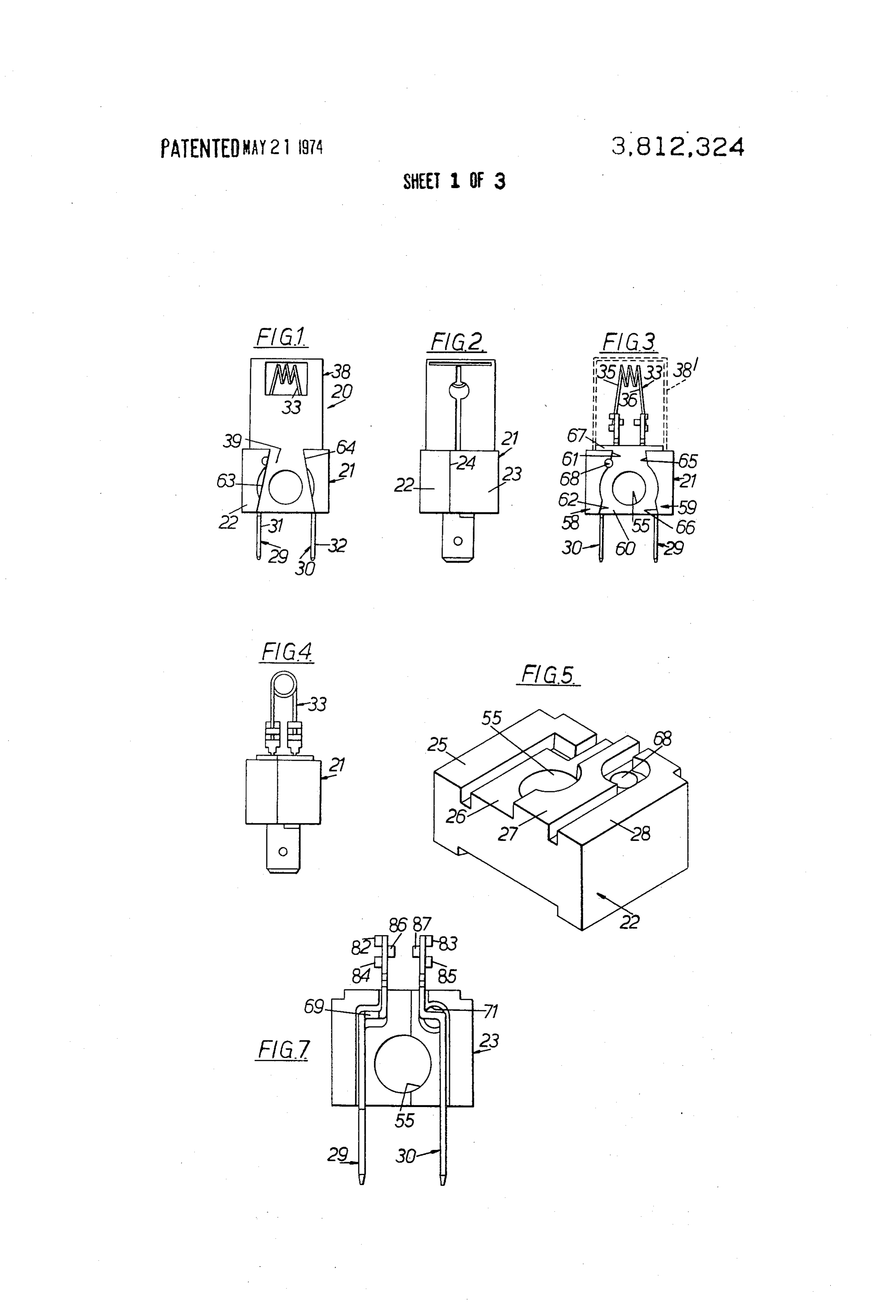
Still a further feature of the invention resides in the In FIG. 1, an electrical ignitor is indicated at 20 hav use of a necked down portion in the prongs to permit ing an insulator block 21 which may be used, more or the annealed, dead soft prongs to bend and thereby 25 less, as a base. Block 2 is split into two halves 22 and protect the brittle MoSi helix in the event of a severe 23, shown in FIG. 2, along a line 24. Line 24 appears shock. to be off center, and is, but blocks 22 and 23 are actu A further feature of the invention resides in the use ally identical. Their mating surfaces, however, are stag of a snap-on wind shield for the ignitor. This shield is gered. The mating surfaces are indicated at 25, 26, 27 made from a single metal stamping. It is thus very eco 30 and 28 in FIG. 5, only one of the halves of block 21 nomical to construct and to assemble. It requires no ad ditional parts whatsoever for assembly. That is, for ex beingAs shown in FIG. 5.
shown in FIG. 1, ignitor 20 electrical connectors ample, it requires no other fastening elements such as 29 and 30 which are made of 310 stainless steel. Con eyelets, screws, bolts, etc. nectors 29 and 30 extend completely through block 21, In accordance with the foregoing, the device of the 35 and are fixed in position relative thereto by means to present invention has a very small number of uncompli be described.
cated and inexpensive component parts. Connectors 29 and 30 have lower portions 31 and 32, The above-described and other advantages of the respectively, which may be plugged into a conventional present invention will be better understood from the electrical receptacle following detailed description when considered in con 40 resistance wire ignitorto33,supply shown electrical current to a in FIG, 1. Wire 33 is nection with the accompanying drawings, made of MoSi. It is shaped in the form of a helix with BRIEF DESCRIPTION OF THE DRAWINGS a constant pitch and a constant diameter throughout its entire
In the drawings, which are to be regarded as merely throughout length. Wire 33 is circular in cross section illustrative: its complete length, and has a diameter 45 constant throughout its complete length.
FIG. 1 is a front elevational view of a completely as As shown in FIG. 8, the helix portion of wire 33 be sembled electrical resistance wire ignitor constructed gins and ends in a plane perpendicular to the paper of in accordance with the present invention;
FIG. 2 is a side elevational view of the ignitor shown extensions 35through the drawing a line 34. To each end of the helix, and 36 are connected. That is, extensions in FIG, 1;
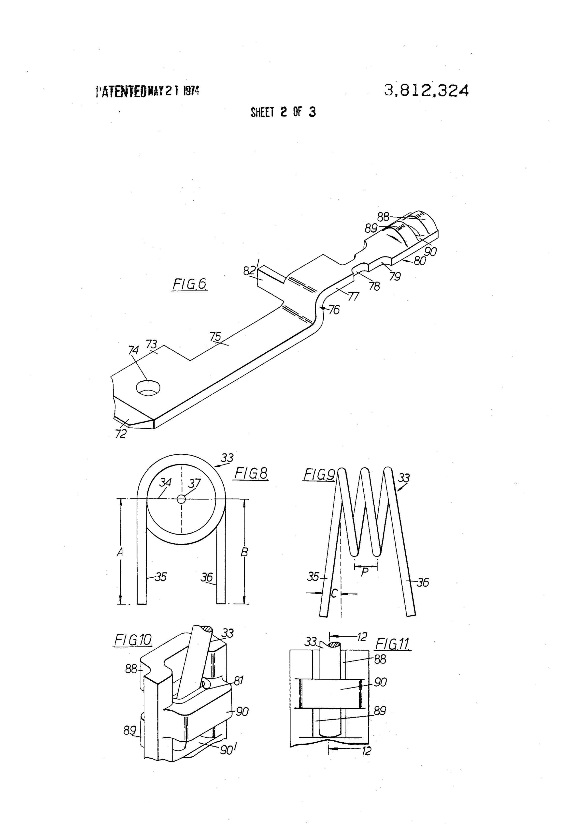
FIG. 3 is a side elevational view identical to that 50 35 and 36 are merely portions of wire 33 and thus are shown in FIG, 1 with only a portion of the ignitor shield integral with the portion thereof that is shaped in the shown therewith in dotted lines; form of a helix. Portions 35 and 36 have lengths A and FIG, 4 is a side elevational view of the assembly of B, respectively, where A is equal to B. Note will be FIG. 3 without any shield being shown therewith; taken that the axis of extension 35 is tangent to that FIG. 5 is an enlarged perspective view of half of an 55 portion of the axis of wire 33 which is shaped in the insulator block shown in FIGS. 1, 2, 3 and 4; form of a helix. The point of tangency is thus midway FIG. 6 is a greatly enlarged perspective view of an between the inner and outer diameters of the helix on electrical connector employed with the invention; each side of the helix axis 37 and at different points in FIG. 7 is an enlarged elevational view of an assembly 60 the said plane through line 34.
of the half of the insulator block shown in FIG. S with In FIG, 8, note will be taken that extensions 35 and two electrical connectors identical to that shown in 36, as viewed in FIG. 8, are absolutely vertical. How ever, this is not true in FIG. 9. Note that there is an
FIG. 8 is a greatly enlarged end elevational view of angle C with the vertical in FIG. 9that extension 35 the resistance wire of the present invention through 65 makes due to the fact that the helix has a finite pitch which current is passed to heat it up for gas ignition; and due to the fact that there is true tangency. The FIG. 9 is a side elevational view of the wire shown in angle C is of substantially more than just passing inter FIG, 8; est, and its importance will be described hereinafter.
Page 7
S 6
The ignitor 20, shown in FIG. 1, also has a shield 38 through, a first intermediate portion 75, a second inter which is hollow, substantially square in horizontal cross mediate portion 76, a third intermediate portion 77, a section, except for two projections 39 and 40, integral fourth intermediate portion 78, a fifth intermediate therewith and shown in FIG. 13. portion 79 and an assembly 80. The connector shown Shield 38 may be made from a single metal stamping in FIG. 6 is made from flat sheet stock. That is, both of flat sheet material of a uniform thickness. Such a connectors are made of 310 stainless steel of a uniform stamping is shown at 41 in FIG. 14. A panel 42 provides thickness throughout its area. However, in accordance the top of the shield 38, shown in FIG. 13. Also, the with one feature of the invention, a strip of brazing sides of shield 38 are identical. One side is provided by compound, shown at 81 in FIGS. 10 and 12, is spot panel 43, the other being provided by the panel 44. 10 welded or otherwise conventionally bonded to one side Two panels 45 and 46 enclose another side and panels of the sheet material from which the connector is 47 and 48 enclose still another side. Cutouts 49 and 50 made.
provide a substantially circular opening in panels 45 Each connector is provided with a projection 82", and 46, respectively, when the shield 38 is assembled. projection 69 being identical thereto. Similarly, cutouts 51 and 52 provide a circular opening 15 Another feature of the invention resides in the use of in panels 47 and 48, respectively, when the shield 38 is necked down portion 78 which, as will be described, assembled. when employed in a 310 stainless steel connector Panel 43 has circular and rectangular openings 53 which has been annealed dead soft, provides shock and 54, respectively, therein, circular opening 53 being proofing for the MoSi, wire 33.
of a diameter equal to that of a larger circular hole 55 20 Connectors 29 and 30 both have assemblies identical in block 21, shown in FIGS. 3, 5 and 7. Panel 44 has to assembly 80 and include, for example, as shown in circular and rectangular openings 56 and 57, respec FIG. 7, upper outside loops 82 and 83, lower outside tively, identical to openings 53 and 54, respectively. loops 84 and 85 and middle loops 86 and 87. Loops 82, Shield 38 may be snap fit on block 21. Block 21 has 84 and 86 are formed integrally with connector 29. bosses 58 and 59, shown in FIG. 3. The surfaces of 25 Loops 83, 85 and 87 are formed integrally with connec bosses 58 and 59, shown in FIG. 3, are flat and in the tor 30.
same plane, such plane being parallel to a flat surface Assembly 80, shown in FIG. 6, shows upper and 60. Boss 58 has straight portions 61 and 62 which are lower outer loops 88 and 89, respectively. However, a inclined with the same taper as the side edges of shield 30 small portion of a middle loop 90 may also be seen in projections 39 and 40, shown in FIG. 13. The taper is F.G. 6.
more evident between lines 63 and 64, in FIG. 1. Simi In order to better understand the views of FIGS. 10, larly, boss 59 has flat surfaces 65 and 66. The surfaces 11 and 12, inspection of the views of FIGS. 3 and 4 of portions 61 and 62 lie in a single plane which is dis should be made noting especially the relationship be posed at an angle relative to the single plane in which 35 tween the wire 33 and the "cup' ends of connectors 29 the surfaces of portions 65 and 66 lie. and 30 where loops 82-87 are located. Note that loops Block 21 has a boss 67 which is substantially square, 88,89 and 90 generally form a cup having a flat bottom and which fits inside shield 38 shown in phantom at 38' surface 90' where loop 89 has been broken out of the in FIG. 3. said sheet stock and where the lower end of wire 33 As shown in FIG. 3, block 21 has holes 68 and 71 on rests, as shown in FIGS. 10, 11 and 12. each side thereof. See also FIG.S. Hole 68 in FIG. 5 ex 40 A view of the left end of wire 33, as shown in FIG. tends completely through the half of the block shown 9, is shown in FIG. 8. A view of the right end of wire in FIG, 5. However, when two halves are assembled, as 33, shown in FIG. 9, would be identical to the view of shown in FIGS. 1, 2, 3 and 4, holes 68 and 71 do not FIG. 8. The offset of the halves of the block 21 pro become aligned. They do not lie in even partial regis 45 duces an offset in the locations of the upper ends of the tration. The hole 68 of the block half 22, not shown in connectors. Some further offset is provided because FIG. 7, extends around a connector projection 69 necked down portion 78 is not in the center of portion whereas insulator block half 23, shown in FIG. 7, has 77, shown in FIG, 6. The horizontal spacing evident in a hole 71 corresponding to hole 68 which has an axis FIG, 7 is simply produced because block 21 holds con that is horizontally displaced from the axis of the hole nectors 29 and 30 in that position, the corresponding 68, shown in FIG. 7. The hole 68thus has an axis about 50 holding slots for the connectors 29 and 30 being spaced midway between the vertical surfaces of projection 69 apart, which lie in planes perpendicular to the paper, as For clarity, the reference numerals used in FIG. 6 are viewed in FIG. 7. The axis of hole 71 is thus approxi also employed in FIGS. 10, 11 and 12. Note in FIGS. mately in the center thereof, spaced substantially more 55 10, 11 and 12 that loops 88, 89 and 90 generally form than a hole diameter from that of hole 68 from projec a cup to receive an end of wire 33. Comparing FIGS. tion 69. 3 and 9, note will be taken that, in the view of FIG. 3, In FIG. 5, note will be taken that surfaces 25 and 26 extensions 35 and 36 of wire 33 are disposed at the lie in the same plane. Similarly, surfaces 27 and 28 lie same angle C relative to a plane transverse to the helix in the same plane. However, the plane of surfaces 25 60 axis. This angle C is also shown in FIG. 12. Note that and 26 is parallel to and below that of surfaces 27 and in FIG. 3, the upper end of connector 29 is actually 28. closer to the viewer than the upper end of connector Connectors 29. and 30 are identical; however, they 30. This offset is provided, as aforesaid, by the offset in are oriented oppositely in FIG. 7. Further, only one the halves of block 21 and in the offset of necked down connector will be described because they are identical. 65 portion 78 from portion 77 of the connector shown in One such connector is shown in FIG. 6 having an end FIG. 6. The offset is desirable to be able to insert the portion 72 formed in the shape of a compound wedge, lower ends of wire 33 into the connector cups without a block portion 73 having a conventional hole 74 there stressing the wire 33. This not only prevents damage or
Page 8
breakage of wire 33 during assembly and during further steel connectors. Thus, the oven temperature is raised processing, but also provides a shock proof mounting to 1,800 F. for a period of about 5 minutes. The com for wire 33. pleted assemblies may be allowed to cool in air and are The reason for one offset is that wire extension 35 is ready for use immediately thereafter. However, a wind inclined downwardly, as viewed in FIG. 3, at the rear shield is helpful to keep the temperature of wire 33 of the helix, and extension 36 is inclined downwardly constant in use. Thus, after shield 38 is fabricated, as in front. Thus, the reason that extensions 35 and 36 are shown in FIG. 13, it can be simply snapped over insula offset in approximately perpendicular directions is that tor block 21 in the position shown in FIG. 2 with por extensions 35 and 36 are tangent to the helix portion tions 39 and 40 snuggly fitted in the channels defined of wire 33 at the ends thereof on opposite sides thereof. 10 between the surfaces of straight portions 61, 62,65 and 66 on both halves of the insulator block 21.
Notwithstanding the foregoing, it is an advantage Wire 33 may have any diameter, but preferably that, as shown in FIGS. 4 and 8, extensions 35 and 36 should be as small as possible for a high resistance, effi lie generally in vertical parallel planes tangent to an ex cient heating and low operating temperature. On the ternal cylindrical surface that outlines the helix. Thus, 15 other hand, if wire 33 is too small in diameter, it will be even though the end of wire 33 comes into the cup at even more likely to break due to any small shock or vi angle C, as shown in FIG. 12, looking at it the other bration. A wire diameter of 0.016 inch has been found way as in FIG. 11, it goes in straight and can thereby satisfactory and is preferable in the circumstances, make good contact with brazing compound 81, as The inside diameter of the helix, as shown in FIG. 8, shown in FIG, 12. 20 preferably is between about 0.12 inch and 0.13 inch, FIGS. 10, 11 and 12 actually illustrate an assembly The pitch of the helix, as indicated at P in FIG.9, pref. step in the method of the invention of making the igni erably is between about 0.036 inch and 0.046 inch, tor 20. In the manufacture of the invention, connectors The helix preferably has at least 1% turns and has an 29 and 30 are assembled in between block halves 22 odd number of half turns. However, at least 1% turns and 23, as shown in FIGS, 2 and 7. If desired, 25 have been found more satisfactory.
sauereisen or any other conventional refractory or in In accordance with the foregoing, it will be appreci sulator cement may be placed upon the surface facing ated that the helix inside diameter is preferably be the viewer in FIG. 7, tween about 7 to 9 times as large as the diameter of the With the block halves 22 and 23 and connectors 29 wire. Further, the helix pitch must be larger than the and 30 assembled and connectors 29 and 30 located in 30 wire diameter, and preferably is less than 3 times as the block grooves and in the positions shown in FIG. 7, large as the wire diameter, More efficient heating can cement may be inserted into holes 68 and 71, as shown be expected is these limits are retained. The same is in FIGS. 3 and 7, respectively. This step may be used true of lower wire temperature, with or without the previously described step of apply 35 Preferably, a voltage is applied between connectors ing cement. The same is true of the said previously de 29 and 30 which is adequate to heat one point on the scribed step, wire 33 to a predetermined temperature larger than the After the cement has dried, plugs 91, 92,93 and 94 temperature at any other point thereon, wherein said are "plugged into' a refractory board 95, as shown in predetermined temperature is between about 1,900 F. FIG. 15. Portions 31 and 32 and portions correspond and 2,400 F. Reliable ignition may then be achieved ing thereto, as shown in FIG. 1, thus extend down into 40 with a maximum wire life.
one of eight grooves 96 in board 95. The portion of Although a hydrogen oven has been described, it is board 95 between the closest immediate adjacent two to be understood that any oven may be employed. of the grooves 96 may be slightly wider than the space However, preferably, the oven is filled with an inert gas between portions 31 and 32 so that there is a tight or including, but not limited to, nitrogen. A vacuum may snug fit of the connectors on each side of the two im 45 also be used.
mediate adjacent grooves 96. Alternatively, each The phrase "inert gas" is hereby defined herein as in groove may be slightly thinner than the thickness of cluding a gas which does not react with the materials each of the portions 31 and 32 so as to allow for a snug placed in the oven in a deleterious way. or tight fit of the portions 31 and 32 in respective corre 50 Reduction may be anticipated if hydrogen is used. sponding slots 96. This is an advantage of hydrogen over some other After plugs 91, 92,93 and 94 have been plugged into gases. However, nitrogen may be used, if desired. Inert board 95, wires identical to wire 33 are then assembled gas is employed to reduce or eliminate oxidation. Oxi therewith as indicated, for example, at 97. Each end of dation can occur on the connectors 29 and 30, the the resistance wire of the MoSi wire ignitor is placed 55 brazing compound 81 and the wire 33. in a cup of a corresponding connector in the manner Due to the fact that the batch braze is performed at illustrated in FIGS. 10, 11 and 12. Now, brazing com an oven temperature of 1,800 F., a dead soft anneal of pound 81 is located contiguous to wire33, as shown in the connectors 29 and 30 is effected because the dead FIG. 12, This is true of the cup of each connector. High soft annealing temperature of 310 stainless steel is temperature brazing flux is applied to each cup area. 60 about 1,775 F.
Board 95 is then placed in a hydrogen or vacuum oven. The phrase "dead soft' is hereby defined herein as describing a material or metal which has been annealed
The composition of the brazing compound 81 is 18 to an extent such that it cannot be made any softer to percent nickel and 82 percent gold. A good bond could any substantial extent by any kind of further annealing. be made by raising the temperature of the oven to 65 about 1,800 F. However, there is another advantage Although board 95, shown in FIG. 15, may be made with the use of this temperature. The use of this tem of any desirable refractory material, insulating material perature causes a dead soft anneal of the 310 stainless or a material of a low specific heat, transite may be
Page 9
preferable because of its low specific heat. Further, the other hand, when the wire is formed into the helix, board 95 need not be made of a refractory material if the adjacent turns of the helix apparently heat each it has a low specific heat and will stand a temperature other and form a 'box' inside of which air or gas is of about 1,800 F. for about 5 minutes. heated efficiently. Moreover, the wire of the helix has Although outstanding features of the invention are a more uniform temperature along its length than does achieved by the use of wire 33 when it is formed at a a straight wire ignitor. That is, the temperature is not helix, many features of the invention are not limited to precisely uniform, but it is more uniform because of the this particular geometric configuration. mutual heating of adjacent turns. For this reason, the Wire ignitor 33 may be formed by heating it to a tem resistance between the connectors through the wire of perature between about 2,900 F. and 3,000 F. and O a MoSi helix varies much more linearly with tempera winding the same on a cylindrical carbon mandrel. ture. Self-regulation is thus produced which does not Preferably, both the wire and the mandrel are so require additional or more expensive apparatus for ac heated. Heating may be done by the use of three gas complishing voltage regulation. In other words, the torches located in positions equally spaced around the helix wire ignitor of the present invention with a con mandrel, the torches being located substantially in a 15 ventional low cost transformer may be substituted for single plane and directed radially inwardly toward the a MoSi straight resistance wire ignitor and a trans mandrel axis. former incorporating means for regulating the wire ig Another feature of the invention resides in the use of nitor voltage.
holes 53 and 56, shown in FIG. 14, in alignment with in accordance with the foregoing, it will be appreci hole 55. A bolt may be inserted therein for mounting 20 ated that although coiled resistance wire ignitors are purposes, if desired. old in the art, a great many outstanding advantages are The phrase "dead soft annealing temperature' is achieved by practicing the present invention and the hereby defined as that temperature above which a use of a MoSi helical resistance wire ignitor is not ob metal can be raised, but by the annealing thereof, it vious because no one suspected that it could ever be cannot be made any softer. 25 wound into a helix, MoSi being a very brittle material. The phrase "brazing temperature' is hereby defined It is so brittle, it may be broken with approximately the herein as that temperature to which brazing compound same force as used in breaking pencil lead for auto 81 or an equivalent thereof must be raised in order to matic pencils.
accomplish a suitable braze. Note will be taken that the brittle character of the In the brazing step, the use of flux may be helpful in 30 MoSi is, in fact, used because its brittle character attaining suitable wetting of the materials and in pre makes it a better spring and therefore, in the shape of venting oxidation, if desired. a helix, more shock and vibration resistant. Note will be taken that it is an outstanding advantage It is an outstanding advantage of the present inven of the invention that plugs 91, 92,93 and 94 may be tion that for reliable gas ignition, the peak temperature oriented, as shown in FIG. 15, with all of the connec 35 of the helical MoSi wire of the present invention is tors extending in an upward vertical direction to easily substantially lower than that of a straight wire. This hold the lower ends of the MoSi resistance wire igni means that the wire ignitor of the present invention has tors for the braze, yet holding the wire ignitors without a life longer than even a straight MoSi wire. stressing the same. It is an advantage of the present invention that the Wire 33, when it is first made straight, may be made 40 portions of connectors 29 and 30 above the portions by any conventional means or method and will be thereof identical to necked down portion 78 shown in found to have generally a resistivity of 100 ohm circu FIG. 6 and connected to wire extensions 35 and 36 lar mils per foot. It may be identical to Kanthal Super have a mass greater than that of wire 33. Thus, if con ST made by the Kanthal Corporation, if desired. The nectors 29 and 30 are dead soft, a shock will cause con voltage applied between connectors 29 and 30 will gen 45 nectors 29 and 30 to bend at the said necked down por erally be about 2.6 volts. With this voltage, when the tions thereof and protect wire 33 from damage or ambient temperature is approximately 70' F., the wire breakage.
will carry a current of approximately 3.6 amperes. What is claimed is:
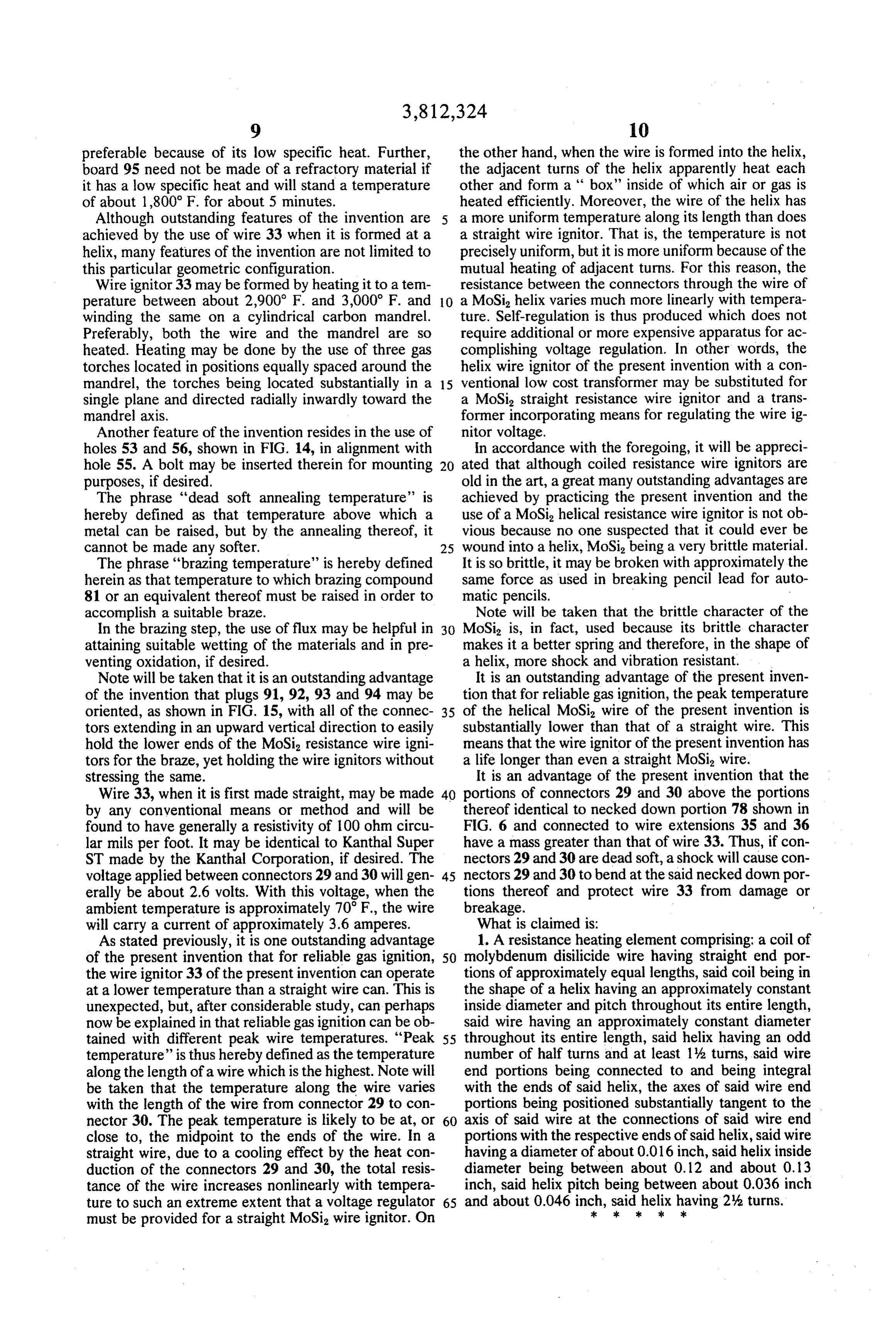
As stated previously, it is one outstanding advantage 1. A resistance heating element comprising: a coil of of the present invention that for reliable gas ignition, 50 molybdenum disilicide wire having straight end por the wire ignitor 33 of the present invention can operate tions of approximately equal lengths, said coil being in at a lower temperature than a straight wire can. This is the shape of a helix having an approximately constant unexpected, but, after considerable study, can perhaps inside diameter and pitch throughout its entire length, now be explained in that reliable gas ignition can be ob said wire having an approximately constant diameter tained with different peak wire temperatures. "Peak 55 throughout its entire length, said helix having an odd temperature' is thus hereby defined as the temperature number of half turns and at least 1% turns, said wire along the length of a wire which is the highest. Note will end portions being connected to and being integral be taken that the temperature along the wire varies with the ends of said helix, the axes of said wire end with the length of the wire from connector 29 to con portions being positioned substantially tangent to the nector 30. The peak temperature is likely to be at, or 60 axis of said wire at the connections of said wire end close to, the midpoint to the ends of the wire. In a portions with the respective ends of said helix, said wire straight wire, due to a cooling effect by the heat con having a diameter of about 0.016 inch, said helix inside duction of the connectors 29 and 30, the total resis diameter being between about 0.12 and about 0.13 tance of the wire increases nonlinearly with tempera inch, said helix pitch being between about 0.036 inch ture to such an extreme extent that a voltage regulator 65 and about 0.046 inch, said helix having 2% turns. must be provided for a straight MoSi, wire ignitor. On ck k se k
Page 10
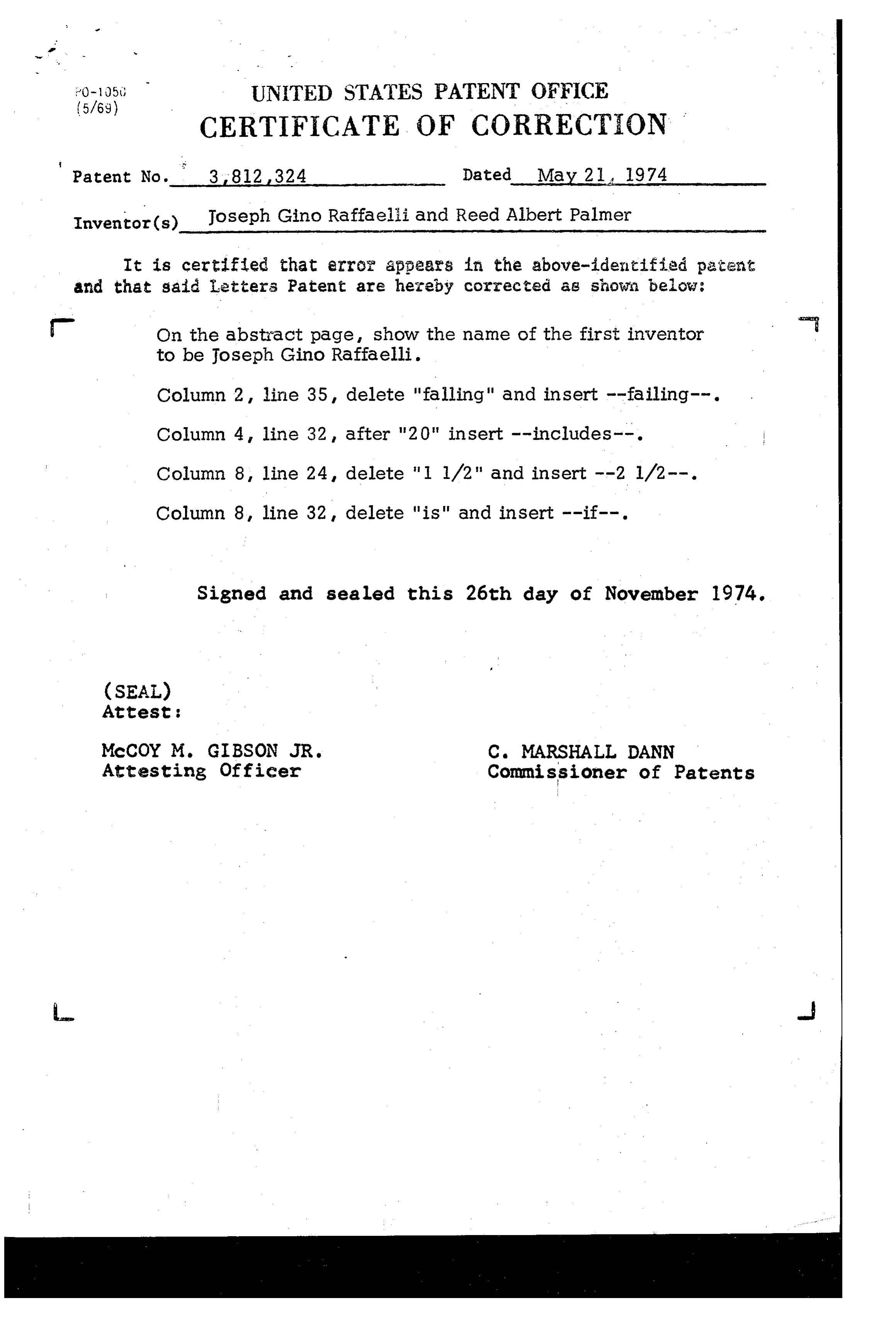
275" UNITED STATES PATENT OFFICE
CERTIFICATE OF CORRECTION
Patent No. 3.812,324 Dated May 21, 1974 Inventor(s) Joseph Gino Raffaeli and Reed Albert Palmer It is certified that error appears in the above-identified patent and that said i.etters Patent are hereby corrected as shown below: - On the abstract page, show the name of the first inventor to be Joseph Gino Raffaelli.
Column 2, line 35, delete "falling" and insert --failing--. Column 4, line 32, after "20" insert --includes--.
Column 8, line 32, delete "is" and insert --if--.
Signed and sealed this 26th day of November 1974.
(SEAL)
Attest :
Attesting Officer Commissioner of Patents
Page 11
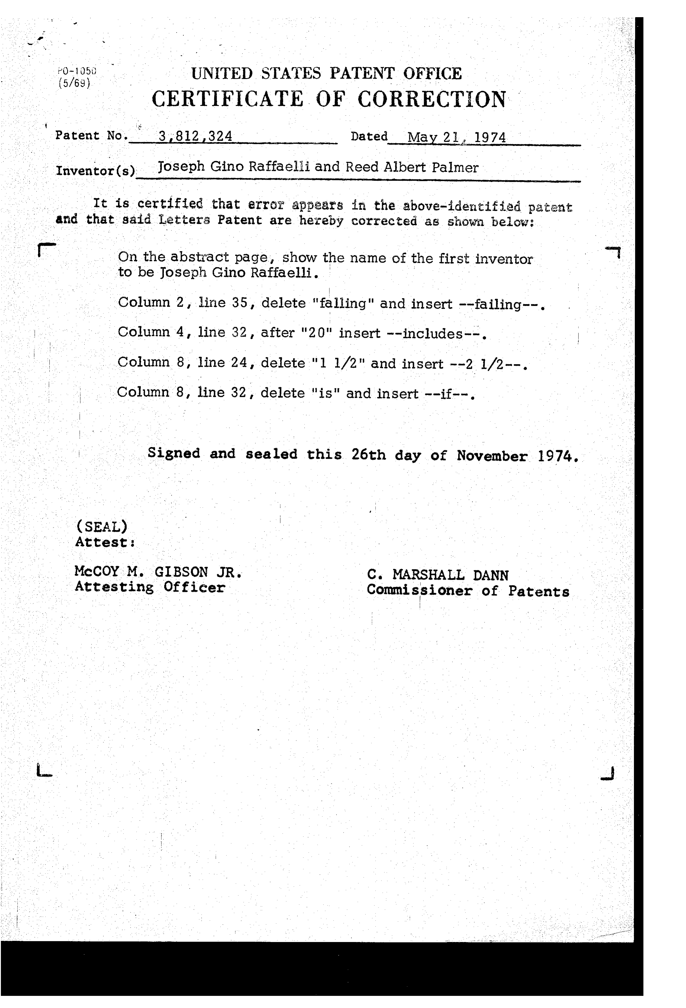
(5/69)05) UNITED STATES PATENT OFFICE
CERTIFICATE OF CORRECTION
Inventor(s) Joseph Gino Raffaelli and Reed Albert Palmer - It is certified that error appears in the above-identified patent and that said Letters Patent are hereby corrected as shown below: - On the abstract page, show the name of the first inventor to be Joseph Gino Raffaelli.
Column 2, line 35, delete "falling" and insert --failing--. Column 4, line 32, after "20" insert --includes--.
. . . . . Column 8, line 24, delete "l l/2" and insert --2 1/2--. Column 8, line 32, delete "is" and insert --if--.
Signed and sealed this 26th day of November 1974.
(SEAL)
Attest:
Attesting Officer Commi ssioner of Patents
Provenance
- Collection
- Cited prior art
- Original PDF
- patentimages.storage.googleapis.com →
- Filed
- 1973-06-25
- Pages
- 11
- Method
- pdftotext (the PDF's own text layer) + pdftoppm 300dpi page scans
- Source
- Google Patents bibliographic record
- Granted
- 1974-05-21
- Inventors
- J Faffaelli; R Palmer; Deutsche ITT Industries GmbH
- Transcribed from
- patentimages.storage.googleapis.com →