patent · US3182982
Infra-red wire annealing apparatus
11 May 1965
Page 1
Drawing sheet — no readable text.
Page 2
United States Patent Office 3,182,982 Patented May 11, 1965
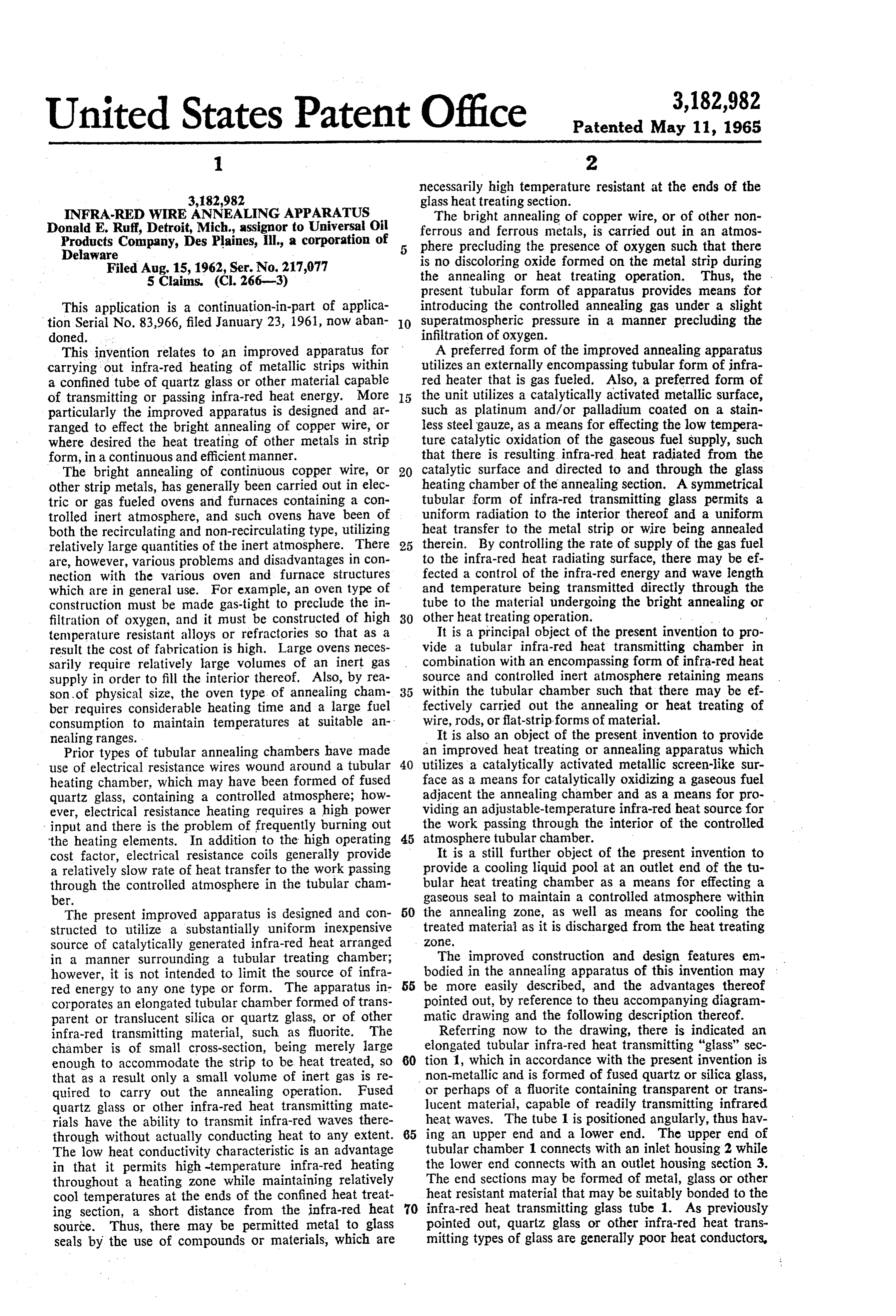
necessarily high temperature resistant at the ends of the 3,182,982 glass heat treating section.
NFRA-RED WIRE ANNEALING APPARATUS The bright annealing of copper wire, or of other non Donald E. Ruff, Detroit, Mich assignor to Universal Oil
Products Company, Des Plaines, Ill, a corporation of ferrous and ferrous metals, is carried out in an atmos 5 phere precluding the presence of oxygen such that there
Delaware is no discoloring oxide formed on the metal strip during Filed Aug. 15, 1962, Ser. No. 217,077 the annealing or heat treating operation. Thus, the . 5 Claims. (CI. 266-3) present tubular form of apparatus provides means for This application is a continuation-in-part of applica introducing the controlled annealing gas under a slight tion Serial No. 83,966, filed January 23, 1961, now aban 10 Superatmospheric pressure in a manner precluding the doned. infiltration of oxygen.
This invention relates to an improved apparatus for A preferred form of the improved annealing apparatus carrying out infra-red heating of metallic strips within utilizes an externally encompassing tubular form of infra a confined tube of quartz glass or other material capable red heater that is gas fueled. Also, a preferred form of of transmitting or passing infra-red heat energy. More 5 the unit utilizes a catalytically activated metallic surface, particularly the improved apparatus is designed and ar Such as platinum and/or palladium coated on a stain ranged to effect the bright annealing of copper wire, or less steel gauze, as a means for effecting the low tempera where desired the heat treating of other metals in strip ture catalytic oxidation of the gaseous fuel supply, such form, in a continuous and efficient manner. that there is resulting infra-red heat radiated from the The bright annealing of continuous copper wire, or 20 catalytic surface and directed to and through the glass other strip metals, has generally been carried out in elec heating chamber of the annealing section. A symmetrical tric or gas fueled ovens and furinaces containing a con tubular form of infra-red transmitting glass permits a trolled inert atmosphere, and such ovens have been of uniform radiation to the interior thereof and a uniform both the recirculating and non-recirculating type, utilizing heat transfer to the metal strip or wire being annealed relatively large quantities of the inert atmosphere. There 25 therein. By controlling the rate of supply of the gas fuel are, however, various problems and disadvantages in con to the infra-red heat radiating surface, there may be ef nection with the various oven and furnace structures fected a control of the infra-red energy and wave length which are in general use. For example, an oven type of and temperature being transmitted directly through the construction must be made gas-tight to preclude the in tube to the material undergoing the bright annealing or filtration of oxygen, and it must be constructed of high 30 other heat treating operation.
temperature resistant alloys or refractories so that as a It is a principal object of the present invention to pro result the cost of fabrication is high. Large ovens neces vide a tubular infra-red heat transmitting chamber in sarily require relatively large volumes of an inert gas combination with an encompassing form of infra-red heat supply in order to fill the interior thereof. Also, by rea source and controlled inert atmosphere retaining means son of physical size, the oven type of annealing cham within the tubular chamber such that there may be ef ber requires considerable heating time and a large fuel fectively carried out the annealing or heat treating of consumption to maintain temperatures at suitable an wire, rods, or flat-strip forms of material. nealing ranges. It is also an object of the present invention to provide Prior types of tubular annealing chambers have made an improved heat treating or annealing apparatus which use of electrical resistance wires wound around a tubular 40 utilizes a catalytically activated metallic screen-like sur heating chamber, which may have been formed of fused face as a means for catalytically oxidizing a gaseous fuel quartz glass, containing a controlled atmosphere; how adjacent the annealing chamber and as a means for pro ever, electrical resistance heating requires a high power viding an adjustable-temperature infra-red heat source for input and there is the problem of frequently burning out the work passing through the interior of the controlled the heating elements. In addition to the high operating 45 atmosphere tubular chamber.
cost factor, electrical resistance coils generally provide It is a still further object of the present invention to a relatively slow rate of heat transfer to the work passing provide a cooling liquid pool at an outlet end of the tu through the controlled atmosphere in the tubular cham bular heat treating chamber as a means for effecting a ber. gaseous seal to maintain a controlled atmosphere within The present improved apparatus is designed and con 50 the annealing Zone, as well as means for cooling the structed to utilize a substantially uniform inexpensive treated material as it is discharged from the heat treating source of catalytically generated infra-red heat arranged - ZOC.
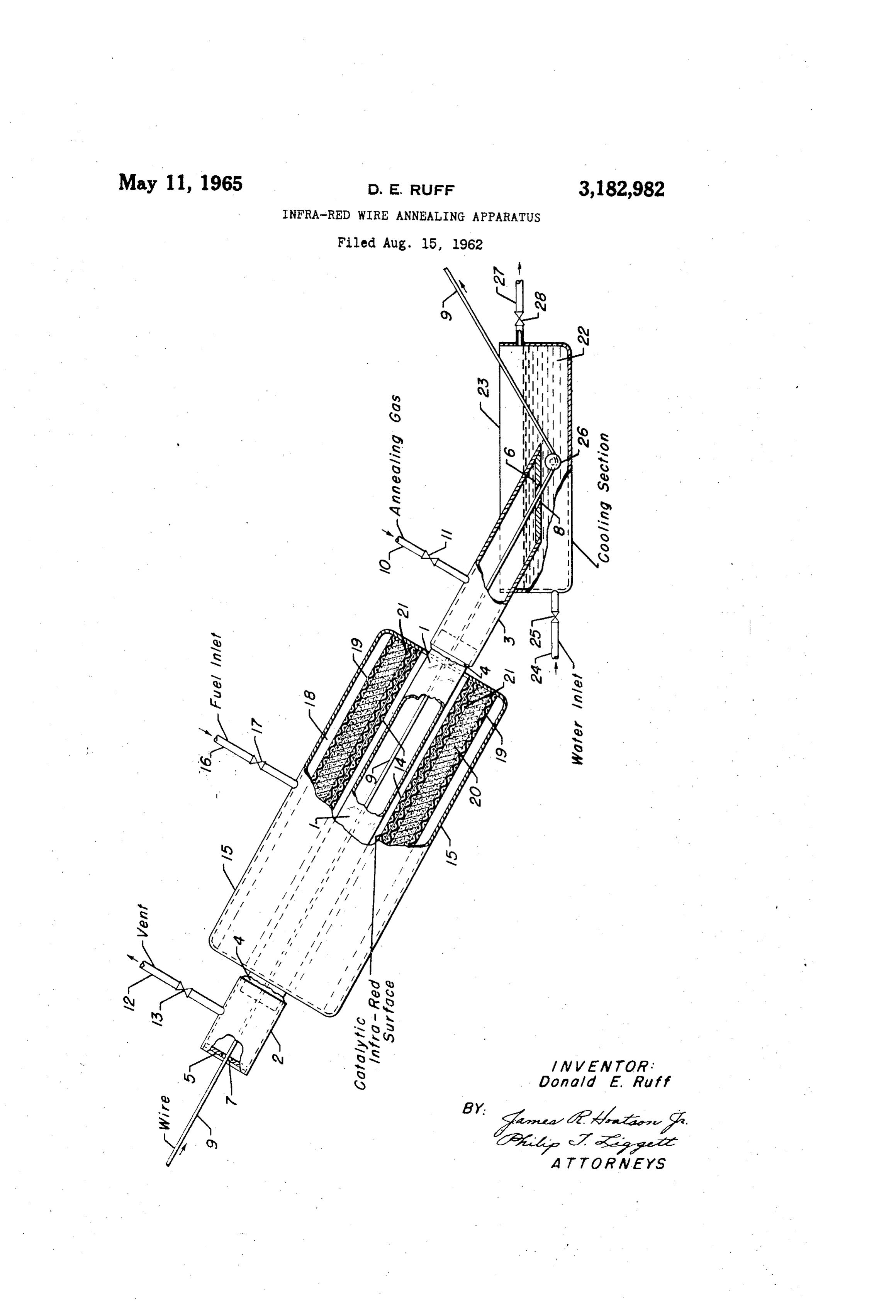
in a manner surrounding a tubular treating chamber; The improved construction and design features em however, it is not intended to limit the source of infra bodied in the annealing apparatus of this invention may red energy to any one type or form. The apparatus in 55 be more easily described, and the advantages thereof corporates an elongated tubular chamber formed of trans pointed out, by reference to theu accompanying diagram parent or translucent silica or quartz glass, or of other matic drawing and the following description thereof. infra-red transmitting material, such as fluorite. The Referring now to the drawing, there is indicated an chamber is of small cross-section, being merely large elongated tubular infra-red heat transmitting "glass" sec enough to accommodate the strip to be heat treated, so 60 tion , which in accordance with the present invention is that as a result only a small volume of inert gas is re non-metallic and is formed of fused quartz or silica glass, quired to carry out the annealing operation. Fused or perhaps of a fluorite containing transparent or trans quartz glass or other infra-red heat transmitting mate lucent material, capable of readily transmitting infrared rials have the ability to transmit infra-red waves there heat waves. The tube 1 is positioned angularly, thus hav through without actually conducting heat to any extent. 65 ing an upper end and a lower end. The upper end of The low heat conductivity characteristic is an advantage tubular chamber 1 connects with an inlet housing 2 while in that it permits high-temperature infra-red heating the lower end connects with an outlet housing section 3. throughout a heating zone while maintaining relatively The end sections may be formed of metal, glass or other cool temperatures at the ends of the confined heat treat heat resistant material that may be suitably bonded to the ing section, a short distance from the infra-red heat infra-red heat transmitting glass tube 1. As previously source. Thus, there may be permitted metal to glass pointed out, quartz glass or other infra-red heat trans seals by the use of compounds or materials, which are mitting types of glass are generally poor heat conductors,
Page 3
such that the ends of the tube extending beyond the packed between the screen 19 and the catalytically acti heating section may be sufficiently cool to permit the use vated member 14. The wool-like material 20 may com of sealing compounds which would not be effective when prise a heat resistant ceramic or mineral wool, or may used with highly conductive materials. The present draw be formed of a metal wool, such as steel wool. The ing indicates diagrammatically that the end sections 2 wool-like layer 20 is maintained in a multi-fold thick and 3 are attached to the tube 1 by a suitable sealing ma ness as compared to the catalytic screen or mesh 14 such i terial 4. The extremities of the end sections 2 and 3 that there is sufficient pressure drop to insure uniform are provided respectively with closure members 5 and 6 distribution of the gas fuel stream to the catalytic surface that are designed to maintain in a relatively gas-tight man 14, and such that there is sufficient thickness of insula ner a suitable incrt atmosphere within the interior of the O tion to preclude the radiation and transmission of heat heating tube . The closures 5 and 6 necessarily have from the radiant surface 14 to the gas distributing zone small central openings 7 and 8, respectively, in order to 8, whereby to in turn preclude, the chance of "back accommodate the passage of a wire or bar 9 through the flashing" and any explosion taking place at the fuel apparatus for heat treating purposes. The overall size Source. Also in a desired construction, at least one heat and shape of the openings 7 and 8 for each apparatus reflecting screen 21 may be incorporated into the infra will, of course, be modified to conform with the size and red heating unit so that there is an additional membrane shape of the wire passing through the heat treating ap effecting the reflection of heat outwardly from the cata paratus. lytic surface 14 and a diminishing of the chances of a In order to maintain a controlled substantially oxygen "backfire' to the fuel supply source. The screen mem free atmosphere in the heat treating section, nitrogen, 20 ber 21 may be positioned inwardly from and directly carbon dioxide, or other controlled composition gas is adjacent the catalyzed mesh 14. Although not shown continuously or periodically supplied to the tubular heat in the drawing, the pervious wool backing 20 may com ing section by means of an inlet line 10 and control valve prise one or more layers of different density wool-like 1. Where a continuous introduction is desired, the an material, or layers of different materials, such as a com nealing gas may be continuously discharged through out bination of ceramic wool and steel wool. Still further, let line 12, having control valve 13, which connects with in lieu of the wool-like material 20, the distributing layer the upper wire inlet section 2. This arrangement provides may comprise the use of two or more layers of fine and/or a countercurrent flow between the incoming gas stream medium mesh alloy screens. For example, a suitable and the downwardly moving wire 9 which is to be treated; heat reflecting and gas distributing media has been formed however, where desired, the annealing gas may be intro 30 of a combination of one 16-mesh screen along with two duced through line 12 and valve 13 and subsequently dis 40-mesh screens placed in back of or upstream from the charged through line 10, or through the wire openings coated screens, in the position of the material 20. 7 and 8. Although not deemed as desirable, an electrical coil Encompassing the tubular glass chamber 1, there is type of infra-red heat source may also be used to en provided in this embodiment an infra-red heater means compass the tube i, Varying shapes may bc used for the having a catalytically activated porous metallic surface infra-red heat emitting surface 14 and thc chamber 18. 4 suitable to effect the oxidation of a gaseous fuel and The present embodiment indicates diagrammatically a thus provide in turn a glowing flameless infra-red heat circular cross section catalyzed membrane 4 encompass radiating surface. A suitable catalytic coating for this ing a round tubular glass member 1. However, other purpose is that disclosed in the Suter and Ruff Patent 40 shapes may be utilized as, for example, a square or No. 2,720,494, issued October 11, 1955, that is, an alloy rectangular shaped infra-red surface, and the enclosing metal screen having platinum or palladium deposited chamber providing for the gas distribution to the catalytic thereon. As an example, a chrome-nickel stainless steel radiating surface may well be a similar shape, providing (Chromel or Nichrome) screen of approximately 40 a substantially uniform heat transmission to the inner mesh is precleaned by immersion in a hot surface active infra-red heating section. Means may also be provided agent, thoroughly rinsed with steam or hot water, and for moving or retracting the infra-red heat source from then subjected to plating by immersion or by electroplat around the tubular unit 1, with control means for stopping ing. Preferably a coating of platinum and/or palladium the infra-red heating when the wire or strip materialis is deposited by electroplating to a suitable well bonded stopped from its continuous passage through the heat coating of less than about 0.5 millimeter in thickness. treating section. A cylindrical heating unit hinged on After plating, the catalyst coating is thoroughly rinsed free one side and designed to open on an opposing side, may of soluble materials and is heated to a temperature above be used to operate in a "clam shell' type of action, with about 600 F. in an air stream containing volatile hydro means being provided to open and move back the heat carbons, such as hexane, in concentrations below the radiating surfaces responsive to means sensing a slowdown lower limit of explosibility, permitting surface combustion 55 or stoppage of wire undergoing heat treatment, in an to take place and effecting a conditioning and increased other type of arrangement, a U-shaped infra-red heater tenacity of the coating to the base metal. When in use, section may be retracted away from a substantially fixed the catalytically activated metal screen will effect the wall section which serves as a closure for the U-shaped flameless catalytic combustion of the fuel-air mixture portion of the heating section and a resulting tubular unit passing therethrough and give a high energy infra-red heat 60 when closed. In which case, automatic means may be source adjustable through a relatively wide temperature used to effect the movement of the U-shaped section away range. from the fixed wall closure section and from the glass There is indicated diagrammatically a housing or heat tube treating section. - ing chamber 15 of tubular form surrounding and enclos Also, as previously indicated, the present improved ing the inner catalytic surface 14. The chamber 15 is apparatus arrangement places the "glass' tubular mem adapted to receive a gaseous fuel from line 16, having ber and the movement of the wire therethrough in a control valve 17, and distribute it circumferentially to vertical or angular position, such that there is provided the backside or surface of the catalyzed member 4. The a lower outlet end for the wire passing therethrough. In fuel to the unit may be propane, butane, or mixtures the present drawing, in place of or in combination with thereof, natural gas, or other forms of light gaseous fuel, O the lower closure member 6, there is provided a liquid and is distributed within the chamber 15 throughout a cooling medium 22 within an open-topped container 23 substantially open annular-shaped fuel distributing sec which in turn encompasses and surrounds the lower end tion i8 and then passes uniformly at relatively low veloc portion of the annealing gas inlet section 3. The cooling ity through a gas distributing layer, such as screen 19 and liquid which may be water or other inert liquid with re a pervious wool-like material 20, which, as indicated, is spect to the metal being treated is introduced to the con
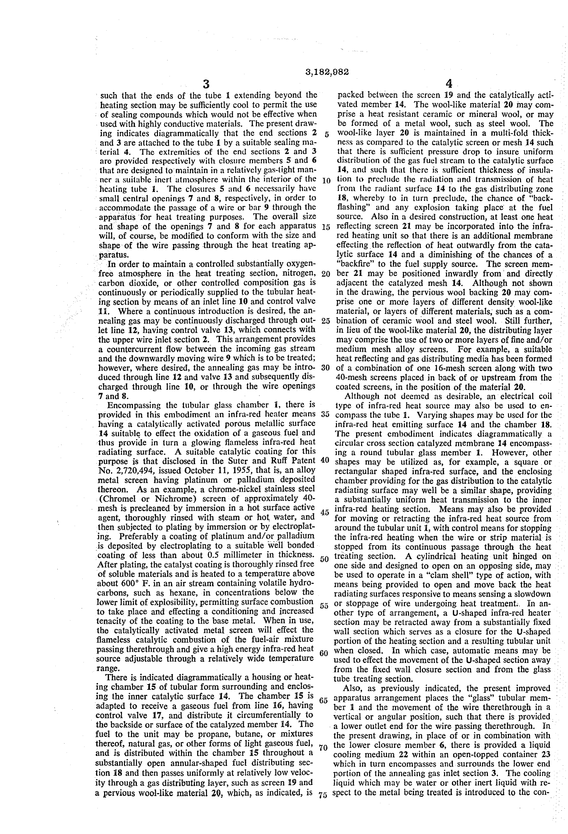
Page 4
tainer 23 by way of line 24 and valve 25 and is maintained a confined gaseous medium 6within said chamber, a con at sufficient depth and penetration into the lower end of tainer adapted to maintain a cooling liquid pool around the outlet section 3 such that a gas seal is maintained and within the lower end of said tubular chamber provid in the tubular heating section. The liquid seal may be ing thereby a gas seal means at the lower end of said used entirely in place of the closure member 6, or 5 channber and a cooling medium for contacting the wire alternatively, in combination therewith. strand being discharged from the lower end of said cham Suitable pulley or roller means 26 may be positioned ber following heat trcat ment therein, an annealing gas in the lower part of chamber 23 so as to suitably guide inlet at one end of said chamber, and a gas outlet from the wire 9 from the cooling liquid 22 as it is being con tinuously withdrawn from heat treating chamber 1 and 0. athecatalytically other end thereof, an infra-red heat source comprising activated metallic member encompassing cooling liquid 22. A liquid outlet line 27 and valve 28 substantially circumferentially said tubular chamber provides means for maintaining a given liquid level with whereby infra-red heat may be transmitted through said in chamber 23, particularly when there is a continuous chamber to said wire passing therethrough, and wire guide introduction of cooling liquid 22 into chamber 23. Vari means in the lower portion of said cooling liquid con ous shaped liquid retaining chambers may be utilized in 15 tainer for withdrawing the heat treated wire from the connection with the lower end of outlet section 3 and various types of pulley or guide arrangements may be pool. lower end of said chamber and from said cooling liquid used to pass the wire 9 through the cooling liquid cham 5. An infra-red annealing apparatus for effecting the ber, and it is not intended to limit the present invention bright to any one shape or design or arrangement in connection 20 phere, annealing of wire within a controlled inert atmos with providing the liquid at the outlet end and guiding quartz comprising in combination, a confined elongated glass tube positioned angularly to have an upper the wire therefrom.
I claim as my invention: end and a lower end, a closure member at the upper end 1. An infra-red annealing apparatus comprising in com to of said quartz glass tube having an aperture therethrough bination a confined tubular infra-red heat transmitting 25 in said accommodate the introduction of wire to be annealed chamber having opposing inlet and outlet ends adapted tain a cooling tube, liquid retaining means positioned to main to accommodate the passage of a material to be heat tube and providing liquid around the lower end of said glass treated, an infra-red heat source comprising a catalytically covering the lower end thereby a resulting liquid gas seal . activated metallic member substantially encompassing . annealing gas may be maintained of said tube, whereby an inert said chamber, gas seal means at each end of said chamber, 30 said therein, and whereby a gas inlet means at one end of said chamber and a gas cooling liquid contacts the wire being passed through outlet at the other end thereof providing an annealing glass said glass tube, an annealing gas inlet at one end of said gas atmosphere therein. - tube and gas outlet from the opposing end thereof, a catalytically activated alloy mctal screen positioned 2. The apparatus of claim 1 furthcr characterized in . around that said tubular chamber is positioned to have an upper providingandanspaced a short distance from said glass tube. infra-red heat source encompassing sub end and lower end, and the gas seal means at the lower stantially end of said tubular chamber comprises means for main red heat iscircumferentially said glass tube whereby infra taining a cooling liquid pool across such lower end where said wire passing therethrough, said transmitted through quartz glass tube to a layer of pervious heat by the material being heat treated in said chamber passes resistant and gas distributing material around said cata through said cooling liquid as it is discharged therefrom. 40 lytically activated screen and encompassing the latter, 3. An infra-red annealing apparatus comprising in com said material of multifold thickness relative to said cata bination, a confined tubular infra-red heat transmitting lytic screen and chamber having opposing inlet and outlet ends adapted uting layer and aproviding heat simultaneously a fuel distrib reflective material adjacent said to accommodate the passage of a material to be heat screen, a fuel receiving and distributing chamber encom treated, an infra-red heat source comprising a catalytically 45 passing activated metallic screen which is adjacent to and sub rial for both said catalytic screen and said pervious mate distributing fuel to the latter, fuel inlet means to stantially encompasses said tubular chamber, a gaseous said fuel receiving and distributing chamber, and wire fuel supply and fuel distributing means encompassing said guiding means within said cooling liquid retaining means catalytically activated screen and fuel inlet means to said distributing means whereby the oxidation of the fuel sup 50 for discharging said wire as it is continuously withdrawn plied to said screen by said distributing means provides from the lower end of said glass and said cooling liquid. infra-red heat energy for transmission through said tubu References Cited by the Examiner lar chamber to the material passing therethrough, gas seal UNITED STATES PATENTS means at each end of said tubular chamber, annealing gas inlet means at one end of said chamber and gas outlet 55 213,470?1 1/17 Finlay ?-------------------- 158-117.5 means at the other end thereof providing for the main 1,851,573 3/32 ElSey ---------------------- 266-3 tenance of an annealing gas atmosphere therein. 2,543,708 2/51 Rice et al. ------------ 148-16.7-? 4. An infra-red annealing apparatus adapted to effect 2,658,742 11/53 Suter et al. ------------ 266-3 X the bright annealing of wire within a controlled atmos 60 FOREIGN PATENTS phere and comprising in combination, a confined tubular 824,806 2/38 France. infra-red transmitting chamber positioned to have an 574,871 1/46 Great Britain.
upper end and a lower end, a wire inlet means at the upper end of said chamber adapted to pass a continuous MORRIS O. WOLK, Primary Examiner.
strand of wire into said chamber and substantially retain 65 RAY K. WINDHAM, Examiner.
Provenance
- Collection
- Cited prior art
- Original PDF
- patentimages.storage.googleapis.com →
- Filed
- 1962-08-15
- Pages
- 4
- Method
- pdftotext (the PDF's own text layer) + pdftoppm 300dpi page scans
- Source
- Google Patents bibliographic record
- Granted
- 1965-05-11
- Inventors
- Donald E Ruff; Universal Oil Products Co
- Transcribed from
- patentimages.storage.googleapis.com →