patent · US3729285
Burner and method of operating it to control the production of nitrogen oxides
24 April 1973
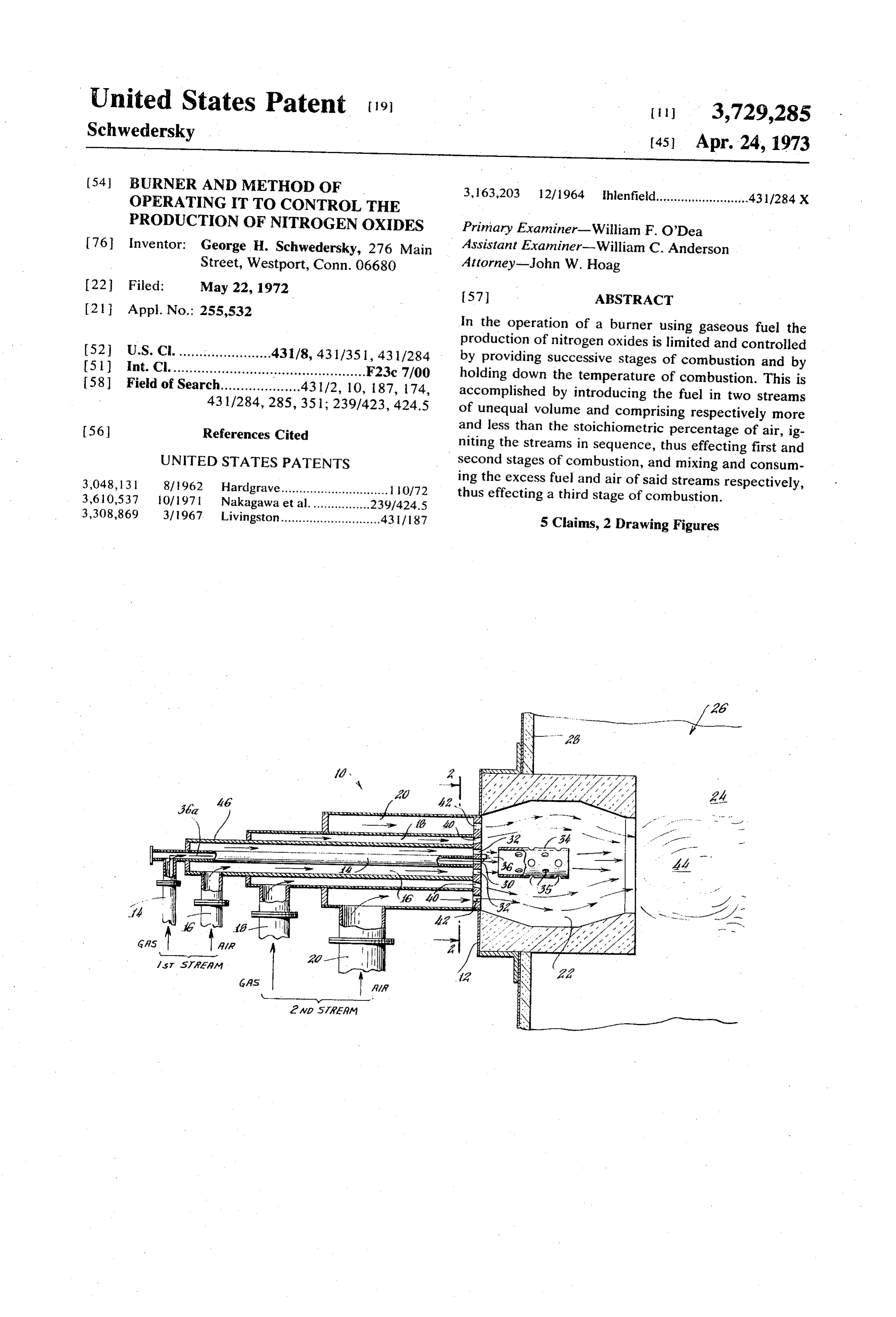
Page 1 — bibliographic record
United States Patent 19
Schwedersky (45) Apr. 24, 1973 54 BURNER AND METHOD OF 3, 163,203 12/1964 Ihlenfield..........................43 1/284 X
OPERATING T TO CONTROL THE
PRODUCTION OF NITROGEN OXDES Primary Examiner-William F. O'Dea
George H. Schwedersky, 276 Main Assistant Examiner-William C. Anderson Street, Westport, Conn. 06680 Attorney-John W. Hoag 22 Filed: May 22, 1972 57 ABSTRACT
In the operation of a burner using gaseous fuel the 52 U.S. Cl. .......................431/8, 43 1/351, 431/284 production of nitrogen oxides is limited and controlled (51) Int. Cl.......................... . . . . . . . . . . . . . . . . . . . . . . . F23c 7/00 by providing successive stages of combustion and by 58) Field of Search....................43 1/2, 10, 187, 174, holding down the temperature of combustion. This is accomplished by introducing the fuel in two streams 43 1/284, 285,351; 239/423, 424.5 of unequal volume and comprising respectively more 56 References Cited and less than the stoichiometric percentage of air, ig niting the streams in sequence, thus effecting first and
UNITED STATES PATENTS second stages of combustion, and mixing and consum 3,048,131 8/1962 Hardgrave.............................. 1 iO/72 ing the excess fuel and air of said streams respectively, 3,610,537 10/1971 Nakagawa et al.... - thus effecting a third stage of combustion. 3,308,869 3/1967. Livingston............................43 / 187 5 Claims, 2 Drawing Figures
Page 2
Drawing sheet — no readable text.
Page 3
BURNER AND METHOD OF OPERATING T TO
CONTROL THE PRODUCTION OF NITROGEN sponsored by American Gas Association, Inc. and In OXDES stitute of Gas Technology, held at Chicago, Ill., Feb. 28-Mar. 3, 1971, and particularly to Session IV, Paper
FIELD OF THE INVENTION 2, and the curve which is shown on page 20 of that This invention relates to a burner of the kind in Paper and is identified as FIG. 7..., Variation of Nitrogen which propane gas or other gaseous fuel is combined Oxides Concentration with Stoichiometry for a with air and burned to provide heat, as for example to Premixed Natural Gas/Air Flame consuming 200 Stan provide steam in an electric power generating plant. dard. Cubic Feet Per Hour of Gas, indicates that the maximum production of nitrogen oxide occurs when a
The invention is particularly directed to the method of percent of air slightly in excess of the optimum amount operating such a burner to limit and control the amount of air for combustion, about 107 percent of of nitrogen oxides which are produced while obtaining stoichiometric air, is mixed with the gaseous fuel, and substantially complete and therefor efficient com that the production of nitrogen oxides falls off rapidly bustion.
15 when the percentage of stoichiometric air by volume is
SUMMARY OF THE DISCLOSURE further increased, or is decreased. The curve indicates that when the gas/air mixture burned comprises ap
In accordance with this invention the production of proximately 107 percent of stoichiometric air by nitrogen oxides is kept at a low level by providing suc volume the accompanying production of nitrogen ox cessive stages of combustion, each occurring at a tem 20 ides is 120 parts per million by volume, dry basis, perature substantially less than would be obtained in a whereas when 140 percent of stoichiometric air is em single stage of combustion using the same volume and ployed the nitrogen oxides concentration falls to ap proportion of gaseous fuel/air. Instead of injecting proximately 80 parts per million by volume. Similarly gaseous fuel and air into the burner to mix and provide the curve indicates that if only 90 percent of a single stream in which for efficient heating the per 25 stoichiometric air by volume is present in the gas/air centage of air would be the optimum for obtaining mixture production of nitrogen oxides falls to approxi complete combustion of the gaseous fuel, the gaseous mately 70 parts per million by volume. fuel and air are introduced so as to form two separate In order to reduce the temperature at the time of ig streams of different volume and each comprising dif nition and thereby substantially reduce the production ferent ratios of gaseous fuel to air. One of the streams 30 of nitrogen oxides I have employed the information in comprises an excess of air and the other stream com dicated by the said curve to limit and control the prises an excess of gaseous fuel. One of the streams is production of nitrogen oxides and at the same time ob first ignited effecting a first stage of combustion. It then tain an efficient and substantially complete com ignites the second stream effecting a second stage of bustion. In order to accomplish this, instead of in combustion, and a third stage of combustion is pro 35 troducing into the burner a single mixture of gas and vided by the mixing and burning of the excess gaseous air, in accordance with my method two mixtures of fuel in one of the streams with the excess air in the gaseous fuel and air are introduced separately into the other of the streams. The temperature created in each burner and ignited in sequence. One of the gaseous stage is less than would have been created if the same 40 fuel-air mixtures comprises substantially more than 100 volumes of gas and air had been mixed and consumed in a single stage, but the total of heat produced is sub percent
of stoichiometric air and the other gaseous mixture comprises substantially less than 100 stantially the same as would have been produced in a percent of stoichiometric air. The first mentioned mix single combustion stage. ture therefor comprises a substantial excess of air and The invention will be best understood if the following 45 the second gaseous fuel-air mixture comprises a sub description is read in connection with the drawing in stantial excess of gaseous fuel. When the two streams which:
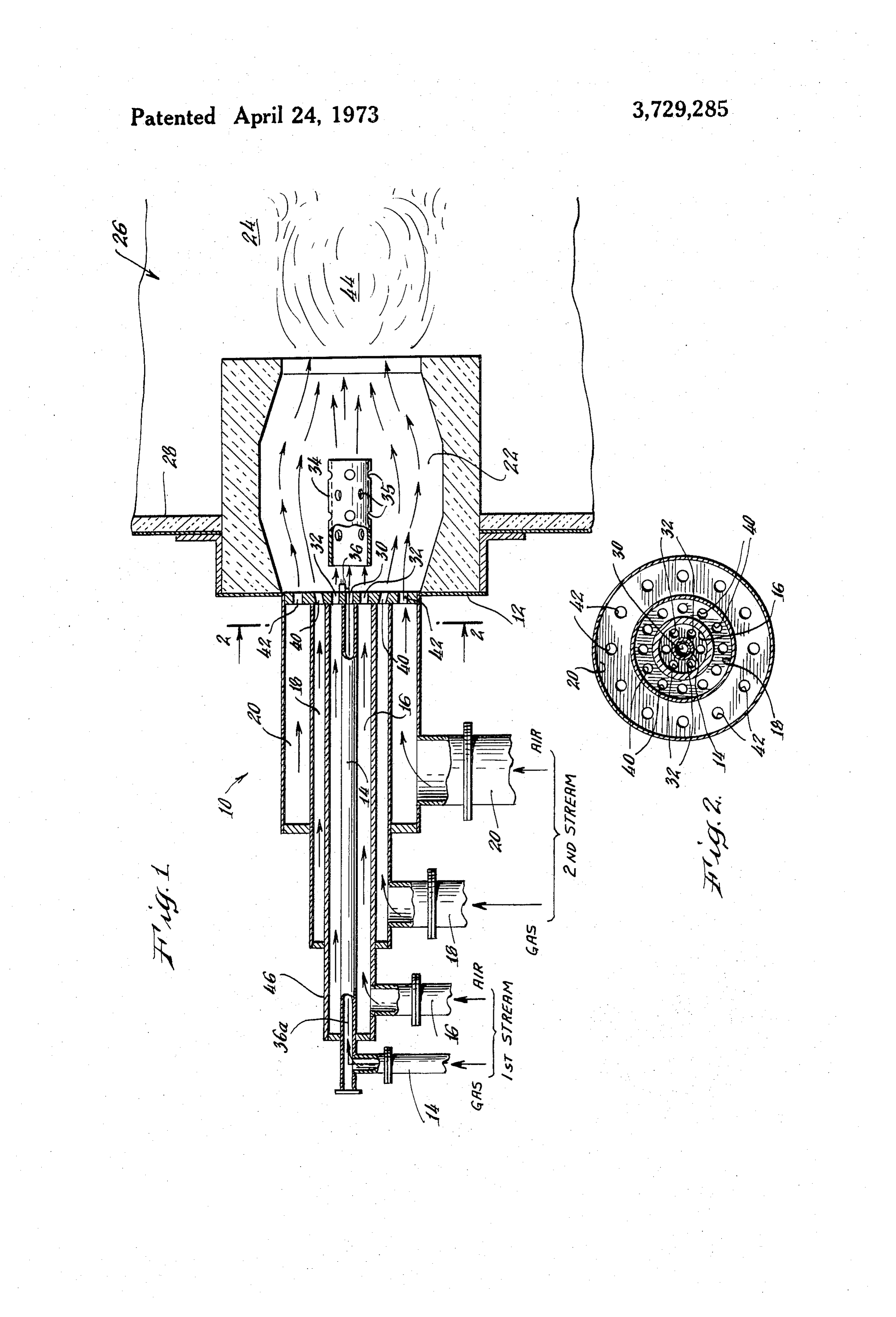
FIG. 1 is a side elevation showing a burner having substantiallythe are ignited temperature produced by each will be less than the temperature produced by ig two sets of gas and air inlets disposed to provide two niting a single gaseous fuel-air stream having the separate gaseous fuel/air mixture streams and means 50 volume of the combined two streams, and comprising for igniting them, and the excess air from one stream 100 percent of stoichiometric air. The temperature and the excess gaseous fuel from the other stream, in close to the burner face is therefor greatly reduced, the sequence providing a cascading three stage com exact amount of reduction varying to some extent de bustion, and pending upon the gaseous fuel employed. FIG. 2 is a vertical section taken on the line 2-2 of 55
FIG. With a single stream of gaseous fuel/air, if the ratio is the optimum for obtaining complete combustion, the
DESCRIPTION high flame temperature realized at the burner will fall Great difficulty has been experienced in attempting of off gradually as the gases travel to the flue. In the case
to reduce the amount of nitrogen oxide produced in comprise the two streams which are ignited in succession and the same total volume of gaseous fuel/air as a air-gas burners. It is well established by experiments single stream, that the production of nitrogen oxides is highest when the burner facetheis flame temperature initially adjacent lower because of the excess air and the mixture of gaseous fuel and air employed is close to the optimum mixture for combustion, or, in other 65 excess the fuel in the two streams, but the temperature of gases is sustained by the combustion in the second words close to the point where the temperature of com and third stages, bustion is the highest. Reference to the Proceedings, tially the same asand that temperature will be substan that of the single stream when the
Conference on Natural Gas Research and Technology, gases of the two streams reach the furnace flue and
Page 4
therefor the total transfer of heat is essentially the be injected into the choke collar 34. The burner tile is
By properly proportioning the volume of the two shaped so as to bring the excess fuel into the center gaseous fuel/air mixtures and the ratio.of gaseous fuel stream thus mixing it with the excess air causing them to burn and thus release, all of the heat from the fuel to air in each mixture the excess of air in one of the supplied in the two streams. mixtures can be proportioned to the amount of excess It will be understood that if desired the two streams fuel in the other of the mixtures so that during the three of gaseous fuel/air may be premixed before entering stages of combustion complete or substantially the burner.
complete combustion will be realized and a total The conduits 14 and 16 may be employed to provide production of heat obtained equal to, or substantially O a constant minimum supply of gaseous fuel and the equal to the amount of heat which can be obtained conduits 18 and 20 may be controlled to increase the from a single stream of gaseous fuel equal in volume to fuel supply as may be desired. the gaseous fuel in the two streams and mixed with 100 To illustrate my method more specifically I prefer to percent of stoichiometric air, the essential difference 5 use two mixed streams of gaseous fuel/air which differ being that by the single flame a flash temperature ap in volume by the ratio of one to three, with a 1 to 1.75 proximating 2,800 F. - 3,200' F. would be obtained proportion of gas to stoichiometric air in the smaller whereas by employing three stages of combustion as stream, and a 1 to 0.75 proportion of gas to described above a much lower temperature near the stoichiometric air in the larger stream. This means that burner face is obtained, a temperature which in the 20 in the smaller stream there will be 75 percent excess case of natural gas would be in the neighborhood of air, and in the larger stream there will be a 25 percent 2,100 F. - 2,400°F. Reference to FIG. 8 on page 21 of deficiency of air, or stated oppositely a 25 percent ex Paper 2, Session IV of the aforesaid Proceedings of the cess of gas. When these two streams are ignited in Conference on Natural Gas Research and Technology sequence all of the gas in the smaller stream will be ig shows that close to the burner face a higher tempera 25 nited and burned close to the burner leaving approxi ture results in a proportionately greater concentration mately 75 percent unconsumed air which will flow out of nitrogen oxides measured in parts per million by wardly within the burner tile chamber and the com volume on a dry basis. bustion chamber. All of the air in the second stream In the embodiment illustrated in the drawings a will combine with gas in the second stream and will be burner 10 comprises a burner face 12 disposed 30 ignited and burned a little further from the burner face, between air and gaseous fuel supply conduits 14, 16 leaving an excess of 25 percent of gas which will flow and 18, 20 and a burner tile chamber 22 which at its far outwardly within the burner tile chamber and the com end opens into the combustion chamber 24 of a fur bustion chamber and become mixed with the excess air nace or the like indicated generally by the numeral 26. from the first stream. Since the volume of the larger As shown the burner tile chamber 22 projects into the 35 stream is three times as great as that of the first stream furnace combustion chamber 24 and a wall 28 of the there will be relative volumes of gaseous fuel and air furnace extends around the burner tile chamber. which are the optimum for complete combustion and Gaseous fuel conduit 14 and the surrounding air con this mixture will burn in a third stage of combustion duit 16 communicate with the interior of the burner tile which is a continuation of the first and second stages, the three stages occurring at progressively greater chamber 22 through orifices 30 and 32 respectively in 40 distances the burner face 12. Gas and air is supplied under pres stages complete from the burner face. Thus in successive sure through said conduits to mix adjacent the burner of or substantially complete combustion the total amount face and provide a first gaseous fuel/air stream. This achieved, but the temperatureof gaseous fuel and air will be stream is ignited by a suitable ignition means 36, 45 very of each stage will be substantially less than in preferably disposed at the burner face, and it may have of combustion employing 100 percent the case of a single stage the ignition wire 36a extending to it through conduit air and the same total volume of gaseousstoichiometric 14, and the flame is directed into the tubular and per total amount of heat produced will be thefuel, and the same or ap forate choke collar 34.
Gaseous fuel conduit 18 and the air conduit 20 com 50 proximately the same as would have been obtained municate with the interior of the burner tile chamber from a single stage of combustion at a much higher ini tial temperature.
through the orifices 40 and 42. Gas and air is supplied through conduits 18 and 20 respectively to mix and LIST OF PARTS form a second gaseous fuel/air stream which is concen tric with, and spaced radially outwardly of, the first 55 120 burner burner face stream. The second stream is not directed into the 14 gaseous fuel conduit choke collar 34 but flows around it, and is ignited after 16 air conduit the first stream by the flame of the first stream issuing 18 gaseous fuel conduit through the perforations 35 in the choke collar 34. The 20 air conduit excess of fuel in one stream mixes with the excess air in 60 22 burner tile chamber the other stream and is ignited within the merged flame 24 combustion chamber 44 resulting from the sequential ignition of the two 26 furnace streams thus providing a third stage of ignition. 28 wall of 26
It will be noted that wall 46 separates the two sets of 30 orifice for conduit 14
conduits which supply the two streams, and that ori 32 orifices for conduit 16 fices 40 are inclined to direct the gaseous fuel from 34 choke collar conduit 18 to mix with air from conduit 20 and not to 35 perforations in 34
Page 5
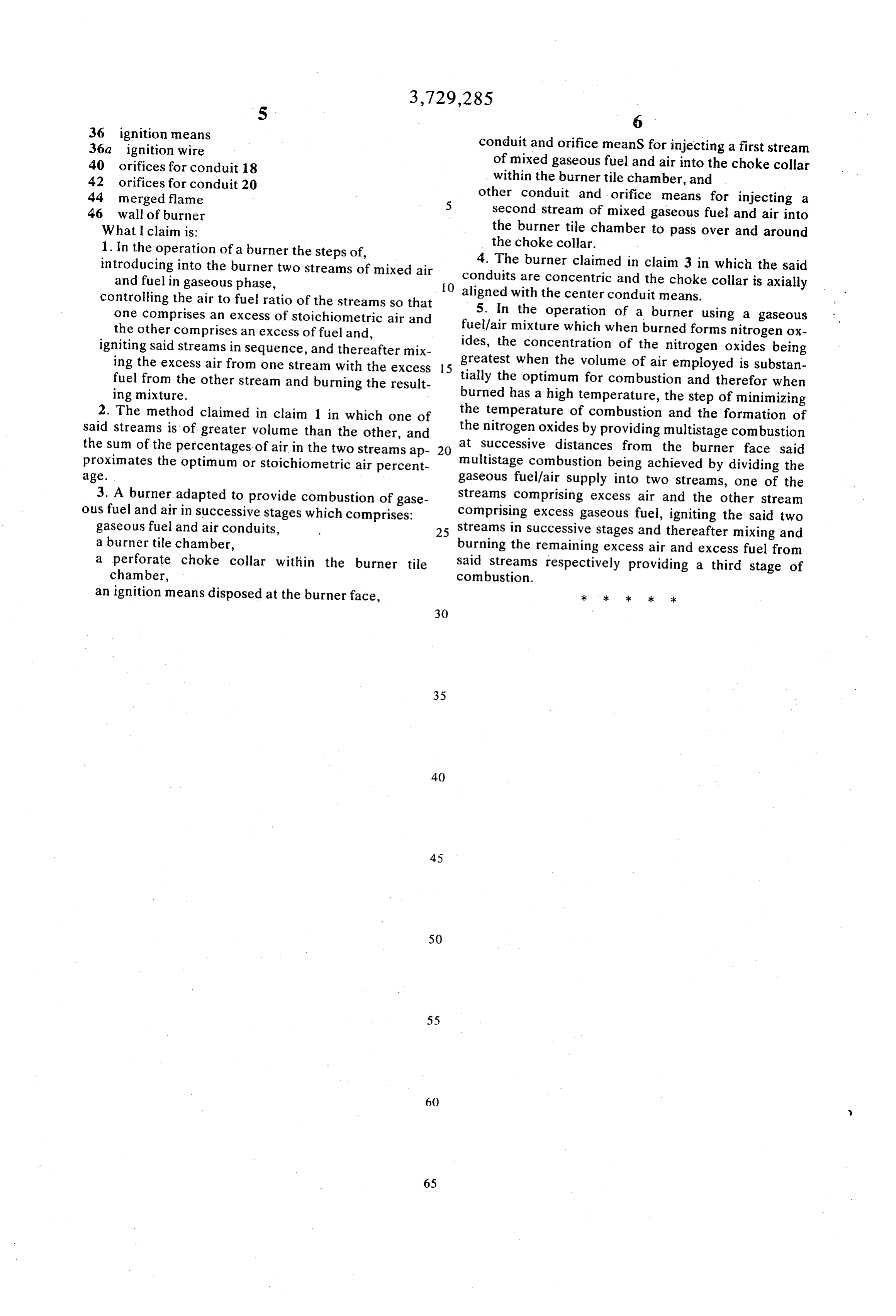
36 ignition means 36a ignition wire conduit and orifice meanS for injecting a first stream 40 orifices for conduit 8 of mixed gaseous fuel and air into the choke collar 42 orifices for conduit 20 within the burner tile chamber, and 44 merged flame other conduit and orifice means for injecting a 46 wall of burner second stream of mixed gaseous fuel and air into What I claim is: the burner tile chamber to pass over and around the choke collar.
1. In the operation of a burner the steps of, introducing into the burner two streams of mixed air 4. The burner claimed in claim 3 in which the said and fuel in gaseous phase, O conduits are concentric and the choke collar is axially controlling the air to fuel ratio of the streams so that aligned with the center conduit means. one comprises an excess of stoichiometric air and 5. In the operation of a burner using a gaseous the other comprises an excess of fuel and, fuel/air mixture which when burned forms nitrogen ox igniting said streams in sequence, and thereafter mix ides, the concentration of the nitrogen oxides being ing the excess air from one stream with the excess 15 greatest when the volume of air employed is substan fuel from the other stream and burning the result tially the optimum for combustion and therefor when ing mixture. burned has a high temperature, the step of minimizing 2. The method claimed in claim in which one of the temperature of combustion and the formation of said streams is of greater volume than the other, and the nitrogen oxides by providing multistage combustion the sum of the percentages of air in the two streams ap 20 at successive distances from the burner face said proximates the optimum or stoichiometric air percent multistage combustion being achieved by dividing the age. gaseous fuel/air supply into two streams, one of the 3. A burner adapted to provide combustion of gase streams comprising excess air and the other stream ous fuel and air in successive stages which comprises: comprising excess gaseous fuel, igniting the said two gaseous fuel and air conduits, 25 streams in successive stages and thereafter mixing and a burner tile chamber, burning the remaining excess air and excess fuel from a perforate choke collar within the burner tile said streams respectively providing a third stage of chamber, combustion.
an ignition means disposed at the burner face,
Provenance
- Collection
- Cited prior art
- Original PDF
- patentimages.storage.googleapis.com →
- Filed
- 1972-05-22
- Pages
- 5
- Method
- pdftotext (the PDF's own text layer) + pdftoppm 300dpi page scans
- Source
- Google Patents bibliographic record
- Granted
- 1973-04-24
- Inventors
- G Schwedersky
- Transcribed from
- patentimages.storage.googleapis.com →