patent · US3247024
Galvanic battery
19 April 1966
Page 1 — bibliographic record
April 19, 1966 P. J. TAMMINEN 3,247,024
GALWANIC BATTERY
Filed July 2, 1964 5 Sheets-Sheet 1
zza,
S 12 9 & 2 2% 2f SSSIKSSY 2 % S2 Se S2 2 N %. t 4 & 4 3, 2 7 y 7
estigiggitritish
As Wasternava. Sarasva
INVENTOR:
PENTT. J. TAMMINEN
Page 2
Drawing sheet — no readable text.
Page 3
Drawing sheet — no readable text.
Page 4
United States Patent Office 3,247,024 Patented Apr. 19, 1966
electrolyte temperature and composition in order to sus 3,247,024 tain a predetermined voltage level.
GALVANC BATTERY Another object of this invention is to provide an Pentti Juuse Tamminen, Otaniemi, Otakaliio S.A.7, electrochemical generator of the character described hav Helsiraki, Finland ing an improved electrode construction and configuration Filed July 2, 1964, Ser. No. 379,920 tending toward high output efficiencies.
6 Claims. (C. 136-140) Still a further object of this invention is to provide an improved method of operating liquid in electrolyte
My present invention relates to galvanic generators batteries and especially those galvanic generators in which of electric current and, more particularly, to galvanic O free electrolyte is in contact with the electrode surfaces. batteries of the type disclosed in my copending applica While it has been realized earlier, as mentioned above, tion Ser. No. 140,384, filed September 25, 1961, of which that the movement of electrolyte with respect to the the present application is a continuation-in-part. active electrode surfaces improves the efficiency of a In the aforementioned copending application, I de battery by carrying away depleted electrolyte and any scribe a liquid-electrolyte battery system in which the impurities which may have been found therein, there electrode efficiency can be markedly improved by the ex appears to have been little attention paid to the phe pedient of displacing one or more of the juxtaposed nomenon of ionic contamination or polarization at the electrodes relatively to the body of electrolyte in contact electrode-electrolyte interface. I have discovered that, therewith. As pointed out in this application, the im in spite of earlier indications that polarization layers proved electrode efficiency is believed to derive from the 20 could be eliminated merely through circulation of an mechanical elimination of polarizing ions in the region electrolyte with respect to the electrodes, mere move of the active electrode surfaces by the promotion of ment of the electrolyte along the active surfaces of the turbulence in the electrolyte in contact therewith. More electrode is insufficient to eliminate polarization layers specifically, it should be mentioned that it is a common proximal to the electrode surface and thus improve ionic difficulty, in batteries operating with both liquid and semi diffusion between the electrodes to any considerable ex liquid electrolyte, for one or both of the electrodes to tent. In most instances, the total elimination of po develop along its active surfaces a layer of ions which larization layers adjacent the electrode has been pre impede charging or discharging of the battery. It has, vented by disposing along one or both of the active therefore, been proposed heretofore to provide batteries, electrode surfaces porous or semipermeable membranes in which polarization is a problem, with means for effect 30 or separator sheets which, if anything, reduce the effec ing at least limited relative displacement of the electro tiveness of electrolyte movement. In other situations, lyte and the active surfaces in contact therewith. In the flow of electrolyte along the active surfaces effectively one conventional method, for example, gas bubbles are prevents entrainment of the polarizing contaminants by electrolytically generated in the electrode chamber or virtue of the boundary layers formed in the laminar stream a separator chamber communicating therewith to en of electrolyte. A laminar flow between battery elec train the electrolyte and thus displace it with respect to trodes is, as is evident from Reynolds-number considera the galvanic-current-generating electrodes. Under cer tions, difficult to prevent and, in fact, results even when tain circumstances, it has also been Suggested to em electrolyte is admitted between the electrodes through ploy pumps and the like to displace electrolyte, for ex 40 relatively narrow apertures. While the electrolyte stream ample through a plurality of apertures formed in the in the region of Such apertures may have some degree of electrodes of one or both polarities, and thus circulate turbulence, the major portion of the stream rapidly the electrolyte in contact with the electrode Surfaces. reverts to laminar flow with substantially stationary In still another arrangement, generally plate-like elec boundary layers of electrolyte liquid in contact with the trodes are employed, with the electrolyte being passed active electrode Surface. I have now discovered that to through the interelectrode gap parallel to the active elec 45 a large measure, the disadvantages of laminar flow under trode surfaces. In all of these prior-art systems, how the aforementioned conditions can be reduced, if not en ever, the most effective results were only to be obtained tirely eliminated, by interrupting the straight-line flow by pumping the electrolyte at such high rates as to render of electrolyte with one or more electrolyte-deflecting means the entire operation uneconomical. When reasonable elec overlying an active electrode surface and extending at trolyte speed and volume flow rates were employed, there 5 least partially transverse to the direction of flow of the was a noticeable failing off of the electrode efficiency. electrolyte from an inlet to an outlet of the electrode In addition, these earlier techniques could not give the chamber.
high electrode efficiency normally expected from de More specifically, it may be pointed out that the de polarizer-type batteries, for example. Even with earlier 55 flecting means, which, according to the present inven circulation methods, there was a noticeable decrease in tion, overlies at most a minor fraction of the active the terminal voltage of bateries especially when high surface so as not to impede ionic diffusion, promotes rate discharges were carried out as Well as a measur the entrainment of polarizing contaminants along this able decline in the total discharge capacity of the sys surface and insures substantially complete elimination of tem. the waste products. The battery should, therefore, in It is the principal object of the present invention to O clude at least one electrode chamber having an electro provide a galvanic electrical generator of the character lyte inlet and an electrolyte outlet at generally longi described which is capable of delivering large currents tudinally opposite sides of the active electrode surface, without appreciable voltage declines for prolonged periods means being provided to effect relative displacement of as compared with earlier galvanic batteries. the electrolyte and the surface in contact therewith. While A corollary object of this invention resides in the it is preferred to forcibly drive the electrolyte through provision of a galvanic battery having improved electrode the electrode chamber and past the electrodes, thereby efficiency and characterized by a substantial reduction in increasing the effectiveness of the turbulence-generating residual polarization at the electrode-electrolyte inter eflecting means mentioned above, it should be noted faces. O that the relative displacement can also be produced by reciprocating one or more of the electrodes in the elec
Still another object of this invention is to provide a battery having means for compensating variations in trode chamber by gross movement of the battery hous
Page 5
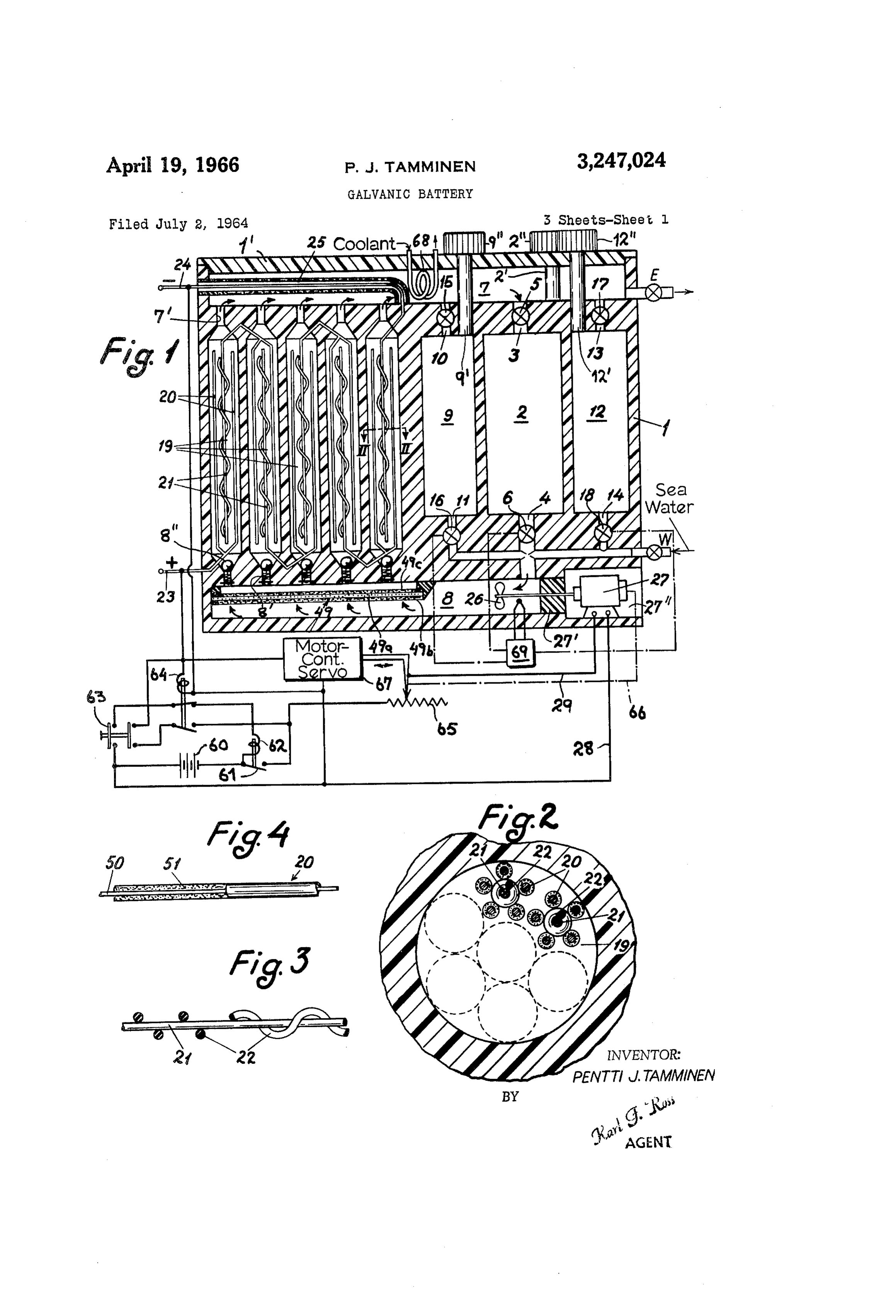
ing or casing or individual or joint movement of the FIG. 2 is a cross-sectional view taken along the line electrodes with respect to the battery housing. In each II-II of FIG. 1;
case, however, the deflecting means acts in such manner FIG. 3 is an elevational view of a central electrode as to prevent flow of the electrolyte in a straight line of the type employed in the battery of FIG. 1 showing across the electrode and induce a turbulence sufficient to 5 the helically wound separator, partly broken away; improve the efficiency of the battery to an extent such FIG. 4 is a partial cross-sectional view of a counter that the means for generating the turbulence can be electrode;
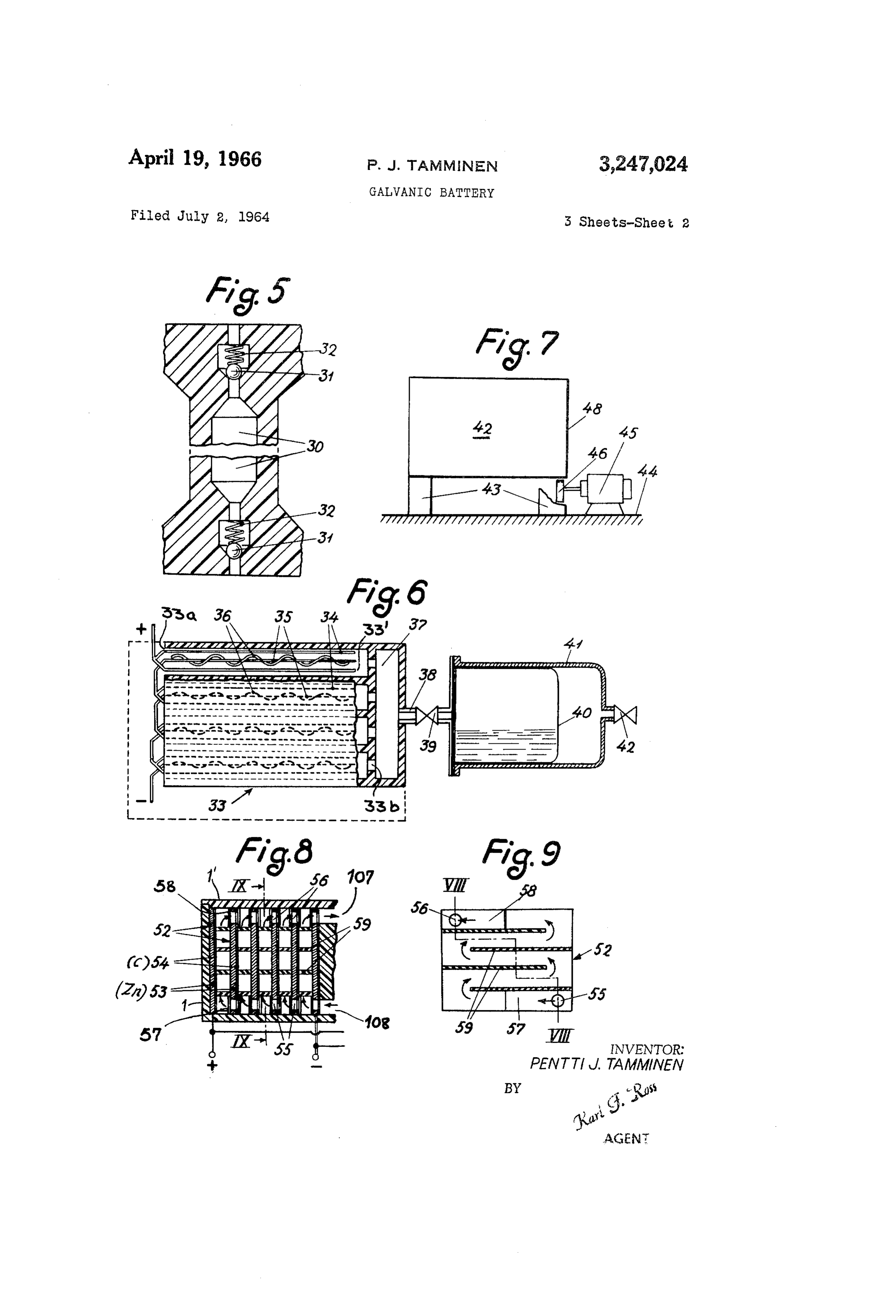
powered by the battery itself without any power loss. FIG. 5 is an axial cross-sectional view through an The movement-producing means can, therefore, be elec electrode compartment of a modified battery, according tromagnetically operable and connected to the output ter O to this invention, with the electrodes removed; minals of the battery for energization thereby. FIG. 6 is a cross-sectional view through another battery According to a more specific feature of the present with a two-part housing;
invention, the galvanic generator is formed with hous FIG. 7 is a diagrammatic elevational view, partly broken ing means which may be integral or constituted by two away, showing means for vibrating the battery casing separated sections forming at least one electrode cham and suitable for use in conjunction with the embodi ber and an electrolyte reservoir along with a substan ment of FIG. 1;
tially closed electrolyte-circulation path from the reser FIG. 8 is a fragmentary cross-sectional view of the voir and through the chamber. Along this path, there electrode compartment of still another battery taken along can be disposed displacement-pump means for circulating the line VIII-VIII of FIG. 9, this compartment being a stream of electrolyte through the chamber whose elec 20 adapted to be substituted for the electrode compartments trodes may consist of wires generally parallel to the of the battery of FIG. 1;
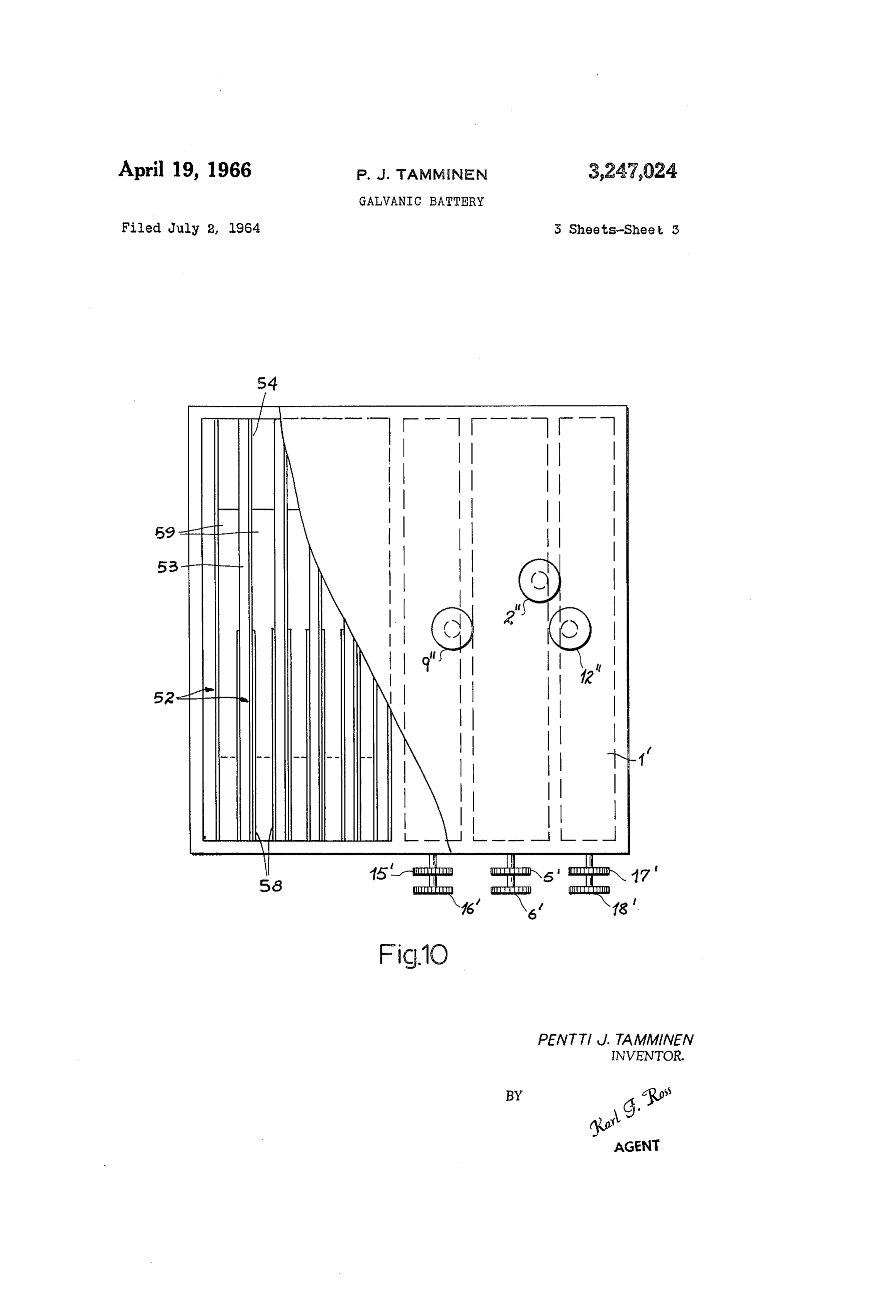
direction of electrolyte flow. In this case a central elec FIG. 9 is a cross-sectional view taken along the line trode of one polarity can be surrounded by a plurality IX-IX of FIG. 8; and of parallel-connected electrodes of opposite polarity, with FIG. 10 is a top view of the battery of FIG. 8, show the deflecting means constituted by a relatively thin ing valve-control means also seen in FIG. 1; and hav helical member wound around the central electrode and ing part of the housing broken away to expose the plate serving as the sole separator means along the juxtaposed structure of FIGS. 8 and 9.
length of the electrodes for maintaining the spacing there In FIG. 1, I show a sectional view of a battery whose between. The helically wound separator can thus be casing 1 made of a suitable insulating material such as coaxial with the central electrode and, according to an 30 polyvinyl resin, an ABS resin, or a hard rubber has formed important feature of the present invention, should have within it a plurality of electrode-containing cell chambers a pitch substantially in excess of the width of the non 19, these chambers having a cylindrical configuration with conductive separator member in the longitudinal direc upright longitudinal axes. The electrode chambers con tion so that the separator itself does constitute a barrier municate via narrow outlet and inlet passages 7, 8 with of any significant extent to the direct ionic path between channels 7 and 8, respectively. Valves 8' prevent entry electrodes. Alternatively, the electrodes can be constituted of electrolyte into the chambers in the absence of a pre as stacked parallel plates with the deflecting means determined electrolyte pressure. formed as thin bars separating the plates from one an The channels 7, 8 serve to join the electrode chambers other and forming an undulating path for the electrolyte 9 to acid- and electrolyte-containing chambers 9, 2 and along the electrode surfaces. 40 12 via a series of ports and valves. The chamber 2 con
This undulating path is, of course, similar in function tains an electrolyte mixture of chromic acid, sulphuric acid. to the vortex movement of the electrolyte created by and water, and is connected at one end to outlet channel the helical separator mentioned above. The bars should, 7 by means of a port 3 and a valve 5, whose operating of course, be spaced apart in the longitudinal direction member is shown at 5' in FIG. 10, and at the other end to and staggered to form the undulating path. inlet channel 8 by means of a port 4 and a valve 6, the lat Batteries of the character described above have been ter being controlled by a handle 6. Chamber 9, which found to be highly advantageous even when the electric contains chronic acid, and chamber 12, which contains current employed for the pump or vibrating means is Sulphuric acid, are connected to channel 7 by port E.0, extracted from the battery. In this connection, it may valve 5, and port 13, valve 7, respectively; they are also be noted that the pump motor can be energized by an connected to channel 8 by means of port 11, valve 16 and external source until the battery voltage is sufficient to port 14, valve 3 respectively, the ports 11 and 4 conn energize the motor, whereupon the external source can municating with port 4 forwardly of valve 6. Valves be automatically cut off by suitable voltage-responsive 15-17 are controlled by adjusting members 14 to 17 re means and the motor connected across the battery ter spectively.
minals. 55 In applications where water is readily available, as in Under circumstances in which a propeller pump driven connection with underwater devices, it is preferred to pro by an electromotor is used, the increase in the weight vide both the aqueous chromic-acid solution of reservoir of the battery is about 5% while the delivered energy 9 and the sulphuric acid of reservoir 2 in highly concen during high-rate discharge can be as much as 100% in trated form, the sulphuric acid possibly even in the form excess of that absent the pump. The power consumption 60 of oleum (H2SO4 with dissolved SO). These solutions of the motor is only about 0.3%, a negligible amount must be diluted before addition to the electrolyte. For compared with the resulting gain. The circulation of this purpose the battery of FIG. 1 is provided with water electrolyte, moreover, increases the use of the depolariz pipe W through which the proper amount of water can ing substance and reduces the internal resistance of the be gradually fed to the battery. At the same time a battery, thereby diminishing the inherent voltage drop 65 minor part of the partly exhausted electrolyte, correspond during discharge. The circulation of electrolyte, more ing to the volume of additional water, is discarded through over, substantially increases the concentration of electro exhaust pipe E, which is preferably installed at the end lyte which can be used, thereby further increasing the of channel 7. This arrangement considerably improves capacity of the generator. the capacity of the battery, by increasing the amount of The above and other objects, features and advantages 70 active electrolyte ingredients and by eliminating zinc ions of the present invention will become more readily ap and so improving the solubility of zinc electrodes. parent from the following description, reference being For the sake of clarity, the electrode chambers 9 as made to the accompanying drawing, in which: shown in FIG. 1 contain only two positive electrodes 20 FIG. 1 is a vertical cross-sectional view through a and one negative electrode 21, said negative electrode galvanic generator embodying the present invention; being provided with a helically wound dielectric separator
Page 6
22 (e.g. a polystyrene filament), as shown in FIG. 3. The Another method of re-activating the electrolyte is to positive electrodes 20 each have a conducting core 50 of provide reservoirs, such as those shown in FIG. 1 at 9 and copper wire coated with a plastic material 51, which has 12, filled respectively with concentrated chromic acid and been made conductive by impregnating it with small parti concentrated sulfuric acid, which can be added to the cles of carbonaceous material, such as graphite and acet 5 electrolyte flow as needed by opening valves 15 and 16 ylene black, as shown in FIG. 4. The negative electrode of chamber 9 and valves 17 and 18 of chamber 12. By is a zinc wire. The positive electrodes of each cell, which proper dimensioning of the ports 10, 11 of chamber 9 are angularly spaced about the negative electrode, are in and 13, 14 of chamber 2 and/or the valves 15, 16 of terconnected in parallel and jointly connected in Series chamber 9 and valves 17, 8 of chamber 12, it is possible with the negative electrode of an adjoining cell preferably O to obtain an addition of sulfuric acid and chromic acid in the same compartment. in substantially the same proportion as they are con As shown in FIG. 2, however, a plurality of electrode sumed in the reaction. If, additionally, the increase of clusters constitute the cells and are contained within each zinc-ion concentration is held in check as indicated, by of the electrode compartments 19, each cluster being pro discarding partly exhausted electrolyte with simultaneous vided with a plurality of positive electrodes 20 grouped addition of water, the voltage of the battery will be kept about one negative electrode 21, the positive and negative stable over fairly extending periods. electrodes 20, 21 being spaced from one another Solely Still another effective way of compensating for the loss by the helical separator 22. The latter covers only a of electrolyte activity as the battery is discharged is small fraction of the active electrode surface and generates gradually to increase the speed of electrolyte flow, by pro a helical vortex upon circulation of electrolyte. Since the 20 viding the motor 27 with a potentiometer 65 which can chambers 9 are almost completely filled with electrode be geared to the motor drive shaft as diagrammatically ill clusters, only narrow passages are left for the electrolyte lustrated by dot-dash line 66 to increase the voltage to the to flow through, and as the ratio of positive electrode Sur motor at the same rate as the electrolyte is exhausted. face area to negative electrode surface area is considerably Alternatively, or concurrently, the decrease in output larger than that of earlier batteries, the internal resistance voltage due to depletion of the electrolyte can be sensed of the battery is substantially reduced. by a servo 67, which drives the potentiometer to maintain The oppositely poled electrodes of the battery cells are the output voltage.
connected in series as previously indicated, the positive It has been discovered that an elevated electrolyte tem potential being brought out of the casing by a terminal perature between 50° C. and 80° C. is favorable for the 23 and the negative potential being brought out by a 30 best efficiency of a chromic-acid battery. Since the heat terminal 24; part of the lead for the latter terminal, ex generated during the heavy discharge of these batteries tending from the center of the battery by way of channel may be quite strong, it may be advantageous to provide 7, is covered with a tube of insulating material 25. cooling means, such as a coil 68, in the circulation system The circulation of the electrolyte through the battery in order to keep the temperature within the desired limits. chambers 19 is provided by a propeller pump 25 located If, on the other hand, the battery is intended for use in channel 8 and driven by an electric motor 27, isolated under low temperature conditions, it will be desirable to from the circulating electrolyte by a seal 27, and mounted provide for heating of the electrolyte in order quickly in a recess 27' of the battery casing . The notor 27 is to obtain the full efficiency of the battery. Such heating electrically connected to the battery terminals 23, 24 by 40 may be effected in a convenient manner by mixing the conductors 28 and 29, via a control circuit. Feed tubes concentrated sulfuric acid and a diluted solution of 2', 9' and 12, provided with respective closures 2', 9' chromic acid from reservoirs 9 and 12 in accordance with and 12' in the cover' of the casing, serve to permit fill the temperature as measured by a thermosensitive device ing of the electrolyte reservoirs 2, 9 and 12, respectively. 69 which can regulate valves 16 and 18. The mixing To put the battery into operation, an external source of together of these acids will cause a rapid rise in the tem current 60 is applied to the motor 27, via relay contacts perature of the resultant electrolyte to a value within the 65, upon energization of relay 62 by an on-off switch 63, above-mentioned limits.
while the valves 5 and 6 are opened, releasing the elec When applying the invention to storage batteries and trolyte from chamber 2 into channel 8, this channel being primary batteries intended for intermittent use, it is pref either empty or filled with inert distilled water prior to erable to close the open ends of the electrode-containing activation of the battery. As the electrolyte fills channel cells in order to prevent leakage currents during inactive 8, it is driven by propeller pump 26 through a filter 49 periods. The best way to do this is to provide the cells provided for the removal of any solid particles of foreign with valves at both their open ends. Such an arrange matter which may be present in the electrolyte. The elec ment is illustrated in FIG. 5. An electrode-containing trolyte then enters the chambers 19 by displacement of the cell 30, similar to those shown in FIG. 1, is shown with valves 8', where it is forced through the narrow openings 5 5 its top and bottom passageways blocked by spring-loaded between the electrode clusters, the helical separators 22 balls 31, acting as one-way valves. The springs 32 have creating strong turbulence of the electrolyte through the a force-constant adapted to open the valves at a prede electrodes, thereby causing a thorough diffusion of active termined pressure of the electrolyte, caused by the pump, ions between electrodes. The electrolyte then leaves the and to close them automatically when that pressure drops. chambers 19, taking with it the reaction products, and re 60 One material advantage of applying electrolyte flow enters the cycle via channel 7. in accordance with the invention in storage batteries is As soon as the battery starts to generate a voltage, a that it will be possible to charge these batteries with very voltage-responsive relay 64 is energized to inactivate ex high currents.
ternal current source 60 driving the motor 27 and con Batteries intended for very short discharge periods nects the battery voltage of terminals 23, 24 across said (high-rate discharges) may be designed in such a man
During discharge the electrolyte will slowly lose its ner as to discard the electrolyte after it has flowed once activity. In order to keep the voltage stable, means may through the cells, without recirculating it. FIG. 6 illus be provided for compensating lost activity of the elec trates such an embodiment of the present invention. The trolyte. elongated chambers 33' of battery 33 have a relatively O Simall cross-sectional area, containing clustered electrodes
One method of re-activating the electrolyte is to in 34 and 35, the electrodes 35 each carrying a helically corporate in the filter 49 crystalline CrO3, which activates Wound separator 36 and being similar to the electrodes the exhausted electrolyte as it is re-cycled. These ac and separator shown in the embodiment of FIG. 1. tivators 49a are disposed between fiber-glass layers 49b The chambers 33' have one of their ends 33a open as an and 49c. 5 outlet to allow the electrolyte to be discarded after use,
Page 7
while the other ends 33b are inlets opening into a dis example of a battery having a diaphragm. In a Bunsen tributing channel 37. An electrolyte container 40, which battery constructed in accordance with the invention, one is made of a collapsible material and protectively con circulation system would include sulfuric acid and zinc tained within a jacket 41, is connected to the distributing electrodes, and the other would include nitric acid and channel 37 through a conduit 38 and a pressure-respon 5 carbon electrodes. Both the positive and negative elec sive valve 39. The rigid jacket 41 also contains a pres trodes may in that case be provided with helically wound sure medium, such as a gas, and is provided with a valve separators to cause a turbulent flow of electrolyte. 42 for introducing said medium into the jacket. Depending upon the type of battery, it is, according to When activating the battery shown in FIG. 6, the valve the invention, also possible to use an electrolyte comprising 39 is opened and the pressure medium compresses the col finely divided particles of a depolarizing material, such as lapsible container 40, forcing the electrolyte through con manganese-dioxide crystals, and a conductive material, duit 38 into distributing channel 37 and then through the such as graphite, in order to enlarge the active depolariz chambers 33' where a vortex-type turbulence is produced ing surface. In this case no filter is used, and the pump in the electrolyte by the helical separators 36, the electro gmust be selected to meet the requirements of the high lyte being then expelled through the open ends of the 15 density mixture.
cells. I claim:
In a battery of this type it is advantageous to use a 1. A galvanic battery comprising: highly active electrolyte whereby the speed of flow of the housing means forming at least one electrode chamber electrolyte may be reduced by adjusting the valve 39, and at lease one electrolyte reservoir communicating thereby prolonging the discharge period. therewith;
It has been discovered that vibration has a favorable a set of substantially parallel electrode plates spacedly effect on the efficiency of the battery. This fact is be disposed in said chamber between opposite chamber lieved to be due to the phenomenon that vibration causes walls for defining electrolyte compartments between turbulence adjacent the surface of the electrodes when the them, said plates having confronting active surfaces deflecting means previously described is employed. To of opposite polarity as boundaries for said compart make use of this phenomenon, the motor 27 of the em ments;
bodiment shown in FIG. 1 may be provided with a slight means in said housing means forming a substantially ly eccentric cam plate so as to cause vibration when run closed electrolyte-circulation path from said reservoir ning. In some cases, especially in batteries intended for to said chamber and thence back to said reservoir by very short discharge periods, it is possible to use only 30 way of said compartments; vibrations and omit the circulation system entirely, since liquid displacement pump means along said path for the turbulence caused by the vibration alone will increase circulating a stream of electrolyte through said com the activity of the battery to a sufficient degree. FIG. 7 partments;
schematically illustrates such an arrangement. A battery and a set of relatively staggered insulating baffles ex generally indicated at 42 and of the type illustrated in 35 tending substantially parallel and transversely within FIG. 1, is supported by pads 43 of an elastomeric ma each compartment between the electrode plates there terial, such as rubber, these pads being secured to the bat of and holding same spaced apart, alternate baffles tery and to a suitable base member 44. The base mem extending overlappingly from opposite chamber walls ber 44 further carries an electric motor 45 whose shaft within the compartment for defining a meandering is provided with a cam plate 46 engaging the casing 48 40 passage for said electrolyte. of battery 42. When the motor 45 rotates, the cam 2. A battery as defined in claim 1 wherein each plate plate 46 will cause the whole battery to vibrate. To in interposed between a pair of adjoining compartments is a crease the relative movement of the electrode and the bipolar electrode with surfaces formed from conductive electrolyte, the central electrode of each cluster, carry materials of different polarities respectively facing said ad ing the helical separator, can be resiliently mounted (e.g. joining compartments.
by springs) and provided with a weight increasing the os 3. A battery as defined in claim 2 wherein said electro cillation period of the electrode. lyte is an aqueous solution of chromic acid and sulfuric The embodiment shown in FIGS. 8, 9, and 10 is in acid, said bipolar electrodes each comprising a zinc sheet tended for applications where a higher voltage is required. and a carbon layer disposed upon one surface of Said A plurality of parallel, spaced bipolar electrode plates 52 sheet.
are formed by zinc plates 53 coated on one side with an 4. A battery as defined in claim 3 wherein said carbon inert conductive carbonaceous layer 54, advantageously layer is provided with a multiplicity of turbulence-pro having a rough corrugated or grooved surface. A plu Tmoting formations.
rality of parallel spaced insulating baffle bars 59, in a plane 5. A battery as defined in claim 1 wherein said plates perpendicular to that of the electrode plates 52 and of a 55 are substantially vertical and provided with a set of first length somewhat less than that of the electrode plates 52, perforations at a level below said baffles and with a set of serve as separators for these electrodes and also provide second perforations at a level above said baffles, said path a meandering path for the flow of electrolyte through the including an inlet channel communicating with one of said channels formed by the interrelationship of these baffle sets of perforations and an outlet channel communicating bars 59 and electrode plates 52. The electrode plates 53 60 with the other of said sets of perforations. are provided with openings 55, 56 along longitudinal op 6. A battery as defined in claim 5 wherein said plates posite sides for the flow of electrolyte between plates, the are rectangular and said openings are disposed at di area adjacent to the openings being covered on both sides agonally opposite corners of said plates. by insulating layers 47, 58 (FIG. 9) to prevent short cir References Cited by the Examiner cuits. The flow of electrolyte can be generated by means 65 UNITED STATES PATENTS already described in FIG. 1 (with inlet and outlet channels 108, 107 corresponding to channels 8 and 7 thereof), the 734,549 7/1903 Halsey ------------- 136-160 flow becoming turbulent as it is forced around the baffles 2,921,111 1/1960 Crowley et al. ------- 136-160 59 and past the rough Surface of coating 54, this surface 2,936,327 5/1960 Schrodt et al. -------- 136-162 also contributing to the turbulence. FOREIGN PATENTS The invention may of course also be applied to battery 15,257 1893 Great Britain. types using an electrolyte other than chromic acid. It 18,886 1906 Great Britain. may be necessary in some cases to divide the cells by a diaphragm and arrange two parallel, separate circulation WINSTON A. DOUGLAS, Primary Examiner.
Systems. A so-called Bunsen battery is mentioned as an 15 JOHN H. MACK, Examiner.
Provenance
- Collection
- Cited prior art
- Original PDF
- patentimages.storage.googleapis.com →
- Filed
- 1964-07-02
- Pages
- 7
- Method
- pdftotext (the PDF's own text layer) + pdftoppm 300dpi page scans
- Source
- Google Patents bibliographic record
- Granted
- 1966-04-19
- Inventors
- Tamminen Pentti Juuse
- Transcribed from
- patentimages.storage.googleapis.com →