patent · US3192133
Devices for solar distillation
29 June 1965
Page 1
Drawing sheet — no readable text.
Page 2
Drawing sheet — no readable text.
Page 3
Drawing sheet — no readable text.
Page 4
Drawing sheet — no readable text.
Page 5
United States Patent Office Patented June 29, 1965
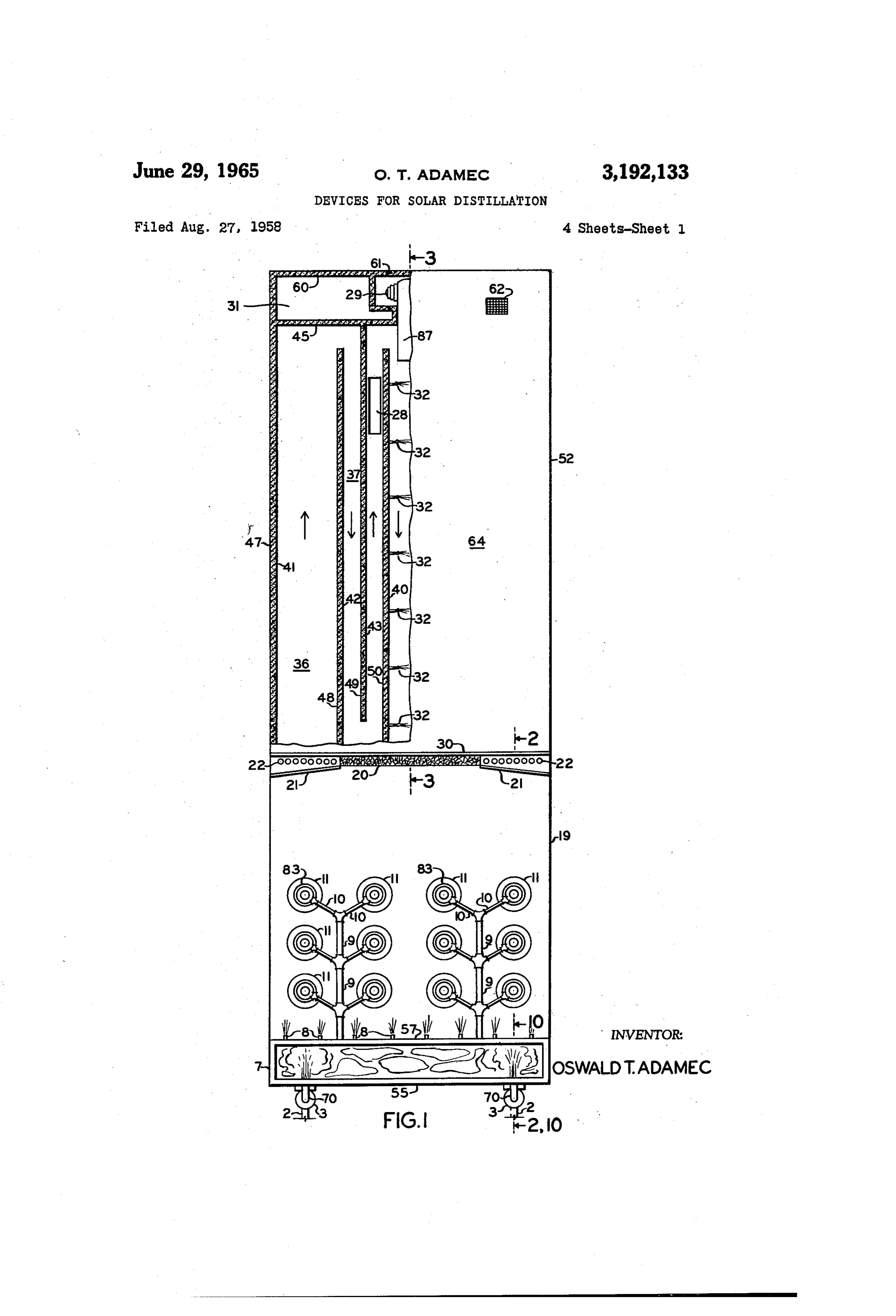
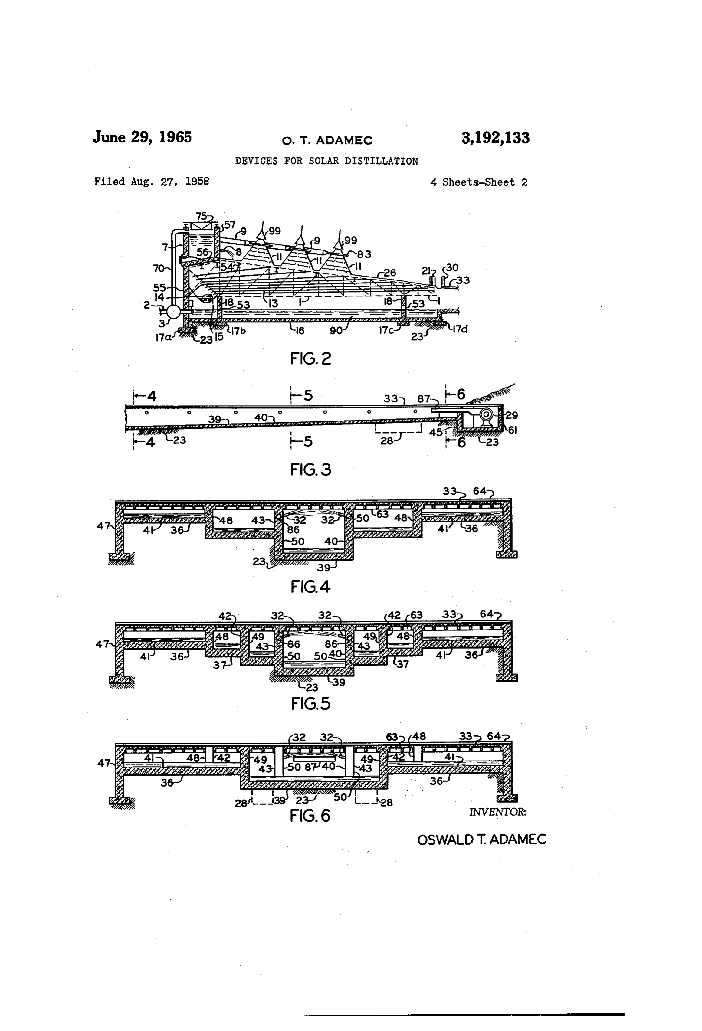
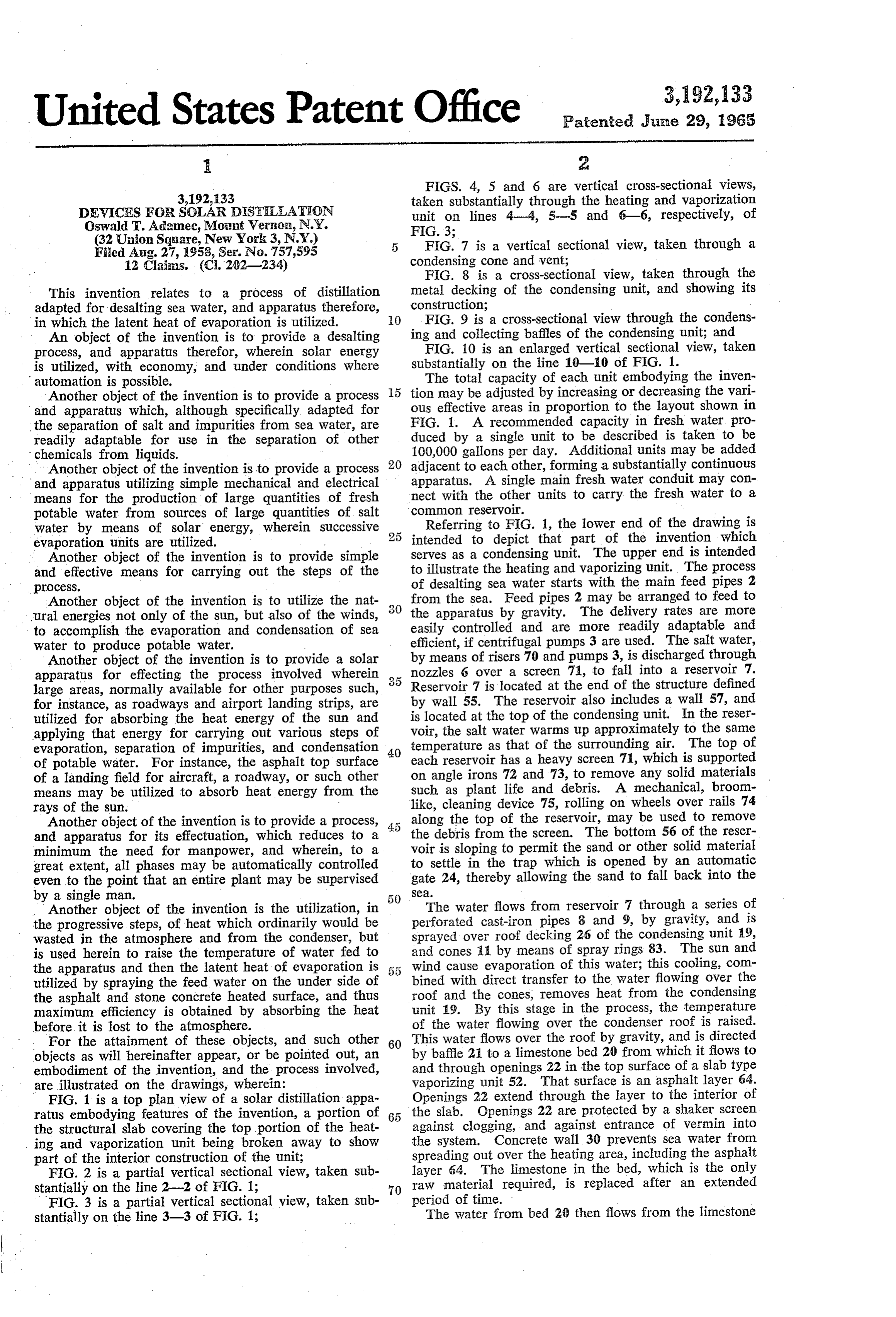
FIGS. 4, 5 and 6 are vertical cross-sectional views, 3,192,133 taken substantially through the heating and vaporization
DEVICES FOR SOLAR DISTILLATION unit on lines 4-4, 5-5 and 6-6, respectively, of Oswald T. Adamec, Mount Vernon, N.Y. FIG. 3;
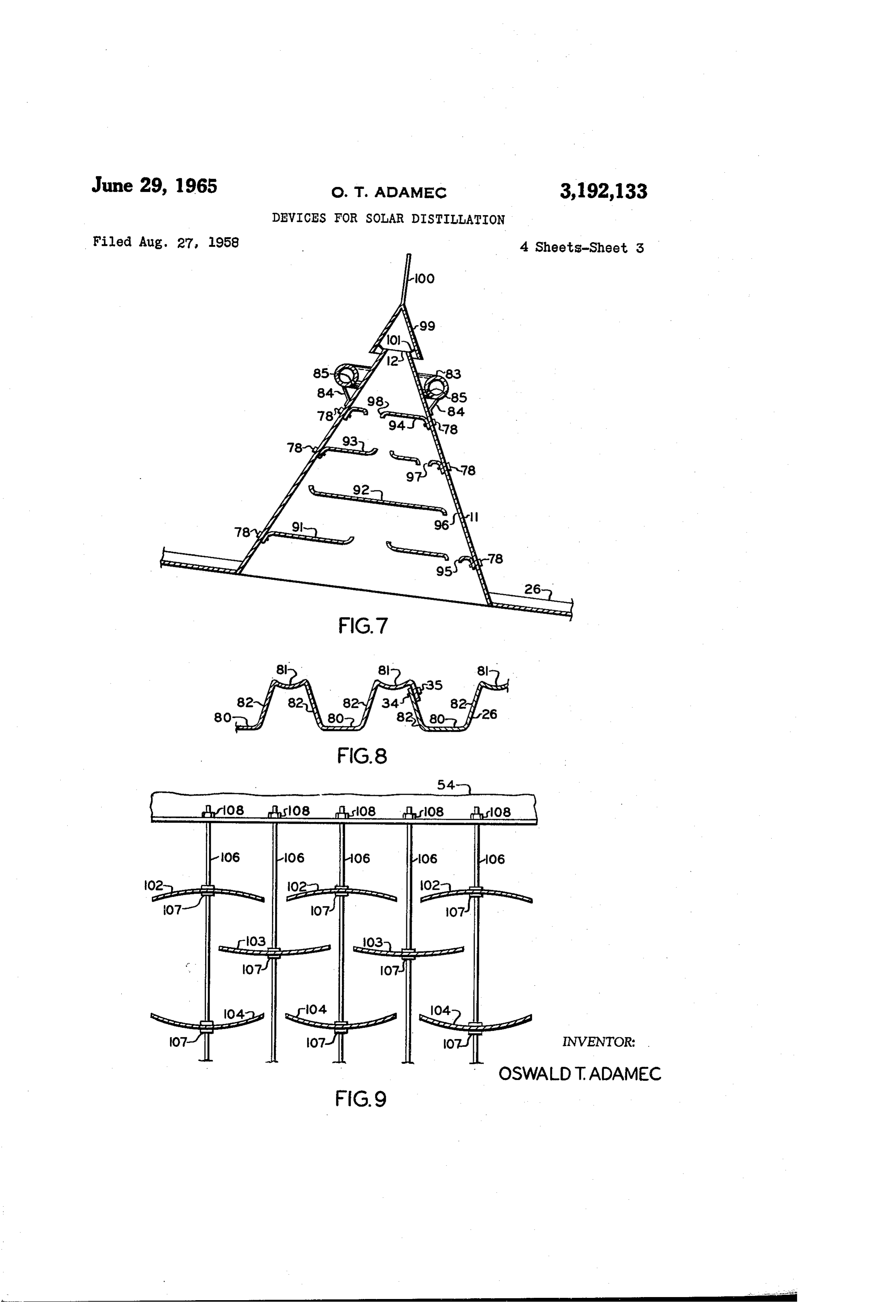
(32 Union Square, New York 3, N.Y.) 5 FIG. 7 is a vertical sectional view, taken through a Filed Aug. 27, 1958, Ser. No. 757,595 condensing cone and vent;
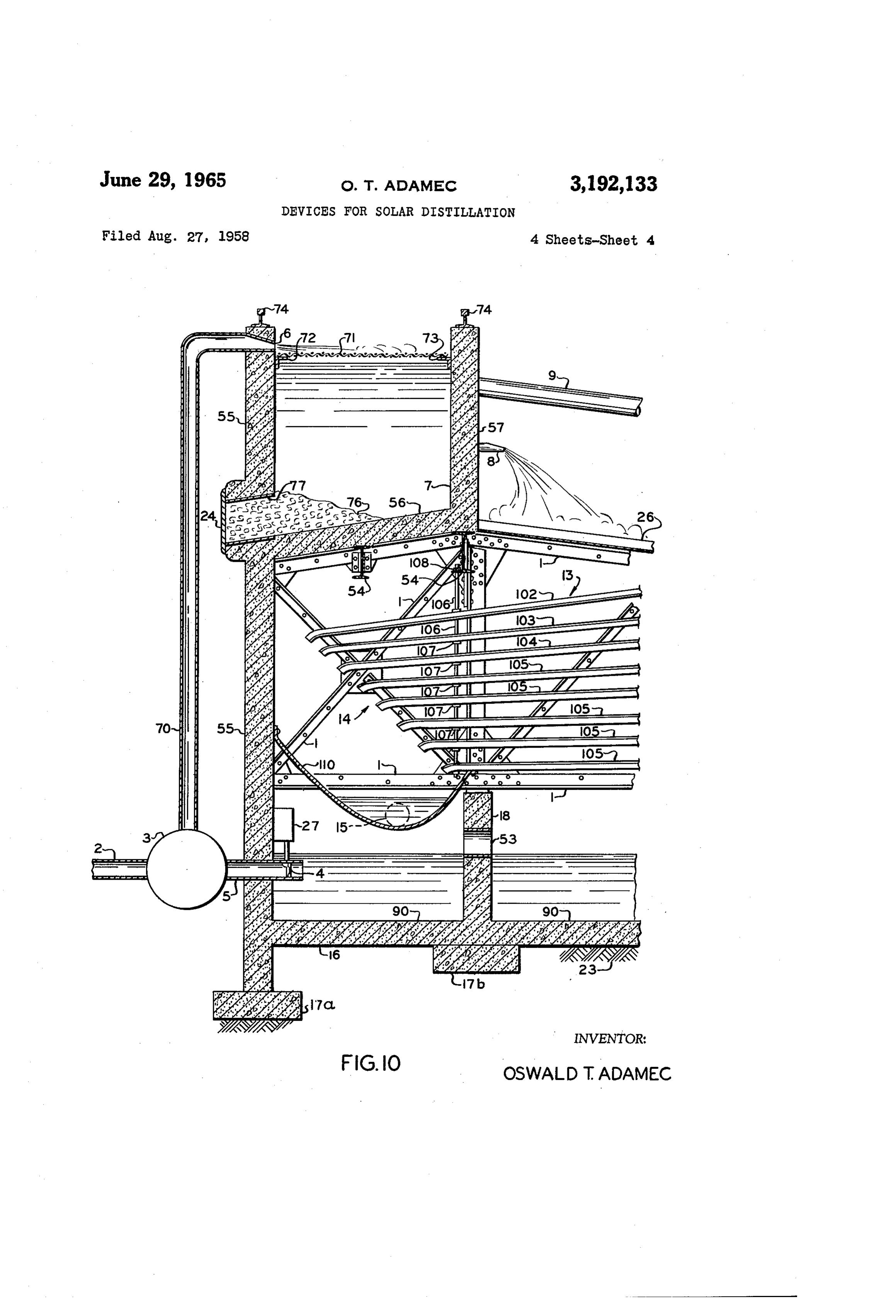
12 Clainas. (C. 202-234) FIG. 8 is a cross-sectional view, taken through the This invention relates to a process of distillation metal decking of the condensing unit, and showing its adapted for desalting sea water, and apparatus therefore, construction;
in which the latent heat of evaporation is utilized. 0 FIG. 9 is a cross-sectional view through the condens An object of the invention is to provide a desalting ing and collecting baffles of the condensing unit; and process, and apparatus therefor, wherein solar energy FIG. 10 is an enlarged vertical sectional view, taken is utilized, with economy, and under conditions where substantially on the line 10-0 of FIG. 1. The total capacity of each unit embodying the inven automation is possible.
Another object of the invention is to provide a process tion may be adjusted by increasing or decreasing the vari and apparatus which, although specifically adapted for ous effective areas in proportion to the layout shown in the separation of salt and impurities from sea water, are FIG. 1. A recommended capacity in fresh water pro readily adaptable for use in the separation of other duced by a single unit to be described is taken to be chemicals from liquids. 100,000 gallons per day. Additional units may be added Another object of the invention is to provide a process 20 adjacent to each other, forming a substantially continuous apparatus. A single main fresh water conduit may con and apparatus utilizing simple mechanical and electrical means for the production of large quantities of fresh nect with the other units to carry the fresh water to a potable water from sources of large quantities of salt common reservoir.
Water by means of solar energy, wherein successive 25 intended to todepict
Referring FIG. 1, the lower end of the drawing is that part of the invention which evaporation units are utilized.
Another object of the invention is to provide simple to serves as a condensing unit. The upper end is intended and effective means for carrying out the steps of the of illustrate the heating and vaporizing unit. The process desalting sea water starts with the main feed pipes 2 process.
Another object of the invention is to utilize the nat from the sea. Feed pipes 2 may be arranged to feed to ural energies not only of the sun, but also of the winds, the apparatus by gravity. The delivery rates are more to accomplish the evaporation and condensation of sea easily controlled and are more readily adaptable and water to produce potable water. efficient, if centrifugal pumps 3 are used. The salt water, Another object of the invention is to provide a solar by means of risers 70 and pumps 3, is discharged through apparatus for effecting the process involved wherein nozzles 6 over a screen 71, to fall into a reservoir 7. large areas, normally available for other purposes such, Reservoir 7 is located at the end of the structure defined for instance, as roadways and airport landing strips, are by wall 55. The reservoir also includes a wall 57, and utilized for absorbing the heat energy of the sun and is located at the top of the condensing unit. In the reser applying that energy for carrying out various steps of voir, the salt water warms up approximately to the same evaporation, separation of impurities, and condensation 40 temperature as that of the surrounding air. The top of of potable water. For instance, the asphalt top surface each reservoir has a heavy screen 7, which is supported of a landing field for aircraft, a roadway, or such other on angle irons 72 and 73, to remove any solid materials means may be utilized to absorb heat energy from the such as plant life and debris. A mechanical, broom rays of the sun. - like, cleaning device 75, rolling on wheels over rails 74 Another object of the invention is to provide a process, along the top of the reservoir, may be used to remove and apparatus for its effectuation, which reduces to a the debris from the screen. The bottom 56 of the reser minimum the need for manpower, and wherein, to a voir is sloping to permit the sand or other solid material great extent, all phases may be automatically controlled to settle in the trap which is opened by an automatic even to the point that an entire plant may be supervised gate 24, thereby allowing the sand to fall back into the by a single man. Sea.
. . Another object of the invention is the utilization, in The water flows from reservoir 7 through a series of the progressive steps, of heat which ordinarily would be perforated cast-iron pipes 8 and 9, by gravity, and is wasted in the atmosphere and from the condenser, but sprayed over roof decking 26 of the condensing unit 19, is used herein to raise the temperature of water fed to and cones is by means of spray rings 83. The Sun and the apparatus and then the latent heat of evaporation is 5 5 wind cause evaporation of this water; this cooling, com utilized by spraying the feed water on the under side of bined with direct transfer to the water flowing over the the asphalt and stone concrete heated surface, and thus roof and the cones, removes heat from the condensing maximum efficiency is obtained by absorbing the heat unit 19. By this stage in the process, the temperature before it is lost to the atmosphere. of the water flowing over the condenser roof is raised. For the attainment of these objects, and such other 60 This water flows over the roof by gravity, and is directed objects as will hereinafter appear, or be pointed out, an by baffle 21 to a limestone bed 20 from which it flows to embodiment of the invention, and the process involved, and through openings 22 in the top surface of a slab type are illustrated on the drawings, wherein: vaporizing unit 52. That surface is an asphalt layer 64. FIG. 1 is a top plan view of a solar distillation appa Openings 22 extend through the layer to the interior of ratus embodying features of the invention, a portion of 65 the slab. Openings 22 are protected by a shaker screen the structural slab covering the top portion of the heat against clogging, and against entrance of vermin into ing and vaporization unit being broken away to show the system. Concrete wall 30 prevents sea water from part of the interior construction of the unit; spreading out over the heating area, including the asphalt FIG. 2 is a partial vertical sectional view, taken sub layer 64. The limestone in the bed, which is the only stantially on the line 2-2 of FIG. 1; 70 raw material required, is replaced after an extended FIG. 3 is a partial vertical sectional view, taken sub period of time.
stantially on the line 3-3 of FIG. 1; The water from bed 26 then flows from the limestone
Page 6
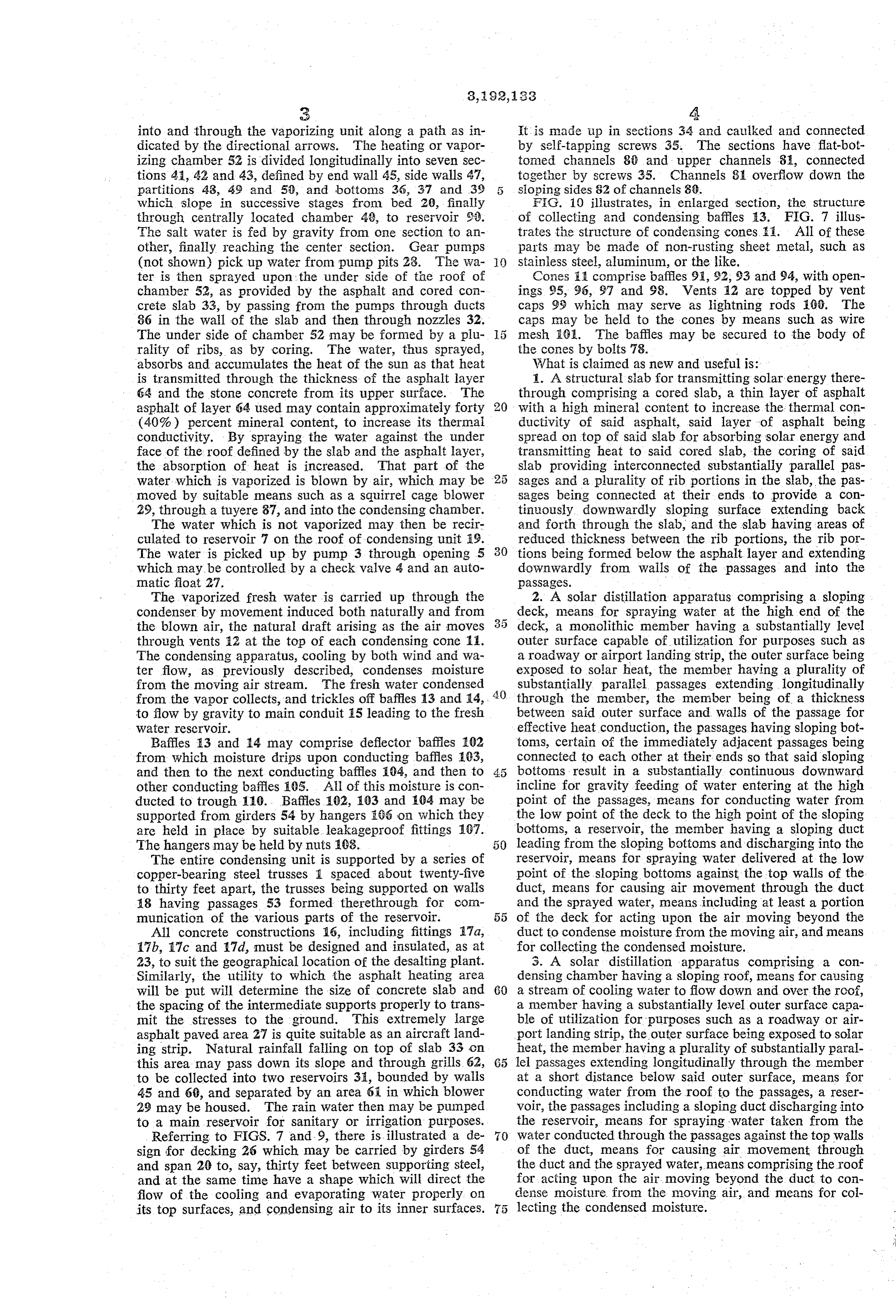
into and through the vaporizing unit along a path as in It is made up in sections 34 and cauiked and connected dicated by the directional arrows. The heating or vapor by self-tapping screws. 35. The sections have flat-bot izing chamber 52 is divided longitudinally into seven Sec tomed channels 88 and upper channels 81, connected tions 41, 42 and 43, defined by end wall 45, side walls 47, together by screws 35. Channels 81 overflow down the partitions 43, 49 and 5), and bottons 36, 37 and 39 5 sloping sides S2 of channels 89.
which slope in successive stages from bed 20, finally Fig. 10 illustrates, in enlarged section, the structure through centrally located chamber 4, to reservoir 92. of collecting and condensing baffles 13. FIG. 7 illus The salt water is fed by gravity from one section to an trates the structure of coadensing cones. i. All of these other, finally reaching the center section. Gear pumps parts may be made of non-rusting sheet metal, such as (not shown) pick up water from pump pits 28. The Wa O stainless steel, aluminum, or the like. ter is then sprayed upon the under side of the roof of Cones E1 comprise baffles 9,92, 93 and 94, with open chamber 52, as provided by the asphalt and cored coin ings 95, 96, 97 and 98. Vents 12 are topped by vent crete slab 33, by passing from the pumps through ducts caps 99 which may serve as lightning rods (0. The 86 in the wall of the slab and then through nozzles 32. caps may be held to the cones by means such as Wire The under side of chamber 52 may be formed by a plu mesh Fei. The baffles may be secured to the body of rality of ribs, as by coring. The water, thus sprayed, the cones by bolts 78.
absorbs and accumulates the heat of the Sun as that heat What is claimed as new and useful is: is transmitted through the thickness of the asphalt layer 1. A structural slab for transmitting solar energy there 64 and the stone concrete from its upper surface. The through comprising a cored slab, a thin layer of asphalt asphalt of layer 64 used may contain approximately forty 20 with a high mineral content to increase the thermal con (40%) percent mineral content, to increase its thermai ductivity of said asphalt, said layer of asphalt being conductivity. By spraying the water against the under spread on top of said slab for absorbing solar energy and face of the roof defined by the slab and the asphalt layer, transmitting heat to said cored slab, the coring of said the absorption of heat is increased. That part of the slab providing interconnected substantially parallel pas water, which is vaporized is blown by air, which may be 25 sages and a plurality of rib portions in the slab, the pas moved by suitable means such as a squirrel cage blower sages being connected at their ends to provide a con 29, through a tuyere 87, and into the condensing chamber. tinuously downwardly sloping surface extending back The water which is not vaporized may then be recir and forth through the slab, and the slab having areas of culated to reservoir 7 on the roof of condensing unit 59. reduced thickness between the rib portions, the rib por The water is picked up by pump 3 through opening 5 30 tions being formed below the asphalt layer and extending which may be controlled by a check valve 4 and an auto downwardly from walls of the passages and into the matic foat 27. paSSageS.
The vaporized fresh water is carried up through the 2. A solar distillation apparatus comprising a sloping condenser by movement induced both naturally and from deck, means for spraying water at the high end of the the blown air, the natural draft arising as the air moves deck, a monolithic member having a substantially level through vents 12 at the top of each condensing cone E. outer surface capable of utilization for purposes Such as The condensing apparatus, cooling by both Wind and Wa a roadway or airport landing strip, the outer surface being ter flow, as previously described, condenses moisture exposed to solar heat, the member having a plurality of from the moving air stream. The fresh water condensed substantially parallel passages extending longitudinally from the vapor collects, and trickles off baffles 13 and 4, 40 through the member, the member being of a thickness to flow by gravity to main conduit E5 leading to the fresh between said outer surface and walls of the passage for water reservoir. effective heat conduction, the passages having sloping bot Baffles 3 and 4 may comprise deflector baffles 102 tons, certain of the immediately adjacent passages being from which moisture drips upon conducting baffles 123, connected to each other at their ends so that said sloping and then to the next conducting baffles 164, and then to bottoms result in a substantially continuous downward other conducting baffles 105. All of this moisture is con incline for gravity feeding of water entering at the high ducted to trough 110. Baffles 502, 103 and 104 may be point of the passages, means for conducting water from supported from girders 54 by hangers E66 on which they the low point of the deck to the high point of the sloping are held in place by suitable leakageproof fittings 167. bottoms, a reservoir, the member having a sloping duct The hangers may be held by nuts (93. 50 leading from the sloping bottoms and discharging into the The entire condensing unit is supported by a series of reservoir, means for spraying water delivered at the low copper-bearing steel trusses a spaced about twenty-five point of the sloping bottoms against the top walls of the to thirty feet apart, the trusses being supported on Walls duct, means for causing air movement through the duct 18 having passages 53 formed therethrough for corn and the sprayed water, means including at least a portion munication of the various parts of the reservoir. 55 of the deck for acting upon the air moving beyond the All concrete constructions 16, including fittings 7a, duct to condense moisture from the moving air, and means a 7b, 7c and 7d, must be designed and insulated, as at for collecting the condensed moisture. 23, to suit the geographical location of the desalting plant. 3. A Solar distillation apparatus comprising a con Similarly, the utility to which the asphat heating area densing chamber having a sloping roof, means for causing will be put will determine the size of concrete slab and 60 a stream of cooling water to flow down and over the roof, the spacing of the intermediate supports properly to trans a member having a substantially level outer surface capa mit the stresses to the ground. This extremely large ble of utilization for purposes such as a roadway or air asphalt paved area 27 is quite suitable as an aircraft land port landing strip, the outer surface being exposed to solar ing strip. Natural rainfall falling on top of slab 33 on heat, the member having a plurality of substantially paral this area may pass down its slope and through grills. 62, 65 lel passages extending longitudinally through the member to be collected into two reservoirs 35, bounded by Walls at a short distance below said outer surface, means for 45 and 60, and separated by an area 61 in which blower conducting water from the roof to the passages, a reser 29 may be housed. The rain water then may be pumped voir, the passages including a sloping duct discharging into to a main reservoir for sanitary or irrigation purposes, the reservoir, means for spraying water taken from the Referring to FIGS. 7 and 9, there is illustrated a de water conducted through the passages against the top walls sign for decking 26 which may be carried by girders 54 of the duct, means for causing air movement through and span 20 to, say, thirty feet between supporting steel, the duct and the sprayed water, means comprising the roof and at the same time have a shape which will direct the for acting upon the air. moving beyond the duct to con flow of the cooling and evaporating water properly on dense moisture from the moving air, and means for col its top surfaces, and condensing air to its inner Surfaces. lecting the condensed moisture.
Page 7
4. A heating and vaporization unit for use with a con 7. A heating and vaporization unit as set forth in claim densing unit in a solar distillation apparatus, said heating 4, wherein a thin layer of solar energy absorbent material and vaporization unit comprising a concrete structural is positioned on top of said structural slab for increasing slab heated by solar radiation, the slab having passages its solar energy absorption and transmission. beneath its top surface for movement therethrough of 5 8. Apparatus as set forth in claim 6, wherein means water for heating and vaporization, means for conduct are provided to cause water from said lower reservoir to ing air through the slab in contact with the water moving recirculate by adding it to the water flowing over said through the slab, whereby evaporation of water within the deck.
passage is effected, and for driving the air and evaporated 9. A solar distillation apparatus as set forth in claim 5, water into the condensing unit. O wherein said deck comprises sheet metal having longi 5. A solar distillation apparatus for purifying water, tudinal corrugations, the corrugations having sloping side surfaces and bottom surfaces to form lower channels be comprising, in combination, a lower reservoir, a thin slop ing deck over said reservoir and having air vents extend tween the corrugations, and concave upper surfaces be ing through said deck, means for flowing water in thin tween said sloping surfaces to form upper channels. sheets over said deck, a heat-absorbent structural slab hav 10. The apparatus as set forth in claim 5, wherein each ing a wall including a heat-absorbing surface exposed to of said air vents comprises a sheet metal cone having an the sun, a long substantially enclosed heating chamber opening in its upper end for the passage of air there within the slab and said chamber sloping downwardly through, an apertured spray ring around the upper part away from said deck, means for conducting water from of the cone and below the opening to direct water over the deck into and upon the slope of the heating chamber, 20 the outer surface of said cone, alternating baffles in the whereby the water will flow through the chamber down cone for causing air moving through the cone to follow the slope, means for collecting the water after passing a devious path and to be forced into contact with the through the heating chamber, a vaporization chamber inner surface of said cone, said baffles providing means within the slab at least a portion of which vaporization for draining condensate counter to the air flow. chamber is defined by the underside of said wall, the 11. A solar distillation apparatus as set forth in claim vaporization chamber having a bottom surface sloping to 5, wherein said slab comprises concrete having rib por ward said reservoir, means for spraying the collected tions, an area of reduced thickness between said rib por water toward and against said under side of said wall tions, and a thin layer of solar energy-absorbent material within said vaporization chamber, means for causing air 30 spread on the top of said slab for raising the rate of heat to move through said vaporization chamber and through absorption of said reduced thickness areas to heat said the sprayed water, means for directing the air after pas vaporization chamber and said heating chamber. Sage through the spray to move under said deck and 12. A solar distillation apparatus as set forth in claim through said air vents, whereby moisture is condensed 12, wherein said concrete is of high mineral content to from the air upon the internal faces of the deck and vents, increase the heat conductivity of the slab. and means between the lower reservoir and the deck for collecting water condensed by the deck and the air vents. References Cited by the Examigaer 6. A solar distillation apparatus for purifying water UNITED STATES PATENTS comprising, in combination, a lower reservoir, a thin slop 53,438 3/66 Gleason --------------- 159-15 ing deck over said lower reservoir, baffled water-cooled 40 85,160 12/68 Arnold ---------------- 159-15 air vents extending through said deck for condensing 188,645 3/77 Lee -------------------- 94-19 water vapor passing therethrough, means to cause water 728,392 5/03 Hague.
to flow in thin sheets by means of gravitational force over 983,424 2/11 Brosius.
said deck, a solar heat absorbent structural slab providing 986,237 3/11. Miller.
a top wall having an exposed heat-absorbent surface, the 1,190,968 7/16 Story.
slab having a long downwardly sloping heating passage 1,157,633 12/24 Junkers --------------- 29-180 provided beneath said wall, means for conducting water 1,544,029 6/25 Nelson.
from said deck to said passage, whereby the water will 1,916,631 7/33 Muchnic --------------- 94-12 flow through the passage, means for collecting the water 2,066,656 1/37 Stromberg -------------- 94-3 after flowing through said passage, a vaporization cham 2,268,320 12/41 Brandt ---...------- 126-270 X ber forming the end portion of the passage within the 2,386,020 10/45 Wendelken ------------ 94-33 slab and having a surface sloping downwardly toward said 2,435,034 1/48 Chisholm.
reservoir, the wall providing a boundary for the vaporiza 2,456,562 12/48 Lindsay.
tion chamber and having rib portions extending down 2,466,150 4/49 Burt ------------------ 94-1 X wardly therefrom into the vaporization chamber, the wall 55 2,619,453 11/52 Anderson -------------- 202-75 having portions of reduced thickness between said rib por 2,746,365 5/56 Darnielle --------------- 94-33 tions, a thin layer of asphalt over said wall for absorbing 2,803,591 8/57 Coanda et al. ---------- 202-234 Solar heat energy and transmitting heat through said rib 2,834,582 5/58 Kablitz, portions and said reduced area portions to heat said pas
Sage and said chamber, means to spray water collected 80 2,978,797 4/61 Ekelund.
at the end of said passage on to the other side of said FOREIGN PATENTS wall, whereby the transmission of heat to the water in
Said vaporization chamber and the formation of water 737,909 10/53 Great Britain.
vapor is accelerated, means for forcing air through said 760,517 10/56 Great Britain. vaporization chamber to absorb said water vapor and form 65 31,994 3/21 Norway.
moisture-laden air, said forcing means cooperating with 183,621 4/36 Sweden.
the vaporization chamber to move the moisture-laden air into the area under said deck and through said air vents, NORMANYUDKOFF, Primary Examiner. whereby moisture will be condensed from said moisture RICHARD NEVIUS, ALPHONSO SULLIVAN, MIL laden air by the deck and the air vents, and collection baffles between said lower reservoir and said deck to col 70 TON STERNMAN, GEORGE D. MITCHELL, Examiners. lect the condensed water.
Provenance
- Collection
- Cited prior art
- Original PDF
- patentimages.storage.googleapis.com →
- Filed
- 1958-08-27
- Pages
- 7
- Method
- pdftotext (the PDF's own text layer) + pdftoppm 300dpi page scans
- Source
- Google Patents bibliographic record
- Granted
- 1965-06-29
- Inventors
- Oswald T Adamec
- Transcribed from
- patentimages.storage.googleapis.com →