patent · US2838001
Electromagnetic conductive fluid pump
10 June 1958
Page 1
Drawing sheet — no readable text.
Page 2
United States Patent Office 2,838,001 Patiented June 10, 1958
21 and 22 in a fluid tight fashion and are in direct con tact with the porous material 23. The areas of contact 2,838,001 between the electrodes 24 and 25 and the poles 21 and 22 is insulated by means of a varnish or other type of in
ELECTROMAGNETIC CONDUCTIVE FLUID PUMP 5 sulating sealant. Support brackets 30 and 31 are attached William J. Robinson, Regulator apolis-Honeywell Richfield, Minn., assignorto
Company, Minne by
Minneapolis, means of rivets 32 to the poles 21 and 22 of the mag netic structure 10 to form a support for an insulated
Minn., a corporation of Delaware conduit 33. The rivets 32 not only act to hold the brack Application May 8, 1957, Serial No. 657,879 etS 30 and 31 in place but also act to clamp the lami 10 nations 11 and 12 into a substantially solid mass.
6 Claims. (Cl. 103-1) The conduit 33 is formed from a material having an annular section 34 which is reduced to a rectangular cross-section 35. The rectangular cross-section 35 is in serted into the brackets 30 and 31 and are sealed therebe
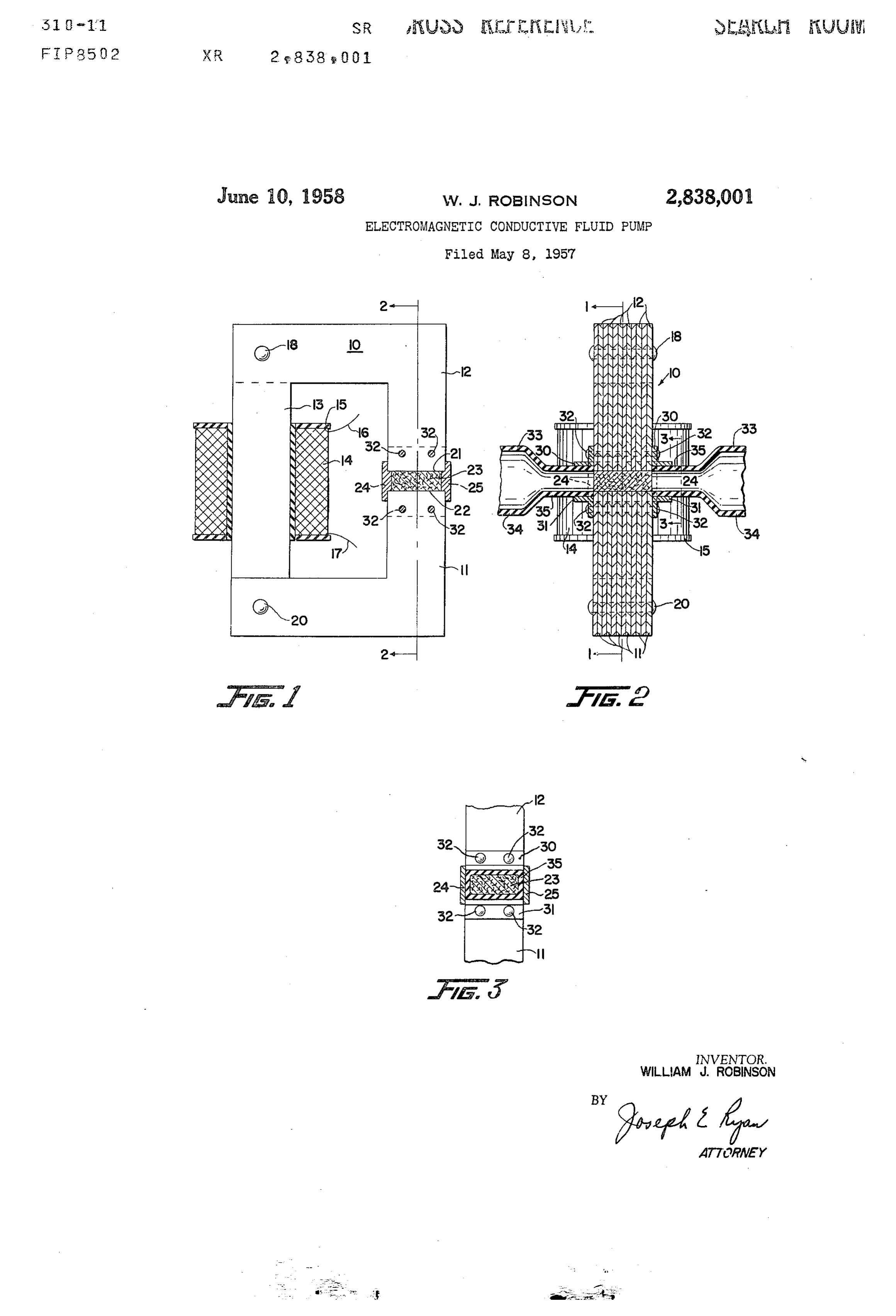
This invention relates to electromagnetic conductive 15 tween by any convenient means. The sides of elec fluid pumps and more specifically relates to a pump hav trodes 24 and 25 fall adjacent the opposite sides of the ing a porous material as its pumping channel. Electro rectangular section 35 and thereby form a fluid type seal magnetic fluid pumps have been long known in the art at each of the opposite sides of the porous material 23 and are often referred to as Faraday pumps. In their adjacent to the poles 21 and 22. It is further under usual form, they comprise a non-conductive tube filled 20 stood that conduit 33 could be constructed of a metal with a conductive fluid which passes through a magnetic lic member as long as the resistance of the metal used field. Inserted in the sides of the tube at right angles was high in comparison to the resistance between elec to the magnetic field are two electrodes which act to con trodes 24 and 25 through the porous material 23 when duct a current through the magnetic field by means of the fluid in the tube. When the current and the mag 25 In contains it the conductive fluid which is to be pumped.
the simplest application however, a non-metallic con netic field are in phase with each other and at Substan duit 33 is utilized and can be constructed of a material tially right angles, a force mutually perpendicular to the Such as plastic or glass. V current and field is created in the fluid. This force acts With the construction described above a continuous to propel the fluid in the tube in the manner of a usual 30 fluid passage is established by means of conduit 33, a type of pump. Sealed junction formed of the brackets 30, 31, and elec An object of the present invention is to disclose an trodes electromagnetic fluid pump that has a unique configura porous 24 and 25. This conduit passes through the material 23 into the second part of the conduit tion for the pumping channel or gap. 33 which has the same sealed junction as the first section A further object is to disclose an electromagnetic pump that has a large opening in its magnetic structure with 35 described. Any conductive fluid placed in one end of conduit 33 passes through the porous material 23 between out the normally encountered high magnetic reluctance. electrodes 24 and 25 out into the other end of conduit These and other objects will become apparent when 33. If the coil 14 is energized a magnetic field will be the following description is considered with the single established across the poles 21 and 22 and the con sheet of drawings, wherein: ductive fluid therefore will be under the influence of Figure 1 is a cross-sectional side view of the novel 40 this magnetic field. When a sintered ferrite is used for pump along lines 1-1 of Figure 2, the porous material 23 it is understood that the mag Figure 2 is a cross-section of a leg of the pump along netic field established across the poles 21 and 22 is large lines 2-2 of Figure 1, and; enoughto-saturate the ferrite and thereby a leakage Figure 3 is a partial view of the pumping channel along 45 flux exists across the voids which exist in the porous ma lines 3-3 of Figure 2. terial 23. The magnetic flux existing in these voids op A C-shaped magnetic structure generally disclosed as erates in conjunction with acturrent which is Supplied 10 is formed of two L-shaped laminations 11 and 12. to electrodes 24 and 25, by means not shown. The cur The laminations 11 and 12 are formed such that by al rent flows from one electrode to the other is at right ternately arranging the stacking of the laminations a 50 angles to the direction of flux. This combination of complete C-shaped structure 10 is formed. On the cen flux and current creates a force in the conductive fluid ter leg 13 of the structure 10 is placed a coil 14 which which impels the conductive fluid in the porous material is wound on an insulated bobbin 15. The coil 14 has 23 in a direction mutually perpendicular to the direction two electrical leads 16 and 17. The coil 14 is preferably of the current and flux. By this arrangement the elec pre-wound on the bobbin 15 and the bobbin 15 is in tromagnetic conductive fluid pump is caused to operate. serted on the leg 13 while the laminations 11 and 12 are 55 It is further understood that the coil 14 and the lami being assembled. Two rivets 18 and 20 are utilized to nated structure 10 could be replaced by a permanent mag clamp the stacks of laminations 11 and 12 into a Sub net having the same C-shaped type of configuration for a stantially solid magnetic structure.
The laminations 11 and 12 of the C-shaped structure 60 ified bycurrent direct type pump. Also the device could be mod utilizing a continuous tube or conduit in place 10 provide two opposing poles 21 and 22 which define of conduit 33. If a continuous conduit is utilized and is an air gap into which is placed a porous material 23. placed in the gap created by poles 21 and 22 the porous The porous material 23 is normally of a magnetic ma material 23 is inserted therein at a point which would terial such as a sintered ferrite. The porous material 23 substantially fills the air gap created between poles 21 65 Electrodeswith coincide the location of the above mentioned poles.
can then be inserted into the sides of the con and 22 and acts to reduce the magnetic reluctance of the duit or welded or soldered with a compatible solder to air gap as well as provide a channel means, as will be the outside depending on the type of construction de seen in the subsequent description. It is further under sired. All of these constructional details are familiar to stood that porous material 23 may be in any form, such. those versed in the art and will not be described in fur as granular or solid, as long as its is pervious to the 70 ther detail here.
conductive fluid to be used. Placed on opposite sides of By the construction disclosed, the fluid passing through the porous material 23 are two electrodes 24 and 25. the porous material 23 has a large area of surface con The electrodes 24 and 25 seal the sides of the pole faces tact and this large area of surface contact allows for the
Page 3
flow of the necessary current between electrodes 24 and ular to said field and fluid flow; said current and magnetic 25. This arrangement further allows for the use of a field causing the conductive fluid to move through the wide gap in the magnetic structure 10 but yields an elec porous material and to thereby propel said conductive tromagnetic conductive fluid pump which has the char fluid.
acteristic of a narrow gap type pump. Many modifica 4. In an electromagnetic pump of the class described tions in the types of material and physical configurations wherein a conductive fluid is caused to flow by an electric could be utilized with the teachings disclosed presently, current and a magnetic field angularly disposed to each and it is understood that the applicant wishes therefore other and to the direction of flow of the fluid: a C to be limited only by the scope of the appended claims. shaped magnetic circuit having a magnetic field induced I claim as my invention: 10 therein; conduit means having a portion thereof disposed 1. In an electromagnetic pump of the class described in the opening of said C-shaped magnetic circuit; said wherein a conductive fluid is caused to flow by an elec portion being substantially filled with a porous magnetic tric current and a magnetic field angularly disposed to material and said porous material transmitting the mag each other and to the direction of flow of the fluid: a netic field across said opening; and two electrodes adja magnetic circuit including said magnetic field; said mag 15 cent to opposite sides of said porous material to conduct netic circuit further having an opening therethrough; con the flow of said electric current mutually perpendicular duit means having a portion thereof disposed in said to said field and fluid flow; said current and magnetic opening; said portion being substantially filled with a por field causing the conductive fluid to move through the ous material and said porous material transmitting the porous material and thereby propel said conductive fluid magnetic field across said opening; and electrode means 20 in said conduit.
adjacent to opposite sides of said porous material to con 5. In an electromagnetic pump of the class described duct the flow of said electric current mutually perpendicu wherein a conductive fluid is caused to flow by an electric lar to said field and fluid flow; said current and magnetic current and a magnetic field angularly disposed to each field causing the conductive fluid to move through the other and to the direction of flow of the fluid: a C porous material and thereby propel said conductive fluid 25 shaped magnetic circuit into which is induced said mag in said conduit. netic field; a porous 'magnetic material substantially filling 2. In an electromagnetic pump of the class described the opening of said C-shaped magnetic circuit and trans wherein a conductive fluid is caused to flow by an electric mitting the magnetic field across said opening; fluid con current and a magnetic field angularly disposed to each duction means adjacent opposite sides of said opening to other and to the direction of flow of the fluid: a mag 30 contain said conductive fluid; and electrodes adjacent to netic circuit including said magnetic field; said magnetic the other opposite sides of said opening to conduct the circuit having an opening therethrough; a porous mate flow of said electric current mutually perpendicular to rial substantially filling said opening and transmitting the said field and fluid flow; said current and magnetic field magnetic field across said opening; fluid conduction means causing the conductive fluid to move through the porous adjacent opposite sides of said porous material to con 35 material and to thereby propel said conductive fluid. tain said conductive fluid; and electrode means adjacent 6. In an electromagnetic pump of the class described to the other opposite sides of said porous material to con wherein a conductive fluid is caused to flow by an elec duct the flow of said electric current mutually perpen tric current and a magnetic field angularly disposed to dicular to said field and fluid flow; said current and mag each other and to the direction of flow of the fluid: con netic field causing the conductive fluid to move through 40 duit means having a portion thereof disposed in said mag the porous material and to thereby propel said conduc netic field; said portion including a porous material; and tive fluid. electrode means adjacent said porous material to pass said 3. In an electromagnetic pump of the class described electric current therethrough; said current and magnetic wherein a conductive fluid is caused to flow by an elec field causing the conductive fluid to move through the tric current and a magnetic field angularly disposed to porous material and thereby propel said conductive fluid each other and to the direction of flow of the fluid: a in said conduit means.
magnetic circuit into which is induced said magnetic field;
said magnetic circuit having an opening therethrough; a References Cited in the file of this patent porous-material substantially filling said opening and transmitting the magnetic field across said opening; fluid 50 UNITED STATES PATENTS conduction means adjacent opposite sides of said opening 2,386,369 Thompson -------------- Oct. 9, 1945 to contain said conductive fluid; and electrode means ad 2,655,107 Godbold –--------------- Oct. 13, 1953 jacent to the other opposite sides of said opening to con 2,686,474 Pulley ----------------- Aug. 17, 1954 duct the flow of said electric current mutually perpendic
Provenance
- Collection
- Cited prior art
- Original PDF
- patentimages.storage.googleapis.com →
- Filed
- 1957-05-08
- Pages
- 3
- Method
- pdftotext (the PDF's own text layer) + pdftoppm 300dpi page scans
- Source
- Google Patents bibliographic record
- Granted
- 1958-06-10
- Inventors
- William J Robinson; Honeywell Inc
- Transcribed from
- patentimages.storage.googleapis.com →