patent · US2484249
Preparation of gas mixtures
11 October 1949
Page 1
Drawing sheet — no readable text.
Page 2
Drawing sheet — no readable text.
Page 3
Patented Oct. 11, 1949 2,484,249
UNITED STATES PATENT OFFICE
PREPARATION OF GAS MIXTURES
Raymond J. Ruble, Beacon, N. Y., assignor to
Texaco Development Corporation, New York,
N. Y., a corporation of Delaware
Application March 19, 1947, Serial No. 735,597
This invention relates to the preparation of desired, to produce product gases in Satisfactory gas mixtures including carbon monoxide and hy yield and having the constituents thereof in de drogen for the synthesis of hydrocarbons, oxy Sired proportions for the synthesis of hydrocar genated compounds and the like, and more par bons and related compounds, or other uses. Still another object of the invention is the pro ticularly to the preparation of Such gas mixtures vision of a novel process for preparing synthesis in an engine of the internal combustion type. gas in an internal combustion engine wherein While attempts have been made heretofore to there is no interference with the ignition and prepare such gas mixtures in internal combustion Substantially no mixing of unreacted feed con engines, difficulties such as undesirable preigni tion have been encountered. In addition, it has () Stituents with the product gases. Another object of the invention is to provide been found difficult to Secure the desired ratio a novel process for efficiently producing synthesis of the carbon monoxide and hydrogen in the gas in an internal combustion engine Coupled product gas for particular uses such as the Syn thesis of hydrocarbons, oxygenated compounds With the production of power by the engine which and the like. For proper functioning of the en 15 is available for work in other phases of the gas generation or the synthesizing process which may gings, it has been found that the ratio of the follow thereafter.
feed constituents and accordingly the yield and Still another object is the provision of a novel ratio of constituents in the product gas, must be process for preparing synthesis gas wherein the confined to a rather limited range. To avoid knock, a very rich mixture has been required. initial reactants such as a hydrocarbon and oxy If too rich a mixture is used, considerable trouble gen are caused to react to form primary oxida is encountered with ignition by reason of Spark tion products, the latter and additional hydro carbon further reacting to form synthesis gas, the plug failures with the result that considerable two reaction phases taking place in the combus feed material is found in the product gas. Where natural gas, consisting chiefly of methane, and : tion chamber of an internal combustion engine. A further object is to provide a novel process oxygen have been used in the feed, it has been for preparing synthesis gaS by means of an in found necessary in some cases to paSS the exhaust gas through a medium such as copper filings, to ternal combustion engine wherein a large range remove the oxygen. Otherwise, explosions of the of different types of reactants can be used in combination with an oxygen-containing gas for product gas may occur. The presence of feed :
constituents such as oxygen in the product gas the efficient production of a good grade of syn is also objectionable in the Synthesis of hydro thesis gas having its constituents in the desired carbons and related compounds because of the proportions.
undesirable effect of the oxygen on the catalyst. Other objects and advantages of the invention The carbureting of feed constituentS Such as 3 Will appear from the following description and claims taken in connection with the attached natural gas and oxygen for use in an internal drawing, wherein:
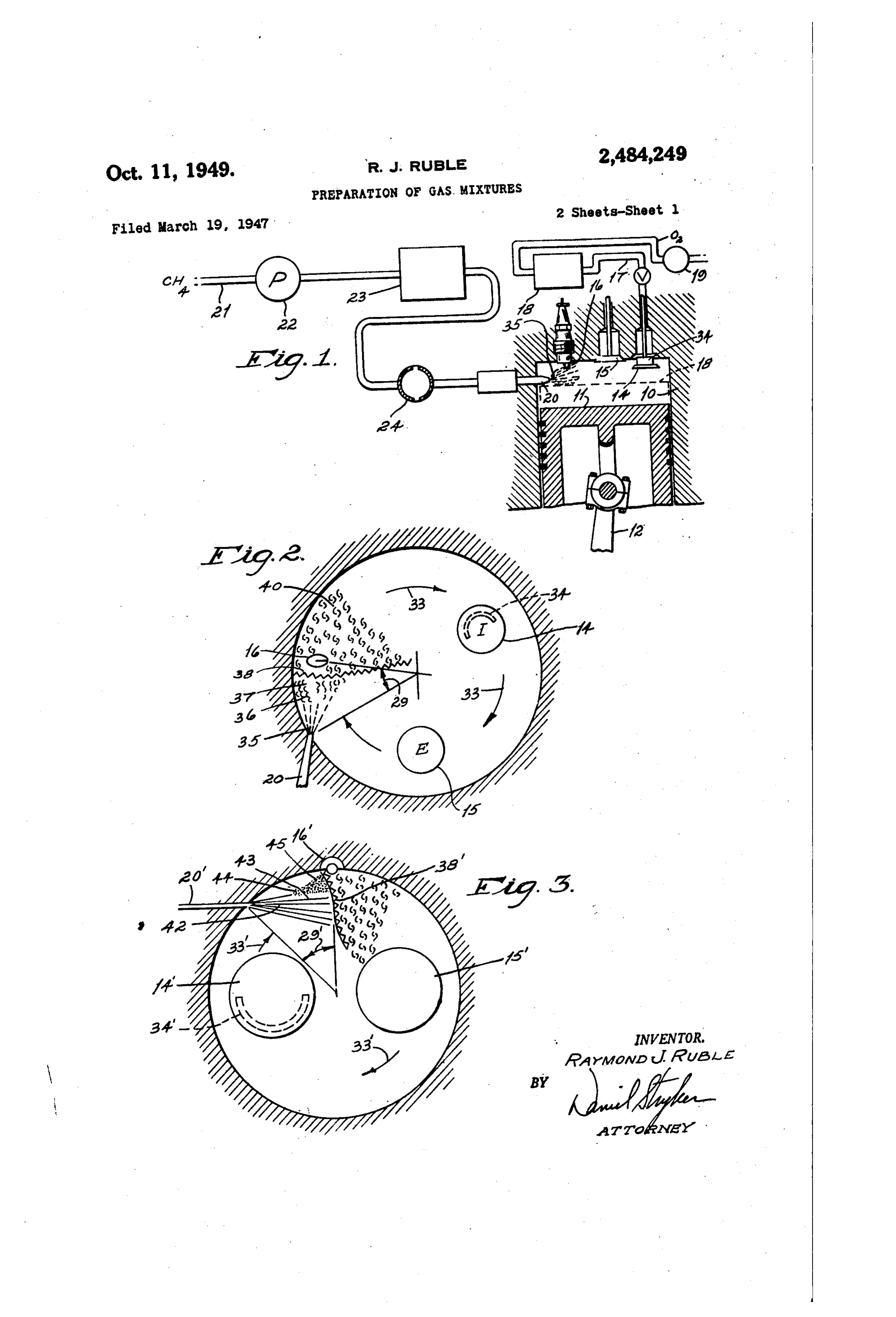
combustion engine has also proven a difficult Figure 1 is a diagrammatic view of an engine problem because of the explosive character of cylinder with the reactant feed and ignition SyS the mixture and the attendant danger of pre ignition and flashbackS. 40 tems therefor.
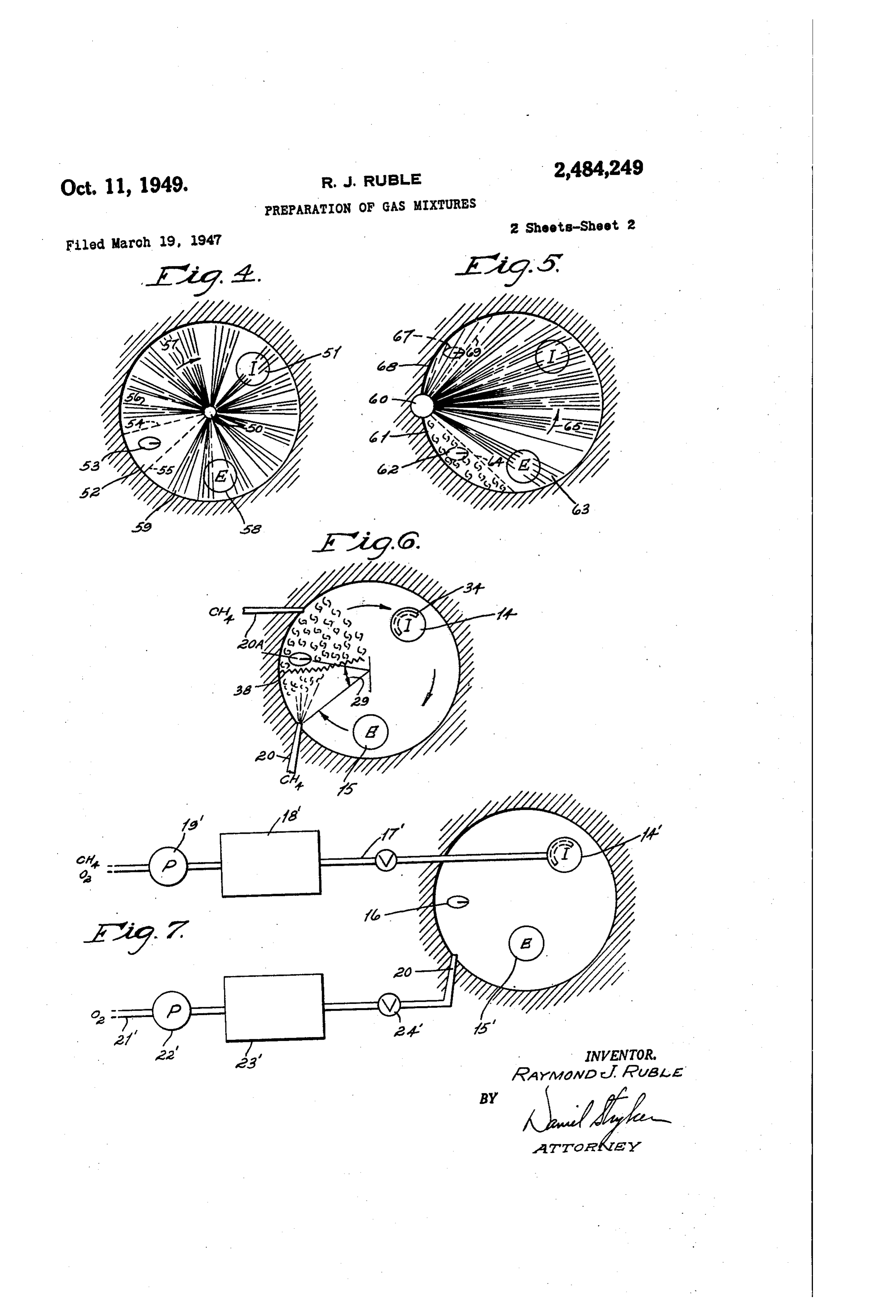
In overcoming the aforesaid disadvantages, it Figure 2 is a horizontal diagrammatic view is an object of the present invention to provide looking upwardly in the cylinder of Figure 1, a novel process for preparing Synthesis gas, con showing the relative locations of the spark plug sisting principally of carbon monoxide and hy and injection nozzle, and the nature of the re drogen, wherein the initial reactants such as hy action taking place in the combustion space. drocarbon and oxygen are caused to react in the Figures 3, 4 and 5 are horizontal views similar combustion chamber of an internal combustion to Figure 2 but of modifications thereof. engine without knocking or preignition and un Figure 6 is a horizontal view similar to Figure 2 der controlled conditions leading to reactions at wherein one of the reactants is introduced at dif a high energy level. 50 ferent Stages in the engine cycle. Another object of the invention is the provision Figure 7 is a diagrammatic view showing a of a novel process for preparing synthesis gas by process wherein one reactant is divided, a portion use of an internal combustion engine wherein fed with the other reactant and the remainder the ratio of the feed constituents can be readily by injection.
varied, and other constituents added thereto, if 55 In brief, the present invention is directed to "
Page 4
processes for the preparation of product gases, the cylinder is caused to react so rapidly after its consisting chiefly of carbon monoxide and hydro initial mixture that it is at all times cushioned gen in different proportions, by an internal com or insulated by a mass of incombustible gas, bustion engine embodying the principles of oper either the oxygen-containing gas, the products of ation disclosed in the co-pending application of the reaction or both. Consequently, the possi Everett M. Barber, Serial No. 513,232, filed De bility of the formation of highly compressed and cember 7, 1943 and entitled Internal combustion heated end gases in other Zones of the combus engine, now abandoned. In the processes in tion chamber which are susceptible to spontane volved herein, the reaction of the feed constitu ints is accomplished in an engine cylinder in Such ous ignition with consequent knock is substan 0 tially eliminated.
manner that knocking or preignition does not Referring to Figure 1, an engine cylinder is in occur, irrespective of the octane number ol dicated at with piston and connecting rod cetane number of the reactants used, the vola 2, the latter extending to the usual crank shaft, tility of the reactants over a relatively broad not shown. The cylinder head is equipped with range, or the compresion ratio; and the propor suitable ports controlled by an intake valve 6 tions of reactants employed are capable of ad and an exhaust valve 5, and an opening receiv justment to Secure a final product gas contain ing a Spark plug 6 connected to any conven ing carbon monoxide and hydrogen in the rela tional ignition System synchronized with the tion desired. movement of piston in well known manner. In brief, this is accomplished by the separate Communicating With intake valve 4 is an oxy feeds of the reactants, by preventing one re gen-containing gas intake line , preferably actant from mixing. With another reactant connected through a preheater 8 with a pump throughout the combustion space, and by caus or compressor 9 capable of compressing the gas ing the reactants to mix in a manner whereby a to a pressure such that the gas can be charged combustible mixture is formed in a predeter to the cylinder at a pressure as high as 100 pounds mined Zone at predetermined times by controlled per Square inch gauge. The port controlled by increments so that the relative advance of the exhaust valve 5 is connected to a synthesis re reaction or flame front, as it might be described, actor of Well known type or to suitable storage traps and compresses Only an incombustible re facilities for the product gas. actant or an incombustible mixture of reactants. 30 A hydrocarbon injection nozzle 20 is mounted This is in contrast to the normal method of oper in a suitable opening in the cylinder head and, as ating an internal combustion engine wherein a shown in Figure 2, is arranged to discharge in a combustible mixture is prepared by carburetion generally tangential direction into the combus and the combustible mixture fed to the combus tion Space of the cylinder. The hydrocarbon is tion space whereby on ignition, which may be Supplied from a suitable source by a line 2 lead premature, the advance of the flame front and ing through a pump or compressor 22, a pre attendant expansion of the gases tends to com heater 23 and a control valve 24 of the rotary or press a portion of the combustible mixture be other suitable type. Pump 22 is designed to fore it is reached by the flame front to an extent force the hydrocarbon into preheater 23, which that under the conditions in the combustion also serves as an accumulator tank or, if desired, space, that portion of the combustible mixture a Separate tank may be provided for this pur isknock, caused to spontaneously ignite with resultant pose, under sufficient pressure such that the hy In the preferred embodiment of the invention, drocarbon, if in liquid form, can be injected at a preSSure of about 2500 pounds per square inch one of the reactants such as an oxygen-contain gauge, or if in gaseous form, can be injected into ing gas, preferably containing 90-99 per cent oxy the cylinder at a pressure of about 2000 pounds gen, is introduced into the combustion chamber per square inch gauge. Dependent upon whether of a cylinder by the usual intake valve and com the hydrocarbon normally exists in the liquid or ressed on the compression stroke. Another re gaseous stage, obvious modifications can be made actant, for instance, a hydrocarbon such as : in the System. The system disclosed is of particu natural gas, consisting chiefly of methane, is in lar advantage in multicylinder engines, since the jected into the compressed oxygen-containing gas Separate cylinders can be supplied through indi at a point of piston travel under conditions such vidual feed lines running from combined pre that a combustible oxygen-hydrocarbon mixture heater and accumulator 23.
is formed at the point of ignition and closely ad 5 5 While oxygen-containing gas is discussed in the jacent the point of injection of the hydrocarbon. present example as being taken in through the The amount, time, and direction of hydrocarbon intake valve and the hydrocarbon through the injection at this stage from injection to ignition injection nozzle, it is to be understood that the is so controlled that the hydrocarbon mixes only two reactants may be reversed and the hydro With a localized portion of the oxygen-contain carbon fed through the intake valve and the ing gas in the combustion space. This first in oxygen-containing gas through the injection noz Crement of injected hydrocarbon with a localized zle. It is also to be understood that the hydro portion of the Oxygen-containing gas forms a carbon may be in a gaseous phase or initially in localized combustible mixture which is immedi a liquid phase capable of being vaporized under ately ignited by a spark or other suitable means thereby establishing a reaction front. If pre of a hydrocarbon, Solid carbon-containingIn ma the conditions existing in the cylinder. lieu ignition occurs, it can only be at this point which terials such as powdered coal, coke, lignite, etc. is so close to the desired point of ignition that no may be used, the term "carbonaceous material' harm is done. The injection of the hydrocarbon being used herein to designate hydrocarbons in is continued during the balance of the injection 70 gas, liquid or Solid phase as well as other carbon period into a narrow zone or zones of the com containing materials such as coal and coke capa busiton chamber immediately in advance of the ble of reacting in the desired manner with oxygen reaction front in its direction of burning. to produce the gas mixtures desired. The net result is that any increment of com Valve 24 functions as a means for regulating bustible mixture undergoing combustion within 75 the quantity of hydrocarbon and the time of its
Page 5
injection relative to the engine cycle. Obviously, the swirling gas and producing a uniform mix valves of other types may be employed, it being ture. Zones indicated by 35 and 36, therefore, only necessary that the action of the valve be Syn can be said to constitute the region of impregna chronized with the movement of piston in well tion of the oxygen-containing gas and the region known manner. of formation of a combustible oxygen-hydrocar Referring to Figure 2, intake valve 4 is pref bon mixture.
erally equipped with a shroud-like member 34 so Just as, or very shortly after the first incre positioned as to direct the incoming oxygen-con ment of injected hydrocarbon reaches the area, taining gas in a tangential direction to produce of spark plug 6 (by which time the combustible a swirling movement of the gas within the Com O oxygen-hydrocarbon mixture has been formed), bustion space as indicated by arrows 33. In Oper a Spark at the electrodes of plug 6 ignites the ation, the gas is charged to the cylinder on the mixture, thereby establishing a reaction front as suction stroke of piston and consequently com indicated by line 38. As shown in Figures 1 and pressed on the compression stroke of the piston, 2, the position of plug 6 is so correlated with the swirling movement of the gas being continued. 5 the position of nozzle 20, and the injection pat It is well established that a high velocity of Swirl tern produced by that nozzle, that the plug elec can be impalted, such that the R. P. M. of the trodes are within the increment of the combus gas swirl at the end of the compression stroke is tible oxygen-hydrocarbon mixture but out of con several times the R. P. M. of the engine. tact with unmixed hydrocarbon whereby igni Near and generally somewhat before the piston 20 tion of this first increment of injected hydrocar reaches top dead center as indicated by dotted bon is insured. The exothermic heat of reaction line 8 (Fig. 1), hydrocarbon is injected from causes rapid heat expansion of the mixture and nozzle 20 into the swirling oxygen-containing gas burning products whereby reaction front 38 as in a generally tangential direction relative to the Sumes a shape such as that shown in Fig. 2. combustion space of the cylinder and preferably 25 Spark plug 6 is spaced from nozzle 20 a sufi in a somewhat upward direction as shown in Fig. cient distance to permit the formation of the in 1 to bring the edge of the injection pattern closely Crement of combustible oxygen-hydrocarbon adjacent the electrodes of spark plug 6. It is mixture during the travel of the hydrocarbon, the to be understood that the upwardly inclined di plug at the same time being sufficiently close to rection of the injection pattern is particularly 30 nozzle 20 to prevent the accumulation within the applicable to this particular embodiment of the combustion Zone or space of any substantial invention where a relatively fiat injection pattern amount of combustible mixture prior to ignition. In the particular arrangement shown, employing is used and the electrodes of the Spark plug are near the top of the combustion space adjacent the a cylinder having a bore diameter of 34 inches, injection nozzle tip. However, where the injec 33 good results can be secured with an included tion pattern is of the cone-shaped type or where angle 29 of about 30-90° and preferably about the spark plug enters the combustion chamber 30-45° between the radii passing through plug 6 with the electrodes closer the nozzle tip, it is not and the tip of nozzle 20, respectively. It is to be necessary that the Spray be upwardly inclined. understood that the injection pattern, the fuel In such case, the injection pattern may be in a A) intensity of the jet, and the velocity of the swirl substantially horizontal plane or inclined down ing gas are altered and correlated for the dif wardly in some cases. Preferably, the hydrocar ferent Spacings for the plug and nozzle tip to bon introduced is highly atomized and, if in the obtain the desired operation. In general, it can form of a liquid, is at such temperature and pres be stated that the included angle 29 should be sure that it flash vaporizes or forms vapor very greater than about 20° and less than 35°. In rapidly, and the resulting hydrocarbon vapor is this manner, the oxygen-hydrocarbon mixture is intimately mixed with the swirling oxygen-con ignited almost as soon as it is formed, eliminating taining gas to form a combustible mixture closely possible preignition, and before an opportunity is adjacent and within a relatively short travel of afforded for the hydrocarbon to mix with the the hydrocarbon from nozzle 20 and about the Oxygen-containing gas throughout any substan time that the resulting combustible hydrocarbon tial extent of the combustion space. The net re oxygen mixture reaches Spark plug 6. Suit is that combustible mixture is produced only As viewed in Fig. 2, the injection pattern from within a localized combustion space and that nozzle 2) is preferably fan-shaped, and as viewed Space is adjacent plug 6. Further, this mixture in Fig. 1, is preferably fiat to generally conform 55 is Surrounded and cushioned by oxygen-contain to the shape of the adjacent portion of the comr ing gas on one side and by incombustible hydro bustion space so as to uniformly impregnate the carbon on the other. Thus, at the beginning of swirling gas as the latter passes slightly beyond ignition, there is no other combustible mixture the point of hydrocarbon injection while simul within the combustion space. The established taneously avoiding objectionable impingement of 60 reaction front 38 tends to travel toward nozzle the hydrocarbon on the cylinder wall and piston. 20. However, the high swirling movement of the The factor of possible impingement is particularly Oxygen-containing gas and other gases in the important where the hydrocarbon is in the liquid combustion Space tends to counteract such rela phase initially and may tend to return to such tive movement of the reaction front with re liquid phase on contact with the cylinder wall 65 Spect to the cylinder wall, so that the reaction and piston. front remains relatively stationary, that is, in a As soon as discharged from the injection nozzle fixed location with respect to the cylinder wall, in its highly divided form as indicated at 35, the fuel nozzle and Spark plug. hydrocarbon begins to mix with the Swirling gas In actual practice the start of hydrocarbon in to form the ultimate combustible mixture. AS 70 jection through nozzle 20 may be between 0° and the injected hydrocarbon moves outwardly to the 75° before top dead center; the degree of advance position indicated at 36, the swirling gas tends being usually set on the best compromise be to deflect the hydrocarbon vapor toward the cylin tween mean effective pressure and reasonable der wall as generally indicated at 37, thereby facil maximum pressures. The spark advance is syn itating the proper mixture of hydrocarbon with 75 chronized with the injection in a manner here
Page 6
inafter discussed in greater detail So that a Spark bustion of the additional increment of combusti of igniting intensity is present at the plug when ble mixture takes place almost as rapidly as the first increment of combustion mixture reach such increments are formed, and that no op es the plug. It is to be understood that the above portunity is afforded for the hydrocarbon to be advance range applies to particular conditions of 5 come disseminated too widely within the com engine size and construction, for example, a 34 bustion Space with possible spontaneous igni inch bore engine having the construction shown, tion and the undesirable formation of carbon. and the settings may be different for other engine The first portions of the combustible mixture designs and constructions. which are rapidly burned at the reaction front An important feature resides in the control of () become substantially incombustible exhaust the quantity of reactant injected before ignition gases which continue the swirling movement and particularly its confinement to a narrow around the cylinder as indicated at 40, Fig. 2. zone of the combustible space, So that the in in this method of operation, another impor jected reactant mixes with only a localized por tant consideration is the proper correlation of tion of the gas therein before combustion of the directional gas movement or swirl with the rate mixture begins. Another important considera of hydrocarbon injection and the injection pat tion resides in the positioning of the Spark plug tern, so as to unifornly impregnate with hydro with reference to the injection nozzle and the carbon the entire volume of oxygen-containing synchronization of the spark with respect to the gaS.
injection so that reaction is initiated in the lo This requires a directed or controlled move calized portion of combustible gas mixture as ment of the oxygen-containing gas within the soon after the beginning of injection as the first combustion space passing the locus of injection, combustible increment reaches the Spark plug. which movement is of a sufficiently high velocity If too much hydrocarbon is injected before the that a complete rotation of contents of the com spark ignites the combustible mixture, then bustion Space can occur within the normal period . there is a possibility of preignition. Further, the of hydrocarbon injection for full power of about mixture disseminates too widely throughout the 30-90 crank angle degrees.
combustion space, and there is Such a large vol The desired directional flow of oxygen-con ume of combustible mixture present therein at taining gas can be conveniently secured by utili the time of ignition that a substantial period of : zing a disc-shaped combustion chamber equipped time is required for the reaction front to progress with means for producing induction swirl of the across this initially-formed combustible Zone. gas as illustrated. While the piston and cylin This approaches the combustion conditions der head are shown in Fig. 1 as being substan characteristic of conventional Otto cycle opera tially flat, one or both may be dished or crowned. tion, wherein it is possible for the advance flame 3.5 It is to be understood that the term “disc-shaped' front to highly heat, and compress unburned mix is used in a broad sense as meaning a combustion ture to the point of Spontaneous ignition before Space which is generally circular in cross section the flame front advances from the ignition means as defined by a geometrical figure spinning on its to the Zone of the aforesaid combustible mixture. axis but which may have various configurations On the other hand, if the spark occurs too in vertical section due to dishing or crowning of soon and is not maintained, then there is...no op the piston or cylinder head or both so long as the portunity for the formation of a combustible combustion Space is devoid of irregular shape mixture during the time the spark is on. Con such as that resulting from communication of sequently, the first increment of combustible the main power cylinder combustion space with mixture will not be ignited and additional hydro an auxiliary combustion chamber. carbon will be injected and combustible mixture An important feature of the present invention accumulated and compressed until spontaneous resides in the fact that the no-knock combus ignition occurs with a high cetane number (low tion or reaction is accomplished in the power octane number) hydrocarbon, or the charge mis cylinder combustion space, and the provision of fires entirely with a low cetane number hydro an ante-chamber or auxiliary combustion space, carbon. Such spontaneous ignition simulates Op or a separate compressor cylinder having open eration on the Diesel cycle and produces a Diesel communication with the main combustion space thump or knock, which operation is not inde Within the power cylinder is rendered unneces pendent of the fuel quality. These objection Sary.
able conditions are avoided in the present in The desired velocity of induction gas swirl is vention without regard to fuel quality by insur Secured by directing the oxygen-containing gas ing proper ignition control and by control of the On the suction Stroke of the piston through a fuel injection and its synchronization with the Shrouded intake valve wherein the shroud extends spark advance in accordance with the relative about 180 around the valve (Fig. 2), the ends positioning of the injection nozzle and Spark plug, 60 of the Shroud being positioned substantially on the diameter of the cylinder, the velocity of gas a radius of the combustion space. With any par swirl, and the injection pattern. As described ticular injection rate and injection pattern for hereinafter, a multiple Spark or continuous Spark a given location of the spark plug, the shrouding of definite duration may advantageously be em of the valve is found to be critical within easily ployed to obviate the necessity for the critical determined limits. For example, either increas Synchronization with the spark advance as is re ing or decreasing the circumferential extent of quired with an instantaneous Spark. the shroud about the valve more than about 10° During the continuance of that portion of the for a particular set up also causes knocking. It compression or combustion stroke or both, which Will be appreciated that such changes in the falls within the period of hydrocarbon injection, 70 Shroud alter the velocity of gas swirl to such an additional hydrocarbon is injected toward reac extent that the same rate of hydrocarbon injec tion front 38 and is mixed with fresh quantities tion with the same injection pattern either over of the Swirling gas to form a combustible mixture or under impregnates the gas passing the injec that is ignited and caused to react as it reaches tion nozzle so that the first increment of com the reaction front. It will be noted that com 75 bustible mixture reaching plug f6 fails to ignite,
Page 7
9. 10 •
However, this difficulty can be overcome by cor is positioned with its electrodes at substantially relating the injection rate and pattern with the the periphery of the combustion space, the in new gas velocity. For example, a 120° shroud Op cluded angle 29' between the radii intersecting erates satisfactorily with a properly correlated the tip of nozzle 20' and the center of plug 6 injection rate and pattern. being approximately 45'.
While certain figures for circumferential ex- . The engine is equipped with the usual exhaust tent and positioning of the Shroud on the intake valve 5' and intake valve 4, the latter having valve have been given above, they are to be under a 180 shroud 34’ positioned with the ends of stood to be by way of example and not by way of the shroud substantially on a radius of the com limitation. The Swirl of the induced gas can also 10 bustion space to impart a Swirling movement be secured by arranging the gas inlet passage so of the air within the combustion space as indi as to discharge generally tangential to the com cated by arrows 33. The proportioning of the bustion space in place of the shrouded valve con valves as to size and location is that customarily struction illustrated. employed in a 3A inch bore cylinder. It will In order to most efficiently effect the desired be understood that in the showing made herein, reaction between the oxygen and the hydro the different elements are shown diagrammati carbon in the combustion space at a high energy cally and do not necessarily show the proportion level and to more completeness, and also provide ing of the valves as to size and location. Ordi maximum power on each cycle, the injection narily the valves are located with their centers pattern is designed to uniformly impregnate the 20 lying on the diameter of the cylinder and are oxygen in its swirling movement. This requires usually of larger size in relation to the cylinder a greater proportion of hydrocarbon toward the diameter shown in the drawings. periphery of the combustion space with progres In the modification shown in Fig. 3 which is sively lesser proportions toward the center. Such particularly designed for the use of liquid hydro uniform impregnation is preferably accomplished carbons, the injection equipment is such as to in the construction shown by arranging the fan produce a penetrating core of atomized fuel par shaped injection pattern to one side of the com ticles 43 on the inner side toward the center of bustion space, so that the outer edge of the pat the combustion chamber with a mist of very tern is close to but does not impinge directly finely divided atomized particles at the outer against the cylinder wall, while the inner edge 30 side adjacent the cylinder wall. The surround of the pattern is offset from the center of the ing mist vaporizes rapidly and mixes with ad combustion space. The expansion of the reac jacent swirling oxygen, which latter deflects a tion products then causes sufficient movement portion of the mixture thus formed and indi of the hydrocarbon, whether initially liquid or cated at 45 toward the electrodes of plug f6'. in the form of gas, toward the center of the com- 3 The plug is thus positioned within the surround ing core of combustible mixture but is out of con bustion chamber or space to effect the desired tact with any injected particles. The operation impregnation of oxygen in this region.
As hereinbefore stated the rate of hydrocarbon of this modification is similar to that previously injection and the injection pattern are coordi described in that the spark plug 6' is synchro nated with the velocity of the Oxygen swirl so 40 nized with the injection advance so as to fire the that any portion of the Swirling oxygen which first increment of combustible mixture as it is impregnated and caused to react on each cycle and reaches the plug, thus initiating combustion with the hydrocarbon receives a regulated establishing reaction front 38'. amount of hydrocarbon to produce an atomic In the operation of this modification, it has O/C ratio within the reaction limits in the pro 45 been found that uniform and finely divided atomization across the entire injection pattern duction of the desired Synthesis gas, the gas is not essential in obtaining knock-free operation, usually desired being in the approximate pro although the reaction efficiency appears to be portions of 1 mol of carbon monoxide to 2 mols somewhat impaired. Having initiated and es of hydrogen. Normally, the rate of hydrocarbon injection is set to give an atomic O/C ratio of tablished the reaction front 38', the additional about 1. For the best yields, an O/C ratio of hydrocarbon injected toward the reaction front 1 to 1.3 is preferred. It will be appreciated that mixes with additional swirling oxygen and reacts proper correlation of the directional flow of oxy therewith substantially as rapidly as a reacting gen with the rate of injection and injection pat mixture is formed. It is probable that the so tern in this method of Operation is an important 55 called penetrating core is in actual operation consideration, since the process depends upon the largely non-existent in the combustion space or rapid formation of a reactible mixture and its evident only as a streak or zone of richer mix reaction substantially as rapidly as formed. Con ture. In any event, the desired no-knock and carbon-free operation is obtained with hydro sequently, the customary non-directional cr tur bulent movement of oxygen within the combus 60 carbons less than 0 and more than 100 octane tion space, which is not equipped with the means using compression ratios up to 10:1 and mani. for creating swirling, is ineffective for obtain fold pressures up to 112 inches of mercury ab ing the no-knock Operation with a fixed locus of solute.
fuel injection. In the modifications described above employing The reaction products produced on each cycle 65 a directed movement of oxygen or oxygen swirl are expanded on the power stroke and discharged with a fixed locus of Swirl, the oxygen swirl has on the exhaust stroke in the customary four several functions. It removes the reaction prod cycle operation. The cycle is then repeated in lucts from reaction fronts 38 and 38' as fast as the manner described. formed so that they are replaced by fresh re Fig. 3 shows a modification wherein a standard 70 actible mixtures and burning of such mixtures is CFR engine having a 3A inch bore single cyl accomplished without objectionable dilution of inder is modified by installing an injection nozzle the reaction products. The directed movement 20' So as to direct the hydrocarbon or reactant of oxygen also brings fresh quantities of oxygen in a generally tangential direction of the com into the fuel impregnation Zone to establish the bustion space, as shown at 42. Spark plug 6 5 uniform impregnation so that a portion of the
Page 8
oxygen is consumed on each cycle. The reaction , nition of the first increment of injected hydro is therefore conducted with high efficiency carbon or rather the mixture formed therefrom throughout the full period of injection on each substantially as soon as that mixture has been cycle. formed, which latter is then present at and in In the forms of the invention shown in Fig contact with the electrodes of the spark. Proper ures 1 and 3 where the spark is close to the in synchronization requires that a spark of igniting jection nozzle tip and the tangential direction of intensity be available at the time this first incre injection is such as to bring an edge of the in ment of reactible mixture reaches the spark plug. jection pattern closely adjacent the plug elec The timing of the beginning of the spark in re trodes, the penetrative force of the jet is suffi 10 lationship to the timing of the beginning of in cient to carry the fuel to the vicinity of the spark jection to accomplish this objective depends on: plug; and the rapidly formed combustible mix (1) The time required for the hydrocarbon to ture along the edge of the injection pattern dif travel from the injector nozzle to the spark which fuses outwardly into contact with the electrodes in turn - depends on the velocity of gas swirl of the plug. However, the oxygen swirl can be 5 and/or the spray velocity as produced by the in utilized to blow combustible or reactible mixture jector and the included angle between the spray into contact with the spark electrodes to insure nozzle and the spray in relationship to the cylin ignition, thereby avoiding direct impingement of der diameter which determines the absolute dis liquid fuel on these electrodes when a liquid hy tance the hydrocarbon must travel between the drocarbon is used which might result in misfire nozzle and Spark plug.
ing and even damping Out of the plug. (2) The time interval during which a spark While in the preferred embodiments above de of igniting potency remains at the spark plug scribed, the hydrocarbon is injected tangentially electrodes, which in turn depends on the charac in the direction of oxygen swirl, this is not es teristics of the ignition circuit and the conditions sential. For example, the hydrocarbon may be at the spark gap.
injected radially or across the oxygen swirl, or The relationships included in (1) above have may be injected against the oxygen swirl. Such already been discussed. The variable under (2) modifications require a proper correlation of the above involves a consideration of the length of hydrocarbon injection rate and its pattern with time a spark of igniting potency is used on each the velocity of the oxygen swirl, the cylinder di 30 cycle, namely, whether it is substantially instan ameter, and the relative positions of the injection taneous, or of a relatively short duration in the nozzle and spark plug, in accordance with the Order of 5-20 crank angle degrees such as may general principles already described. Thus, in be produced with conventional ignition circuits, these various modifications, the oxygen swirl is or whether it is of still longer duration which utilized to blow combustible mixtures into contact : 5 may approximate the time interval of the reac with the plug electrodes while avoiding direct tion phase.
impingement of hydrocarbon particles thereon;
and the injection advance is coordinated with While the present invention can be practiced the spark advance so that the first increment of with a substantially instantaneous spark, this re injected hydrocarbon is fired as the resulting () quires a critical coordination of the spark ad combustion mixture reaches the electrodes. The in Vance with the injection advance. For example, injection pattern is also modified to secure the the construction shown in Fig. 3, employing desired uniform impregnation of the swirling injection in the direction of air swirl, the instan oxygen in accordance with the relative location taneous spark should occur at the plug electrodes of the nozzle and its direction of injection, and at an instant within a range of about 4-10° and the hydrocarbon is injected in a narrow zone in preferably about 6° of crank angle movement fol advance of the reaction front in its direction of lowing the start of hydrocarbon injection. Where relative movement with respect to the oxygen the injection is across or against the air swirl, Swirl. the spark advance is usually in the range of It has been proposed to inject atomized liquid 10-20 after the injection advance for the instan hydrocarbon directly against the electrodes of taneous spark.
an ignition device to produce a high intensity However, it has been found that the conven arc which remains on for the full period of in tional magneto or coil ignition system has a spark jection. In this prior arrangement, an arc of duration of about 5-30 crank angle degrees at high tension and high energy similar to that 5 5 an engine speed of 1800 R. P. M. It has further used in nitrogen fixation furnaces is required to been found that during this period the spark is accomplish the stated purpose of combustion of not always of sufficient intensity to cause the unvaporized hydrocarbon particles. The pres mixture to react, the spark tolerance for a par ent invention is distinguished by the avoidance ticular combustion chamber varying with the of direct inpingement of unvaporized fuel par 60 characteristics and the conditions at the spark ticles in the case of a liquid hydrocarbon or an gap employed. For example, with the construc excessively rich mixture of hydrocarbon gas in tion shown in Fig. 3 and employing an ignition the case of initially gaseous hydrocarbon on the circuit of the magneto type having a spark dura electrodes of the spark plug, by the ability to use tion of about 6 crank angle degrees with a plug a conventional automotive ignition system pro 65 gap of 0.005 inch, and decreasing to a spark dura ducing the customary spark of comparatively tion of about 4 with a plug gap of 0.055 inch, the lower intensity and short duration sufficient to engine Operates satisfactorily without knocking ignite the reactive mixture which first contacts and without substantial carbon formation with the electrodes, and by the use of directional move the following setting of spark advance using a ment of the oxygen with respect to the hydro 70 42 injection advance throughout the runs. With carbon during the period of injection and corn a spark duration of 6, satisfactory operation is bustion. secured with an ignition advance setting of 40-33° An important feature of the present inven BTC, thus giving a spark tolerance of about 7. tion is the proper synchronization of the spark With a spark duration of about 4, successful advance with the injection advance to Secure ig 5 operation is secured with a spark advance setting
Page 9
varying between 37 and 33 BTC, providing a While the conventional automotive ignition Spark tolerance of about 4. circuit functions very satisfactorily and provides In operation with another engine constructed a Spark tolerance which removes the extreme similarly to Fig. 3, except that the spark plug Criticality for exact setting of the spark advance center is moved in about 2 inch from the cir in relation to the injection advance, it will be cumference of the combustion space and the readily appreciated that a continuous spark of included angle between radii intersecting the fairly long duration can be employed, if desired. injection nozzle tip and the spark plug center While the continuous spark can be left on during is 30, a different magneto ignition circuit may the entire engine cycle, utilizing for example a be employed having a much longer spark dura 0 continuous type of spark employed in fuel burner tion than in the previous example. Using a 60° Systems, it is obvious that this arrangement can injection advance throughout the series of runs, be easily Synchronized with engine operation so satisfactory knock-free operation can be secured that the Spark is on only for a selected period of with an ignition advance of 70°-54 BTC for a the reaction phase, and can be turned off during Spark duration of 28, giving a spark tolerance 5 the balance of the cycle. Wherever the expres Sions 'spark ignition' and "ignited by spark' or of about 16°. With a larger plug gap providing Similar expressions appear in the description and a spark duration of about 24, the operative spark advance range can be 70°-60° BTC, providing a claims, it is to be understood that these expres Spark tolerance of about 10'. With a still larger Sions are intended to include any equivalent ar plug gap providing a spark duration of about 22, 20 rangement Such as a glow-wire for igniting the localized combustible mixture.
the operative Spark advance range can be 63-54, While the operations described above, employ giving a spark tolerance at this setting of about 9. ing orderly and directed movement of one of the The above examples are given to illustrate that conventional automotive ignition circuits of the reactants within the combustion space past a magneto type can be employed satisfactorily and 25 fixed locus of injection of the other reactant, are considered preferred embodiments for carrying
Will afford generally a Spark tolerance of about out the no-knock method of operation of the 5-15, depending upon the characteristics of the present invention, it is to be understood that the circuit and the size of the plug gap. Also, this invention is not limited thereto. In order to ob is true of conventional ignition circuits of the coil and breaker type. Moreover, it is to be noted 30 tain the desired relative movement between the reactant taken in the intake and the injected that with the conventional ignition system and reactant during the combustion phase, the modi the given engine construction described imme fications of Figures 4 and 5 may be used, wherein diately above, the maximum spark advance could the locus of fuel injection is progressively moved be set to precede the start of injection by as much in an orderly manner throughout the combustion as 10, while the full retard setting of the spark Space to bring different increments of the in advance could be set as much as 6 after the start jected reactant into mixture with relatively sta of fuel injection, depending upon the size of the tionary or non-directed turbulent intake gas. Spark plug gap. In the above examples, the size Figure 4 shows a modification in which the fuel of the plug gap is purposely varied simply as a injection system and other appurtenances of the convenient means of controlling and altering the engine may be the same as for Figures 1-3, de duration of the spark. As a practical matter, the Scribed above, except that in this case the injec Size of the Spark gap in commercial engines may tion nozzle 50 is positioned centrally of the cylin be set within rather close limits in accordance with conventional practice in the automotive igni is der or combustion space. One reactant is intro duced through a conventional intake valve 5 tion art, and need not be varied to any substan Which may be a simple poppet valve, not provided tial extent. Therefore, the spark duration for a given ignition circuit will be fixed by the charac of the reactant.or other with a shroud
The means for producing swirl injection nozzle is provided teristics of that circuit, and the size of the spark with a plurality of circumferentially arranged gap need not be a variable. Consequently, the ports through which the injected reactant is in spark tolerance for a given engine construction jected in narrow bands or jets in spaced order and a given ignition circuit will be fixed; and the and in Sequence throughout the period of injec maximum spark advance and spark retard posi tions for the given setup can be accurately deter tion.
mined and the Spark setting made accordingly As indicated, the injected reactant, hydrocar Within these limits. It will be obvious from the 55 bon for example, is first injected into a narrow above that, in general, the spark advance for the or localized Zone 52, where it flash vaporizes, if conventional automotive ignition system will be Originally actant in a liquid, and mixes with the other re that particular zone to form a reactible set in accordance with the present invention to approximately correspond with the injection ad mixture adjacent the electrodes of the spark plug 53. This is immediately fired by the spark plug vance or very shortly thereafter. The proper 60 establishing setting for any particular ignition circuit for a reaction fronts on opposite sides of given engine construction can be readily deter the narrow band, as indicated at 54 and 55. Im mined by those skilled in the art in accordance mediately thereafter a second quantity of hydro with the principles set forth above, bearing in carbon is injected from the next adjacent port to mind that a spark of ignitible intensity should form an adjacent body of reactible mixture 56 be present at the plug electrodes at the time the which is immediately ignited by the reaction first increment of injected fuel in the form of a, front 54. In rapid and regular sequence, hydro combustible mixture reaches the plug electrodes, carbon is injected from the additional spaced or not more than about 5-15 crank angle degrees ports into narrow adjacent zones proceeding thereafter such that insufficient combustible mix around the combustion space, so that the reaction. ture has accumulated in the combustion Space front travels in the direction of the arrow 57. It at the time of ignition to permit knocking to is thus seen that hydrocarbon is injected in nar occur. Investigation of various ignition circuits row bands immediately in advance of the reaction for this method of operation has indicated that front, and the resulting reactible mixture is in a relatively high current spark is preferable. mediately consumed by combustion before the
Page 10
hydrocarbon has an opportunity to mix with ously, initiating combustion in localized zone 68 oxygen other than in its localized Zone. Conse with the combustion in zone 6 f. The reaction quently, the reactible mixture in each of the fronts 64 and 69 then rotate about the hydro series of localized zones is at all times surround carbon nozzle as an axis toward each other. The ed and cushioned by incombustible gas, either 5 sequence of hydrocarbon injection from the oxygen or products of reaction. Here again, the spaced ports of the nozzle can be controlled in formation of trapped end gas consisting of re any conventional manner, such as by the ar actible mixture is entirely avoided so that the rangement of sleeve valve described above in Con problem of knock and preignition is substantially nection with Fig. 4. In both Figures 4 and 5 the eliminated. 0. quantity of hydrocarbon injected can be regulated The amount of hydrocarbon injected can be by the setting of the cam through any suitable regulated by the number of ports throughout the external control, and the injection advance can circumference of the injection nozzle through be regulated by the setting of the cam through which hydrocarbon is injected on each cycle. suitable external or automatic control, as is well The upper limit is, of course, injection through understood.
all of the ports. Any conventional valve control Fig. 6 illustrates a modification wherein only for circumferentially arranged ports can be en a portion of one of the reactants such as the ployed to regulate the hydrocarbon injection, hydrocarbon is injected through nozzle 20, the such, for example, as a cam-operated sleeve valve reaction with the swirling oxygen-containing gas sliding over a circumferentially arranged series of proceeding in the same manner as described in ports which are also spaced in the direction of connection with the drawings of Fig. 2 to set up sliding of the sleeve, in the manner of a spiral a reaction front 38. In advance of the reaction staircase. Control of the amount of hydrocar front or clockwise as viewed in Fig. 6, a second bon injected on each cycle is secured by regula injection nozzle 20a is provided for the injection tion of the length of sliding travel of the sleeve of the remaining portion of the hydrocarbon, the valve, and control of the time of hydrocarbon hydrocarbon thus being injected into the reaction injection or injection advance is secured by regul front and disseminated throughout the reaction lation of the cam setting in relation to the en products from the initial reaction of the oxygen gine stroke, all in conventional manner. Fol lowing expansion of the combustion gases, the 30 with the first portion of hydrocarbon, as distin guished from the operation of Fig. 2 wherein the products of reaction are discharged through the so-called primary reaction between oxygen and exhaust valve 58 and the cycle is repeated. a hydrocarbon Such as methane and the so-called Instead of having the reaction front travel in secondary reaction between the reaction products only one direction about the combustion Space in and additional hydrocarbon takes place more or the manner described above, the two separate re less in the same Zone. In the arrangement action fronts 54 and 55 can both be caused to shown in Fig. 6, the secondary reaction between travel in opposite directions. This is accom the hydrocarbon injected through nozzle 200 and plished by controlled injection of hydrocarbon the reaction products takes place in a different from pairs of ports arranged on opposite sides 2One.
of the initial localized combustion zone 52, or in The combined so-called primary reaction and advance of the two reaction fronts as they move the secondary reactions in both cases can be sum : about the combustion space. Thus, hydrocarbon marized as follows:
is first injected into the localized zone 52, Im mediately thereafter, two jets of hydrocarbon are CH4--AO2 CO+2H2 injected simultaneously, or in extremely close se 45 quence, into the zones 56 and 59, and this se Such In such modifications as that shown in Fig. 2, quence of injection is continued while the two re reactions apparently take place substantially action fronts move in opposite directions about together whereas in the modification shown in Fig. 6, they are effected in two different zones.
the combustion space until the oxygen is substan Preferably tially all consumed. In this case, the hydrocar 50 carbon about 20 to 30 per cent of the hydro bon injection ports of the nozzle are arranged to such as natural gas is injected through descend in two series of spiral staircases extend nozzle 26, the remainder of the natural gas being ing in opposite directions from the initial port, injected through nozzle 20d.
and under the control of the sliding sleeve valve Fig. 7 illustrates a further modification based previously described. * , On the arrangement shown in Fig. 1, wherein the Figure 5 shows still another modification in 55 through reactant introduced through intake valve f4 pump '9' and preheater 8' includes an which the hydrocarbon nozzle 60 is positioned at Oxygen-containing gas preferably containing 90 one side of the cylinder and is provided with a plurality of spaced ports for injecting localized to 99 per cent oxygen and a hydrocarbon such as natural gas, the proportions of the mix being hydrocarbon streams in sequence over spaced portions of the combustion space. Hydrocarbon 0 to such that the resultant mixture is not susceptible preignition or explosion under the conditions is first injected into the zone 6 where it is im encountered in the cylinder. The remaining mediately ignited by spark plug 62. Hydrocarbon is then immediately injected from the second port oxygen is introduced through line 2 f', compressor into the localized zone 63 in advance of the re 22' and preheater 23' through valve 24’ to an action front 64 established by combustion in Zone 65 Oxygen injection nozzle 20. In this modification, the introduced through nozzle 20 is in an 6. Thereafter, hydrocarbon is injected in rapid amount to set up a final mixture capable of hav sequence from the other ports, causing localized ing its reaction initiated by spark 6, the remain combustion throughout the other segments of the ing characteristics of operation being as described combustion space in order, and resulting in move 70 in connection ment of the reaction front about the hydrocarbon tion possesses withthe
Figs. 1 and 2. This modifica advantage that the mixture of nozzle as an axis in the direction of the arrow hydrocarbon and oxygen can be brought to a 65 until all the oxygen has been consumed. If relatively high degree of preheat, the resulting desired, a Second Spark plug 67 can be employed reactions correspondingly taking place at a higher for simultaneously, or substantially simultane 76 energy level and hence to a more complete stage.
Page 11
While the invention has been described as ap center of the compression stroke, the second re plied to four-cycle operation, it is to be under actant into a localized portion of said compressed stood that it is applicable as well to two-cycle first reactant within the said combustion space at Operation; in fact the process of the invention a temperature and pressure such that at least a lends itself particularly well to two-cycle opera portion thereof forms with the localized portion tion because there is no necessity for preforming of the first reactant a combustible mixture with only a short travel of the second reactant from the fuel mixture, and this enables the suction the locus of injection, immediately electrically stroke of four-cycle operation to be easily elimi igniting the localized first increment of combusti nated. For example, a two-cycle engine may be equipped with intake ports for directional intro 0 ble hydrocarbon-oxygen mixture as soon as formed and before sufficient of said second react duction of one reactant just above the bottom of art has been injected and has had an opportunity piston travel whereby a swirling movement of the reactant can be developed, as already explained to disseminate more widely throughout the com bustion space, whereby the localized combustible in connection with Figs. 1-3. Poppet exhaust hydrocarbon-oxygen mixture burns and estab valves may be provided at the opposite end of the 5 lishes a flame front traveling with respect to the cylinder for discharge of the product gas. How first reactant within the combustion space and ever, it is to be understood that any conventional construction or design of two-cycle engine can which is confined on the rear side by resulting reaction products, and on the front side by a be readily converted to such method of operation layer of incombustible by Suitable and simple alteration to incorporate injection of the secondgas,
reactant into a narrow the principles of controlled reactant injection in Zone of the combustion space containing com a localized Zone or zones immediately in advance pressed first reactant shortly in advance of the of the reaction front or fronts as described above. flame front in its direction of movement, while To enable better control of the character of the moving the compressed first reactant and locus product gas, it is preferred to control the reactant of Second reactant injection relative to each other entering through the intake valve, such control in an Orderly manner to progressively form addi coupled with a corresponding control of the in jected reactant enabling the proportion of the tional localized portions of combustible hydro carbon-oxygen mixture, immediately in advance initial reactions to be accurately controlled. In 30 of the traveling flame front so that they are. most instances for the preparation of synthesis ignited by said flame front and burned substan gas for the Synthesis of hydrocarbons, oxygenated tially as soon as formed, while maintaining the compounds and the like, it is preferred to use Said confining layer of combustion products at the oxygen in an amount in exceSS of about 25% of rear and the confining layer of incombustible gas that stoichiometrically required to react with a 35 at the front, regulating the relative rate of intro hydrocarbon such as methane to finally produce duction of Said reactants to the internal combus a product consisting essentially of carbon monox tion engine such that the atomic ratio of oxygen ide and hydrogen in a mol proportion of about 1:2. to carbon in the total feed is in the range of about The generation of power as an adjunct to the 1:1 to about 1.3:1, so that the hydrocarbon is generation of the desired gas. mixture such as 40 converted substantially completely into hydro Synthesis gas is of decided advantage in that the gen and carbon monoxide, and recovering the power requirements for the gas generation, in products of reaction so produced.
cluding the power required for initially separating 2. A method according to claim 1 wherein the the oxygen from air or other sources, and the oxygen-containing gas is a high purity stream power required for compressing the reactants, and containing at least about 90 per cent oxygen. the power requirements for other phases of the 45 3. The method according to claim 1 wherein Synthesis process can be supplied by the engine. Said first reactant is a high purity oxygen stream A typical set-up involving an internal combustion containing about 90 to 99 per cent oxygen. engine in Such a process wherein the power re RAYMOND J. R.UBLE. quirements are supplied by the engine is disclosed 50 in the co-pending application of du Bois East REFERENCES (CIE) man and E. M. Barber, Serial No. 722,742, fied The following references are of record in the
Obviously many modifications and variations of file of this patent:
the invention as above set forth may be made 5 UNITED STATES. PATENTS without departing from the spirit and scope Number Name Date thereof and only such limitations should be in 1,107,58 Brownlee et al. ----- Aug. 18, 1914 posed as are indicated in the appended claims. 107,582 Brownlee et al. --- Aug. 18, 1914 I claim: 1,305,579 Wolfard ----------- June 3, 1919 1. The method of preparing a mixture of hy drogen and carbon monoxide by the partial com OTHER REFERENCES bustion of reactants comprising an oxygen-con Richardson, Heating Fuels for Injection En taining gas and a hydrocarbon in an internal gines, The Pennsylvania State College Bulletin, combustion engine having a power cylinder pro The School of Engineering, Technical Bulletin No. viding a combustion space, which comprises in 35 16, Proceedings of the Sixth oil Power Confer troducing one of the said reactants into the said eace power cylinder combustion space, compressing
Said reactant therein, injecting prior to top dead
Provenance
- Collection
- Cited prior art
- Original PDF
- patentimages.storage.googleapis.com →
- Filed
- 1947-03-19
- Pages
- 11
- Method
- pdftotext (the PDF's own text layer) + pdftoppm 300dpi page scans
- Source
- Google Patents bibliographic record
- Granted
- 1949-10-11
- Inventors
- Raymond J Ruble; Texaco Development Corp
- Transcribed from
- patentimages.storage.googleapis.com →