patent · US2857534
Combination electric motor and gyroscopic structures
21 October 1958
Page 1
Drawing sheet — no readable text.
Page 2
United States Patent Office Patented Oct. 21, 1958
centrifugal force, may cause shift in the center of gyra tion of the rotor. This is an important consideration in 2,857,534 the design of gyroscopes for inertial naviagtion systems. It is further found that such a combination electric
COMBINATON ELECTRIC MOTOR AND 5 and gyroscopic rotor construction when emploeyd in con GYROSCOPC STRUCTURES nection with a three-phase stator will operate as an induc tion
Lennox F. Beach, Sea Cliff, N. Y., assignor to Sperry ous Speed or hysteresis motor to bring the gyro up to synchron Rand Corporation, a corporation of Delaware when it locks in as a synchronous motor. I may temporarily increase the voltage supplied to the sta
Application July 6, 1954, Serial No. 441,414 O tor at this time to increase the magnetism of the rotor, 9 Claims. (CI. 310-74) after which the voltage is reduced to the normal voltage. The gyro operates thereafter as a synchronous motor with minimum current consumption.
Referring to the drawings showing several preferred
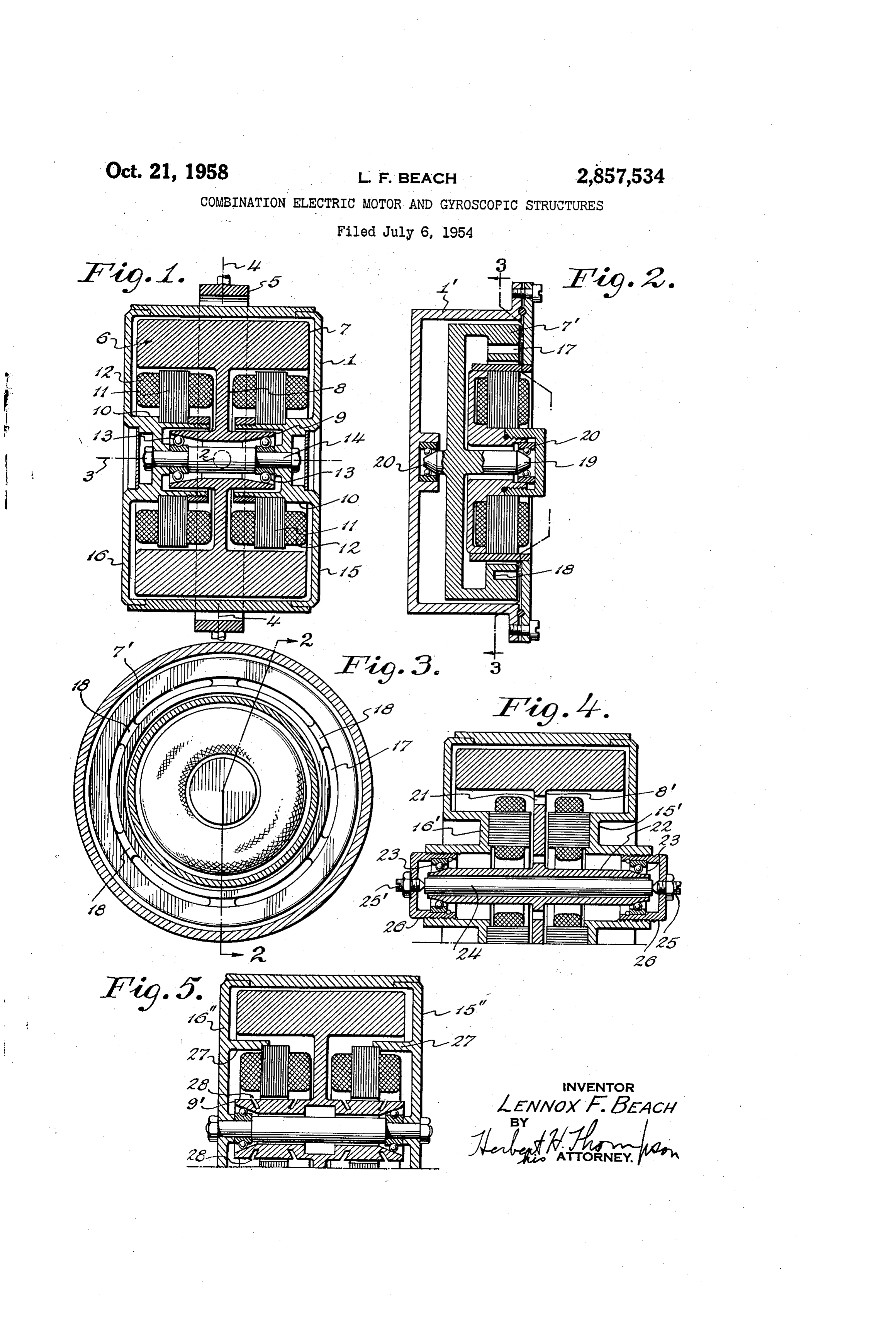
This invention relates to the construction of gyro ro 5 forms of my invention, tors used in sensitive gyroscopic instruments, especially Fig. 1 is a vertical section of a gyroscopic rotor case electrically driven gyro rotors. To obtain the extremely and rotor Which is constructed according to my invention; high accuracy required in sensitive gyroscopic instru Fig. 2 is a similar view of a modified form of rotor; ments, such as directional gyros, it is necessary to elimi 20 Fig. 3 is a vertical section of the rotor case and rotor nate all causes of possible changes in the balance of the of Fig. 2 taken approximately on line 3-3 of Fig. 2; system about all of its axes of freedom as well as to Fig. 4 is a section view of a further modification of eliminate as far as possible friction about such axes. Totor and spinning means in which the drive torque is The most frequent cause of change of shift in the center imparted through the web of the flywheel; and of gravity of the system is temperature change which is Fig. 5 is still a further modification in which the driv apt to cause an unsymmetrical shift in the relative posi 25 ing torque is imparted from the stator to the hub por tion of the parts. tion of the flywheel.
Another cause is lack of homogeneity in the metal mak The gyroscope is shown as enclosed in a rotor case or ing up the rotor. Thus, in most rotor constructions the frame 1 which, it will be understood, is supported for main mass of the flywheel is composed of a heavy metal freedom about at least one axis 2 other than the spin such as iron, while the windings or other parts of the 30 axis 3. If the gyroscope is of the free or universal type, rotor constituting one part of the electric motor con a second axis of freedom 4-4 is provided for the gimbal struction are secured to or built in the rotor. For ex ring 5 which pivotally supports the case 1 on the afore ample, in the induction type motor driven rotor, it is com said axis 2. The rotor proper 6 is preferably formed of mon to make slots in a periphery of the rotor (either a single block of hard, high carbon chrome steel, as in the inner or outer periphery) in which are imbedded 35 stated, which retains magnetism and is shaped to pro the so-called squirrel cage windings usually in the form vide an outer heavy rim 7 connected by the web 8 with of copper rings of rectangular shape. If the self-syn the hub portion 9. This construction provides two under chronous type of A. C. motor is employed, it is usual cut portions of the rim which preferably form the driven to secure or imbed washers or discs of hard, permanent 40 portion of two polyphase A. C. motors. The stator por magnetic steel in the rotor to aid the lock-in or syn tions of each are mounted on projections 10 extending in chronous operation. It is also usual to build up the rotor Wardly from the casing 1 beyond the hub 9 on both sides in several separate parts, namely, the hub, which usually of the web and on each of which are mounted the stator supplies one race for each of the ball bearings, an outer magnetic structure 11 and the three-phase windings 12. flywheel or rim, which usually constitutes the electro mo The hollow hub portion 9 extends in both directions tor portion, and a narrow web connecting the hub and 45 from the web within the inwardly extending projections rim. An example of such construction is shown in the 10 on the case 1 and preferably provide outer races for prior patent to C. E. Barkalow, No. 2,641,132, dated both rotor bearings 13 mounted on the tie shaft 14 ex June 9, 1953, for Gyroscopic Rotor Frame. In this con tending between the two sides 15 and 16 of the rotor struction, it will be noted that two spinning motors are case. Preferably the interior of each end of the hub 9 provided located symmetrically on opposite sides of the 50 is bevelled or flares outwardly as shown, thereby reduc center of support of the gyro whereby thermal expansion ing or eliminating end shift of the rotor during operation. of the rotor and its electromotor parts do not disturb the While the rim or flywheel portion may be solid as balance about its horizontal axis. shown in Fig. 1, I prefer to reduce the amount of steel According to my invention, however, I go much fur in the rotor near the stator so as to concentrate the mag ther than the prior art and reduce the causes of drift of 55 netizing flux from the stator in a particular annular sec the gyro by making the rotor a single homogeneous piece tion of the magnetizable rotor. For this purpose, I have or block of hardened magnetizable steel such as high car shown spaced annular grooves or slots 17 in Fig. 2. bon chrome steel. Preferably, this steel is chosen not which are cut into one face of the rotor, but leaving only to retain its magnetism but to have the proper charac spaced webs 18 joining the outer and inner portions of teristics of uniform hardness so as to serve as the moving 60 the rim 7. It is understood that if this construction is element of suitable bearing means which may be the employed in connection with the double motor drive of outer race of the rotor bearings. Further, no windings Fig. 1, said slots will be cut in the opposite faces. or other inserts of different material are incorporated in Several other modifications are also shown in Fig. 2. the rotor as is the usual practice in the prior art. For Only a single driving motor is shown on one side of the this purpose, I have successfully employed the grade of 65 flywheel. The center of the rotor is shaped in the form steel known as SAE 521.00, having a uniform hardness of a stub shaft 9 instead of a hollow hub, the stub shaft of 62 on the Rockwell "C" scale. By this construction, being ground to a cone shape on each end to provide the I not only lessen errors due to temperature shift but also inner race of the rotor bearings 20. lower the cost of manufacture and give greater freedom In Fig. 4, the drive between the stator and rotor is of design. The main cause of temperature shift is 70 made through the web 8' of the rotor and in this case the eliminated because no parts are pressed or clamped, or two induction stators are mounted to face each other on placed in the rotor which, under the influence of heat or the end plates 15' and 16 and between them extends
Page 3
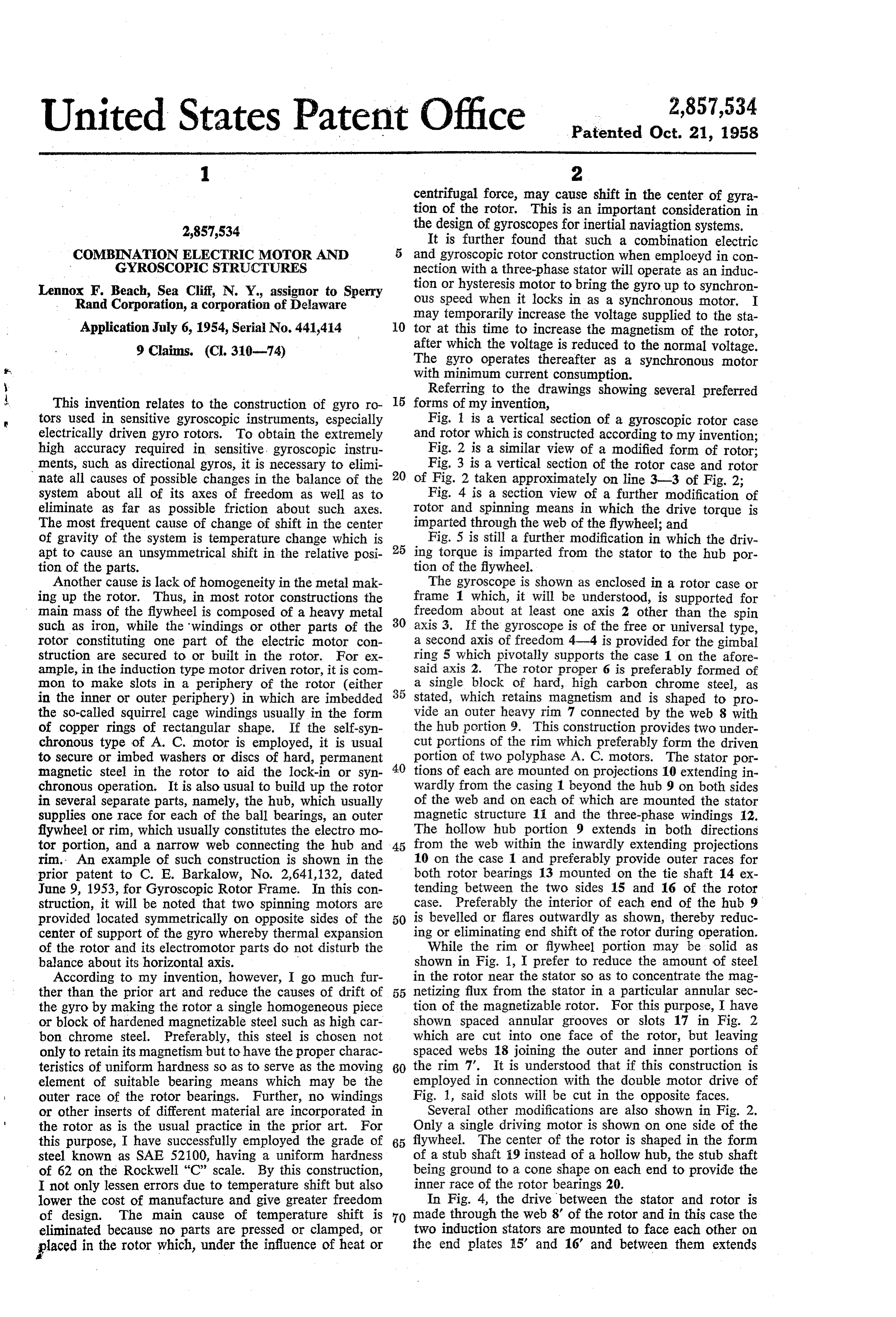
the web. Preferably, the web 8' has cutout portions or rim of the rotor includes means for substantially confin annular slots 21 in a particular section of the web part ing said flux to a relatively thin annular section therein of the rotor for the same purpose as the slots 17 in Fig. and the stator is positioned to supply flux to the thin 2. This modification also shows a different hub con annular section in the rim part of the unitary rotor. struction of the rotor which is" formed as a sleeve 22. 5 6. The combination claimed in claim 4 in which the acting as the inner races of the rotor bearings 23. Proper web of the rotor includes means for substantially con spacing in this case is maintained by compression fining said flux to a relatively, thin annular section therein strut 24 clamped between set screws 25, 25 in the end and the stator is positioned to supply flux to the thin caps 26 secured in the end plates 15', ié'. annular section in the web part of the unitary rotor. in a further modification shown in Fig. 5, the driving 0 7. The combination claimed in claim 4 in which the torque is effected between the three-phase stator wind hub of the rotor includes means for substantially, con ings and the hub portion 9' of the rotor. Two stators fining said flux to a relatively thin annular section therein are shown as mounted on annular webs 27 extending in and the Stator is positioned to supply flux to the thin wardly from the end plates 5'', 16'. Preferably, slots annular section in the hub part of the unitary rotor. 28 are provided in the hub to concentrate the magnetiz 8. A combination synchronous motor and gyroscopic ing flux in the annular section of the hub part of the Structure comprising a frame, a gyroscopic and electric rotor between the slots. motor rotor composed of a unitary piece of hard mag Since many changes could be made in the above con netizable steel having rim, web, and hub parts, one of struction and many apparently widely different embodi which includes an annular section therein for the concen ments of this invention could be made without depart 20 tration of magnetic flux, bearing means on said frame ing from the scope thereof, it is intended that all matter journalling the hub part about the axis of the unitary contained in the above description or shown in the ac electric and gyroscopic rotor, and a polyphase wound companying drawings' shall be interpreted as illustrative Stator for the electric motor fixed to the frame in concen and not in a limiting sense. tric relation to the axis of the unitary electric and gyro What is claimed is: 25 scopic rotor in a position to supply flux to magnetize the 1. A combination consisting of a pair of Synchronous flux concentration section of the unitary piece in which motors and a gyroscopic structure having a case, a gyro the rotor is slotted to provide the flux concentration sec Scopic and dual electric motor rotor composed of a uni tion and, the stator is positioned to supply flux to a con tary piece of hard magnetizable steel having rim, web centration Section in the web part of the unitary rotor. and hub parts one of said parts including means for sub 30 9. A combination synchronous motor and gyroscopic stantially confining the magnetic flux in a relatively thin Structure comprising a frame, a gyroscopic and electric annular section of said one part, bearing means on said motor rotor composed of a unitary piece of hard mag. case journalling the rotor hub part about the spin axis netizable steel having rim, web and hub parts, one of of the unitary electric and gyroscopic rotor, and a pair which includes an annular section therein for the con of spaced polyphase wound stators for the electric centration of magnetic flux, bearing means on said frame motors fixed to the case in concentric relation to the journalling the hub part about the axis of the unitary axis of the unitary electric and gyroscopic rotor with the electric and gyroscopic rotor, and a polyphase wound. web part therebetween in a position to supply flux to stator for the electric motor fixed to the frame in con magnetize said thin annular section. centric relation to the axis of the unitary electric and 2. The combination claimed in claim 1 in which the 40. gyroscopic rotor in a position to supply flux to magnetize. rotor is slotted to provide the flux concentration section the flux concentration section of the unitary piece in and the stators are positioned to supply flux to a thin which the stator is positioned to energize the hub. part. annular section in the web part of the unitary rotor. of the unitary rotor.
3. The combination claimed in claim 1 in which the rotor is slotted to provide the flux concentration sec References Cited in the file of this patent tion and the stators are positioned to supply flux to a UNITED STATES PATENTS thin annular section in the hub part of the unitary rotor. 547,069 Gorges-----------------. Oct. 1, 1895. 4. A combination synchronous motor and gyroscopic 1,913,211 Prince. ----------------- June: 6, 1933: structure comprising a frame, a gyroscopic electric motor rotor composed of a unitary piece of hard magnetizable 50 2,550,571. Litman ---------------- Apr. 24, 1951. Steel having rim, web and hub parts, bearing means on FOREIGN PATENTS - said frame journalling the hub part about the axis of the 21,671 Great Britain ---------------- of 1910 unitary electric and gyroscopic rotor, and at least one 2,120 Great Britain ---------------- of 1913 polyphase wound stator for the electric motor fixed to the frame in concentric relation to the axis of the unitary 55 473,048
electric and gyroscopic rotor in a position to supply 676,046 Great Britain ----------- July 23, 1952. driving flux to one of said parts, and means on said one of said parts for subsantially confining said flux to a rela OTHER REFERENCES tively thin annular section therein. Journal of AIEE, London, August 1948, vol. 95, Part. 5. The combination claimed in claim 4 in which the 60 II, page 418, paragraph9.
Provenance
- Collection
- Cited prior art
- Original PDF
- patentimages.storage.googleapis.com →
- Filed
- 1954-07-06
- Pages
- 3
- Method
- pdftotext (the PDF's own text layer) + pdftoppm 300dpi page scans
- Source
- Google Patents bibliographic record
- Granted
- 1958-10-21
- Inventors
- Lennox F Beach; Sperry Rand Corp
- Transcribed from
- patentimages.storage.googleapis.com →