patent · US4582590
Solar heated oil shale pyrolysis process
15 April 1986
Page 1 — bibliographic record
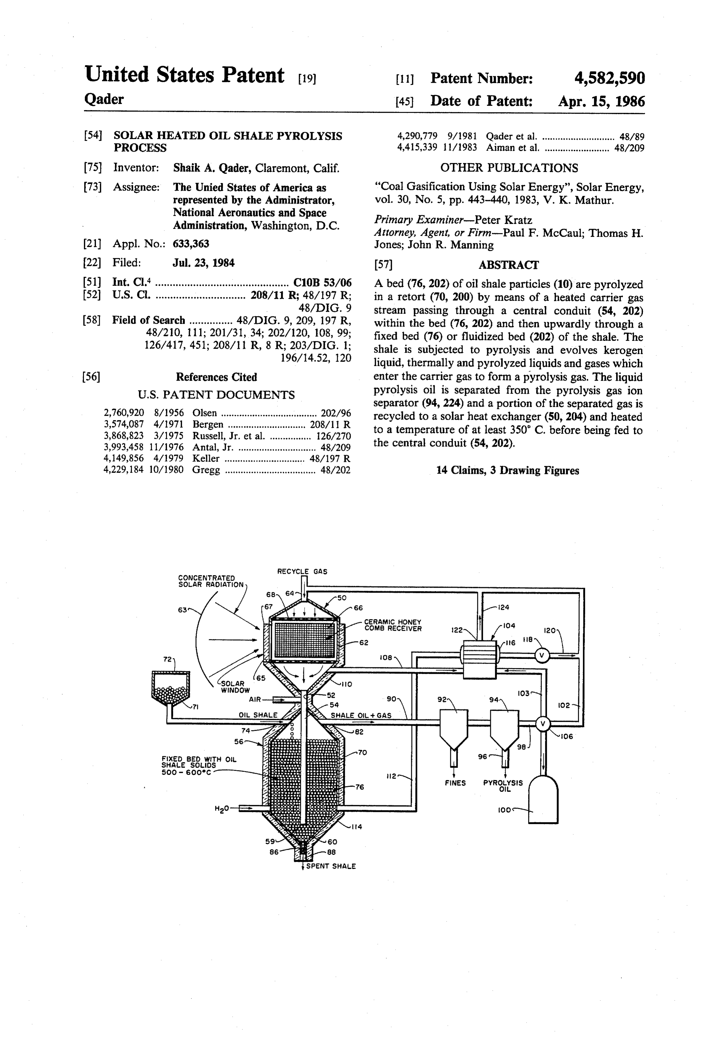
United States Patent (19) 11 Patent Number: 4,582,590 Qader (45) Date of Patent: Apr. 15, 1986 54 SOLAR HEATED OL SHALE PYROLYSS 4,290,779 9/1981 Qader et al. ............................ 4889 PROCESS 4,415,339 1 1/1983 Aiman et al. ......................... 48/209 (75) Inventor: Shaik A. Qader, Claremont, Calif. OTHER PUBLICATIONS (73) Assignee: The Unied States of America as "Coal Gasification Using Solar Energy', Solar Energy, represented by the Administrator, vol. 30, No. 5, pp. 443-440, 1983, V. K. Mathur.
National Aeronautics and Space Primary Examiner-Peter Kratz
Administration, Washington, D.C. Attorney, Agent, or Firm-Paul F. McCaul; Thomas H. (21) Appl. No.: 633,363 Jones; John R. Manning 22 Filed: Jul. 23, 1984 (57) ABSTRACT (51) Int. Cl.' .............................................. C10B 53/06 A bed (76, 202) of oil shale particles (10) are pyrolyzed (52) U.S. C. ............................... 208/11 R; 48/197 R; in a retort (70, 200) by means of a heated carrier gas 48/DIG. 9 stream passing through a central conduit (54, 202) 58 Field of Search ............... 48/DIG. 9, 209, 197 R, within the bed (76, 202) and then upwardly through a 48/210, 111; 201/31, 34; 202/120, 108, 99; fixed bed (76) or fluidized bed (202) of the shale. The 126/417, 451; 208/11 R, 8 R; 203/DIG. 1; shale is subjected to pyrolysis and evolves kerogen 196/14.52, 120 liquid, thermally and pyrolyzed liquids and gases which 56) References Cited enter the carrier gas to form a pyrolysis gas. The liquid
separator (94, 224) and a portion of the separated gas is 2,760,920 8/1956 Olsen ..................................... 202A96 recycled to a solar heat exchanger (50, 204) and heated 3,574,087 4/1971 Bergen .............. 208/11 R to a temperature of at least 350° C. before being fed to 3,868,823 3/1975 Russell, Jr. et al. ... 126/270 3,993,458 11/1976 Antal, Jr. ...... ... 48/209 the central conduit (54, 202).
4,149,856 4/1979 Keller ....... 48/197 R 4,229,184 10/1980 Gregg ................................... 48/202 14 Claims, 3 Drawing Figures
ReCycle GAS
CONCENTRATED
SOLAR RADAON
CERAMIC HONEY
COMB RECEIVEr
Fixed bed with oil
SHALE SOLOS
FNES PYROYsis
SPENT SHAE
Page 2
Drawing sheet — no readable text.
Page 3
Drawing sheet — no readable text.
Page 4
matter is converted to oil upon heating to 500 C., and
SOLAR HEATED OIL SHALE PYROLYSIS the remainder is converted to about 15% gas and 15% PROCESS char. These yields change when oil shale is processed in prototype commercial retorts. Oil yield is reduced from
ORIGIN OF THE INVENTION 5 10% to 30% below modified Fischer assay yields, de The invention described herein was made in the per pending on the process, and char and gas yields are formance of work under a NASA contract and is sub correspondingly increased. ject to the provisions of Section 305 of the National The energy content of the organic matter not con Aeronautics and Space Act of 1958, Public Law 83-568 verted to oil exceeds net process heat requirements for (72 Stat 435; 42 USC 2457). O oil shale retorting. The excess depends on the organic TECHNICAL FIELD content of the shale and the process design, but for well developed processes using a medium grade of shale
The present invention relates to recovery of a liquid (roughly 11 to 15 wt % organic matter) the excess can hydrocarbon fuel from oil shale by retorting and, more 15 be 100% greater than heat requirements. For instance, particularly, this invention relates to the use of a solar the TOSCO II process is based on discarding 100% of heated retort for pyrolysis of kerogen. the char produced from 11% organic matter shale. The The consumption of oil and gas represents about 80% excess can be double or triple this amount when richer of the consumption of fossil fuels in the United States. material is processed.
At the present time, about one-half of the electric power The energy contained in the char and gas by-pro is generated from natural gas and petroleum. Fuels 20 ducts typically cannot be used efficiently. The gas pro other than liquid and gaseous hydrocarbons, such as duced is often greatly diluted with nitrogen and carbon nuclear, hydrogen or methanol are being investigated as dioxide, and the heat content and its efficiency of usage are power sources other than internal combustion en are greatly reduced. In addition, the energy generated gines, such as fuel cells, photovoltaic cells or electric by combustion of the residual char in the rock is consid storage batteries. However, consumers are accustomed 25 erably less than might be anticipated, because of high to using liquid fuels and the supply, distribution, power temperature generation and marketing infrastructure are already in sitions whichendothermic occur when mineral carbonate decompo the char is burned. In short, place. The demand for liquid hydrocarbon fuels for the fuels are in dilute forms and the energy contents power generation and transportation is expected to have low thermodynamic availability. This severely double by the year 2000. 30 reduces or eliminates their commercial value. Areas in There are large deposits of oil shale in the United which western oil shale would be developed contain States and Canada. The organic portion of oil shale has little or no nearby industrial base which could use such a higher indigenous hydrogen content than coal. This fuel, and the gas and char would require prohibitively fossil fuel is a potential source of liquid fuel which would conserve the rapidly depleting petroleum and 35 costly transport. This combined with very low value natural gas resources for other essential uses such as a ments tochar causes and gas in excess of process fuel require be waste disposal problems, rather than sale feedstock for the synthetic rubber and resin industries. able by-products.
The liquid hydrocarbon extract from oil shale could also supply chemical intermediates or serve as a syn The above characteristics of retorting are drawbacks, thetic resin or rubber feedstock. 40 since energy in saleable form is the desired product. Green River oil shale in the western United States is Requirements for heating rock to high temperature, considered by many as second only to coal as the largest excessive conversion of organic matter to char and gas, potential source of fuel in the energy future of the and the low value of the diluted energy content of these United States. In addition, because of its high indige by-products combine to reduce the net saleable energy nous hydrogen content, it is considered superior to coal 45 to to below that contained in the raw oil shale. as a potential feedstock for conversion into liquid fuels. U.S. Pat. No. 3,574,087 to Bergen is an example of an The organic matter in oil shale is conventionally sepa oil shale retorting system in which particles of oil shale rated by retorting from the inorganics with which it is fall downwardly through a column of upwardly flow associated. Temperatures sufficient to crack the organ ing recycle gas. Solar energy has been utilized in the ics are used, and a very-high-nitrogen, unstable "petro- 50 recovery of hydrocarbon fuels. U.S. Pat. No. 4,290,779 leum' is produced. It is forecasted by some strategic discloses the gasification of coal or other biomass mate planners that such oil shale syncrude could enter into rial by passing solar heated recycle gas upwardly the domestic market during the next decade and result through a bed of biomass. The recycle gas is heated by in reduction in the nation's dependency on overseas fuel passing downwardly through an external honeycomb supplies. However, retorting has not yet proven capable 55 jacket surrounding the reactor. of producing a fuel that is truly cost competitive, and Olsen (U.S. Pat. No. 2,760,920) uses a parabolic con present decreases in the price of crude petroleum have centrator to focus solar rays onto a furnace in a coking reduced at least the short term commercial potential of process. Russell, Jr., et al. (U.S. Pat. No. 3,868,823) use all synfuels. a solar concentrator to gasify coal or oil. Antal, Jr. (U.S. BACKGROUND ART 60 Pat. No. 3,993,458) discloses a reactor with a quartz window for solar energy conversion of solid waste into
Oil shale retorting in either above-ground or insitu a synthetic fuel. Keller (U.S. Pat. No. 4,149,856) focuses retorts centers around heating the material, which is solar energy onto coal immersed in water in a solar typically 85% rock, to about 480 C, (900 F) or higher reactor. Gregg (U.S. Pat. No. 4,229, 184) applies focused in a low oxygen environment. The kerogen and bitumen 65 solar rays onto a vertical moving bed of coal and uses a in the rock are decomposed into oil, gas, and a residual heliostat mirror to generate steam. Aiman, et al. (U.S. char which remains within the rock. Under favorable Pat. No. 4,415,339) is another instance of solar coal circumstances in the laboratory, 70 wit% of the organic gasification.
Page 5
Though these solar heating elements are effective for entry into the retorting zone. Sufficient heat is trans use in lower temperature chemical processing, they are ferred to the recycle gas and steam as they pass through not believed to be suited for direct heating of solid the solar heat absorption zone to pyrolyze and extract particles of oil shale to the threshold temperature for the kerogen liquid from the shale. The system of the pyrolysis, usually at least 750 F. (400 C.). 5 invention advantageously avoids the problems caused
STATEMENT OF THE INVENTION
by blackening of the solar input window and also over comes the problem of Zone overheating adjacent the
An improved system for recovery of a liquid hydro solar input window. The flowing gas uniformly distrib carbon fuel from oil shale is provided by the present utes and dissipates heat throughout the heat exchange invention. The system of the invention is energy effi- 10 zone.
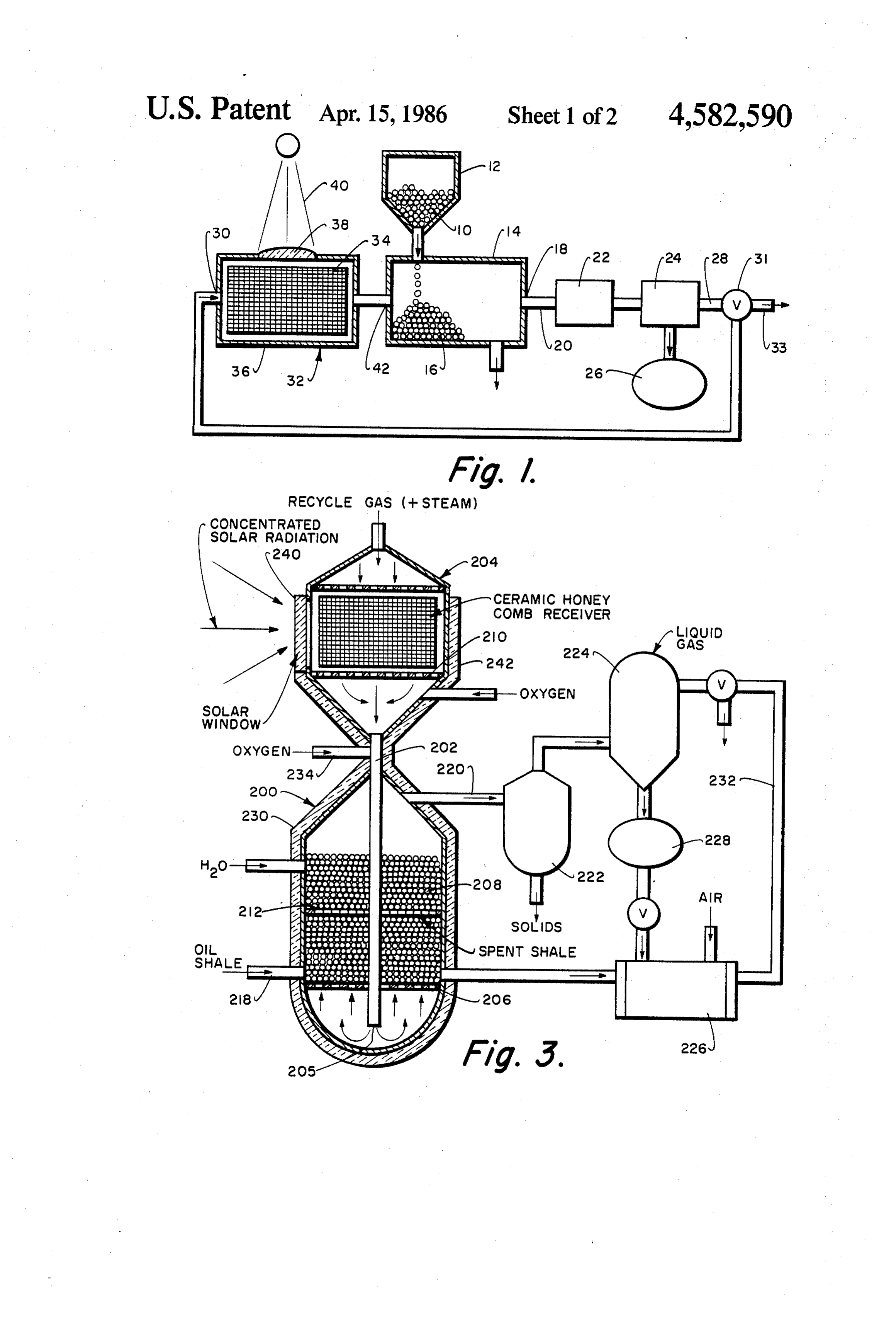
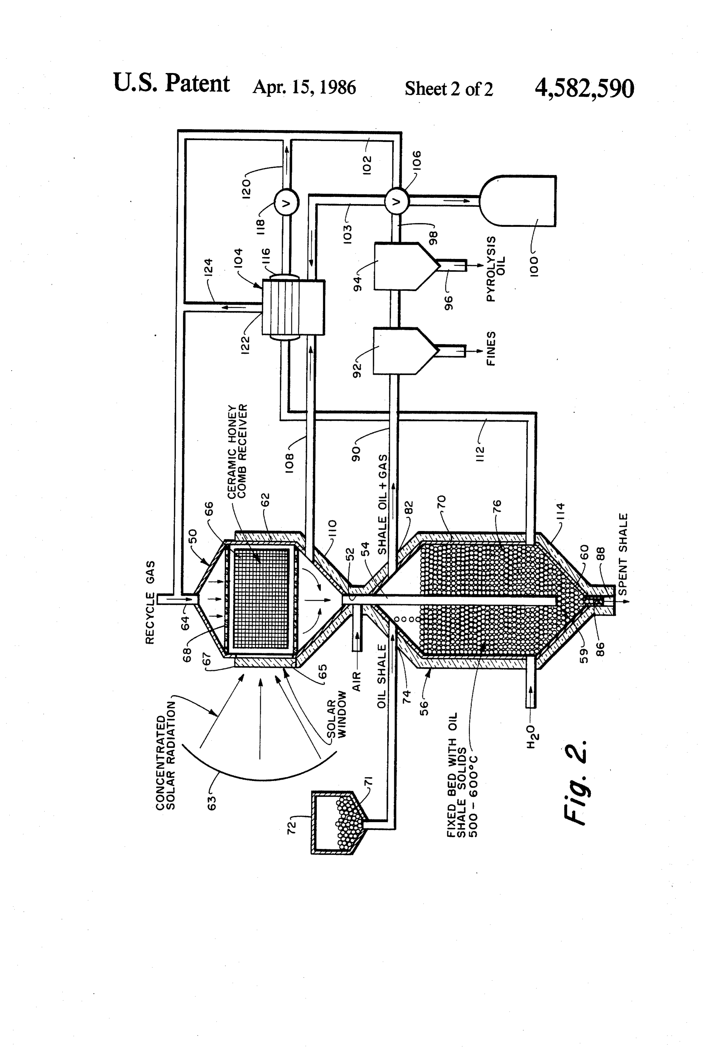
cient and does not require parasitic consumption of These and many other features and attendant advan shale oil to fuel the pyrolysis reactor. The system of the tages of the invention will become apparent as the in invention makes oil shale recovery much more econom vention becomes better understood by reference to the ically attractive. following detailed description when considered in con The oil shale pyrolysis system of the invention com 15 junction with the accompanying drawings. prises a retort reactor for receiving a bed of oil shale BRIEF DESCRIPTION OF THE DRAWINGS particles which are heated to pyrolysis temperature by means of a recycled solar heated gas stream. The gas FIG. 1 is a block diagrammatic view of the oil shale stream is separated from the recovered shale oil and a retorting system of the invention; portion of the gas stream is rapidly heated to pyrolysis FIG. 2 is a schematic view of a fixed bed solar temperature by passing it through an efficient solar assisted system for retorting oil shale; and heater, such as a ceramic honeycomb receiver having a FIG. 3 is a schematic view of a fluidized bed system window for applying solar rays to the honeycomb heat for the solar-assisted recovery of a liquid product from element. At times of low solar flux such as during over shale.
cast conditions, a conventional hydrocarbon fueled DETAILED DESCRIPTION OF THE burner may be utilized to assist in heating the recycle INVENTION gas. Steam, oxygen, air or other oxidizing gas can be injected into the recycle gas before or after the recycle Referring now to FIG. 1, shale particles 10 in storage gas is heated to pyrolysis temperature to combust part bin 12 are processed in a retort 14 by flowing a retorting of the recycle gas and thus raise its temperature before 30 gas heated to a temperature of at least 350° C. through it enters the retort reactor. The combustion reaction is a bed 16 of the shale. The shale is heated by the gas and much more efficient in the absence of carbonate or evolves hydrocarbon gases, inert gases and bitumen and other shale rock fragments. kerogen liquids. The liquid may be cracked into smaller The recycle gas is not diluted with nitrogen and/or molecules of lower viscosity hydrocarbon liquids or carbon dioxide and its heat content and efficiency are 35 gases. The retort gas carries the liquids and gases pro high. The process and system of the invention provides duced out of the retort through outlet 18 and line 20 substantially increased yield of shale oil by the use of into a first solids separator 22 and a second liquid-gas solar thermal heat to preheat the recycle gas and option separator 24. The liquid is recovered and stored in tank ally the steam before introducing it into the bed of shale. 26 while a portion of the product gas in line 28 is recy Though a black body is theoretically an efficient means 40 cled to the inlet 30 of a solar heat exchanger 32 by to heat walls of a retort, the extremely high tempera means of a proportioning valve 31. The remainder of tures achievable by solar concentrators would cause the gas is recovered through line 33. local overheating and weakening of the walls of the The solar heat exchanger 32 contains a porous ele retort vessel. The preheating of the recycle gas is con ment 34 of an opaque, high heat capacity solid such as ducted in accordance with this invention in a solar heat 45 a ceramic honeycomb disposed within an insulated shell absorption zone constructed of an open cell high heat 36. At least one opening containing a window 38 of a capacity refractory material housed in an insulating transparent material resistant to high temperature such shell containing a plurality of windows transparent to as silica or quartz is provided in the shell 36. As the solar energy such as fused silica. High thermal effi solar rays 40 enter the window 38 and are absorbed by ciency is preserved by passing the hot recycle gas coun 50 the ceramic element 34, the recycle gas is heated to tercurrent to the rising retort gas downwardly through retort temperature by the time it enters the inlet 42 of the bed of shale. The present invention overcomes the retort 14. The system of the invention is capable of problems inherent in the previously utilized solar appa operating with little or no sacrificial consumption of the ratus by utilizing a solar heat absorption zone to effi recovered shale oil or hydrocarbon gas to operate the ciently and effectively provide the heat necessary to 55 retort. Furthermore, use of product gas further con carry out retorting of shale, biomass solids and other serves energy since it leaves the retort at a temperature carbonaceous materials. near its inlet temperature.
The solar gasification apparatus of the present inven The size of the oil shale particles and the proportion tion operates on the same general principles as the well of gas recycle depends on the type of retorting system known prior art retorting systems. A retort defining a 60 utilized. From about 10 to 40 percent by volume, usu reaction zone is provided with means for introducing ally about 20 to 30 percent by volume of the outlet gas retorting gas, steam and carbonaceous material into the from the retort is recycled to the solar heat exchanger. retorting zone. Means are also provided for removing Fluidized operation requires finer sized particles of the the gas-liquid product from the reaction zone and for order of about 1 to 1000 microns, suitably about 100 separating recycle gas and solids from the kerogen liq 65 microns for satisfactory fluid bed operation. Fluid bed uid. operation is continuous and the product in retort gas The recycle gas and steam are both preheated by and spent shale can be continuously removed. Fluidized being passed through the recycle solar heater prior to operation also provides efficient heat transfer to the
Page 6
large area, small diameter particles and mass transfer The shale inlet 218 is positioned in this case near the from the particles to the flowing retort gas. bottom of the retort 200 above the screen 206. The However, there are energy and equipment costs re outlet 220 of the retort 200 is connected to a solids quired in grinding oil shale, a fairly hard material, to the separator 222 and a liquid-gas separator 224. The steam very small size required for fluidized bed operation. In 5 generator 226 may be fueled with a portion of the re certain cases, fixed bed retorting of shale particles of covered oil in tank 228. Water is preheated in jacket 230 about 0.1 to 3 inches, usually 0.25 to 1 inch in diameter, and the generated steam can again be fed into recycle may be more economically efficient. line 232.
A fixed bed solar heated oil shale retorting system is Auxiliary heat in this embodiment may be provided illustrated in FIG. 2. The system includes a solar heat 10 by directly injecting air or oxygen through line 234 into exchanger 50 having its outlet 52 connected to a conduit the lower portion of the heat exchanger 204. An excess 54 which is centrally located in the retort 56 with its of oxygen is utilized to prevent soot formation and lower outlet end 59 positioned near the bottom end 60 blocking of the windows 240 of the heat exchanger 204. of the retort 56. The oxygen may be preheated in jacket 242. The heat exchanger 50 has a shell 62 with an upper 15 The reactor can be loaded with finely divided oil inlet 64 and a lower outlet 52. A gas permeable, high shale having a diameter about 100 microns and the heat capacity heating element 66 is disposed within the recycle gas is heated to a temperature of 800 F. to shell 62. An upper distribution plate 68 is mounted be 1000 F. The kerogen releases from the shale and is tween the inlet 64 and the element 66 to provide more 20 pyrolyzed and cracked to molecules within the fuel oil even flow of the recycle gas through the element. Solar range.
radiation can be focused by means of a solar concentra It is to be realized that only preferred embodiments of tor 63. The focused radiation is radiated onto the ele the invention have been described and that numerous ment 66 by means of openings 65 in the shell containing substitutions, modifications and alterations are permissi 25 ble without departing from the spirit and scope of the windows 67.
The retort is an elongated vessel 70 surrounding the invention as defined in the following claims. conduit 54. Oil shale 71 particles are fed from bin 72 into I claim:
the upper inlet 74 and form a bed 76 surrounding the 1. A method of pyrolyzing shale comprising the steps conduit 54. The recycle gas entering inlet 64 is heated of:
by the passage through the solar heated element 66. It 30 passing a recycle gas stream through a gas-permea flows down the conduit 54 out the bottom outlet 59 and ble, high-heat capacity solar-heated heat exchange rises upwardly through the bed 76. The particles 71 will element to form a heated carrier gas, at a tempera be pyrolyzed by the hot recycle gas which causes hy ture of at least 350° C.; drocarbon gases and liquids to be evolved which are passing the carrier gas downwardly through a pipe carried by the recycle gas out the outlet 82. The spent 35 positioned within a bed of shale; shale and char particles leave the vessel 70 through an flowing the gas upwardly through a bed of shale to outlet 86 containing a pressure lock 88. pyrolyze the shale without combustion of the shale The outlet 82 is connected to line 90 containing a and evolve gaseous and liquid hydrocarbons there solids separator 92 for removing fines and a liquid-gas from into the carrier gas to form pyrolysis gas; separator 94 for recovering liquid oil product at 96 and 40 removing the pyrolysis gas from the bed; a gas product at 98. The gas product is distributed to separating liquid product from the pyrolysis gas to storage 100, recycle line 102 and line 103 by means of a form liquid product and gas product; and proportioning valve-assembly 106. The burner 104 is dividing a portion of the gas product into a recycle connected to line 103 and also receives a flow of air gas stream and recovering the remainder. from line 108. The air is preheated in jacket 110 sur 45 2. A method according to claim 1 further including rounding the heat exchanger 50. Water in line 112 is the step of injecting steam into the recycle gas stream. preheated in jacket 114 surrounding the vessel 70 before 3. A method according to claim 1 further including being fed to the tube bank 116. The air in line 108 and the step of combusting a portion of the recycle gas recycle gas in line 103 combust to form combustion gas Stream.
which heats the water in tube bank 116 to steam. The 50 4. A method according to claim 3 in which the por steam is controllably injected by valve 118 in line 120 tion is combusted after passage of the recycle gas stream into the recycle line 102. The exhaust 122 from the through the heating exchange element.
burner can also be fed into recycle line 102 by line 124 5. A method according to claim 4 in which the recy to raise the temperature of the recycle gas as needed cle gas stream is combusted by injection of an oxidizing during times of low solar flux. 55 gas into the stream.
The system can be operated using oil shale particles 6. A method according to claim 1 in which the recy having a diameter from about 0.25 inch to 1.0 inch cle gas stream is composed of 10 to 40 percent by vol retorted with 25 percent recycle gas heated to a temper ume of the gas product.
ature from 500 C. to 600 C. in a ceramic honeycomb 7. A method according to claim 6 in which the recy solar heat exchanger. 60 cle gas is heated to a temperature from 400° C. to 700 A fluidized bed solar heated oil shale retort system is C.
illustrated in FIG. 3. The retort 200 again is connected 8. A method according to claim 7 in which the bed of to the solar heat exchanger 204 by a central pipe 202 shale is a fixed bed and the shale particles have a diame having its outlet 205 disposed below the distributor ter from 0.1 to 3 inches.
screen 206 supporting the fluidized bed 208. An upper 65 9. A method according to claim 7 in which the bed is screen 210 can be utilized to contain fines. A collector fluidized by means of the upwardly flowing recycle gas plate 212 to remove spent shale can be mounted above and the shale particles have a diameter from 1 to 1000 the distributor screen 206. microns.
Page 7
10. A method according to claim 1 further including dizing gas is air and further includes the step of preheat the steps of separating solids from the pyrolysis gas. ing the air by means of heat from the bed and the ele 11. A method according to claim 10 further including ent, the step of separating spent oil shale solids from the bed. 14. A method according to claim 2 in which the steam 12. A method according to claim 1 in which the heat is generated by means of heat from the bed and the exchange element includes a high heat capacity ceramic honeycomb receiver. element.
13. A method according to claim 5 in which the oxi
Provenance
- Collection
- Cited prior art
- Original PDF
- patentimages.storage.googleapis.com →
- Filed
- 1984-07-23
- Pages
- 7
- Method
- pdftotext (the PDF's own text layer) + pdftoppm 300dpi page scans
- Source
- Google Patents bibliographic record
- Granted
- 1986-04-15
- Inventors
- Shaik A. Qader; National Aeronautics and Space Administration NASA
- Transcribed from
- patentimages.storage.googleapis.com →