patent · US1996861
Device for preventing back-firing, capable of being used as theft-preventing devicesfor any applications
9 April 1935
Page 1
Drawing sheet — no readable text.
Page 2
Patented Apr. 9, 1935.
UNITED STATES
PATENT OFFICE
DEVICE FOR PREVENTING BACK-FIRING,
.CAPABLE OF BEING USED AS THEFT-PRE-.
VENTING DEVICES FOR ANY APPLICA-~
TIONS
‘Gaston Dores, Paris, and Lucien Girard, Le .-.Montrouge, France
_ In France October 28, 1929 ©
6 Claims.
This invention relates to “improvements in safety apparatus for: avoiding the return of ignited gases to the carburettor feeding an engine.
The improved ‘safety apparatus according: to
5 the invention is: ‘arranged between the inlet pipe
for the carburetted mixture of the engine and the carburettor. :
This apparatus comprises ‘in combination: :'a
_ casing forming a chamber and having an inlet
0 communicating with the carburettor and an out-
Jet communicating with the ‘engine, a tubular “member having an end which opens in an oppo- “site direction ‘to the inlet and projects into the chamber. in ‘the casing to a point near the outlet, the other end of the tubular member opening to the atmosphere, the outer surface of the tubular member being spaced from the internal wall-of the said chamber to provide an annular passage for the sucked mixture.
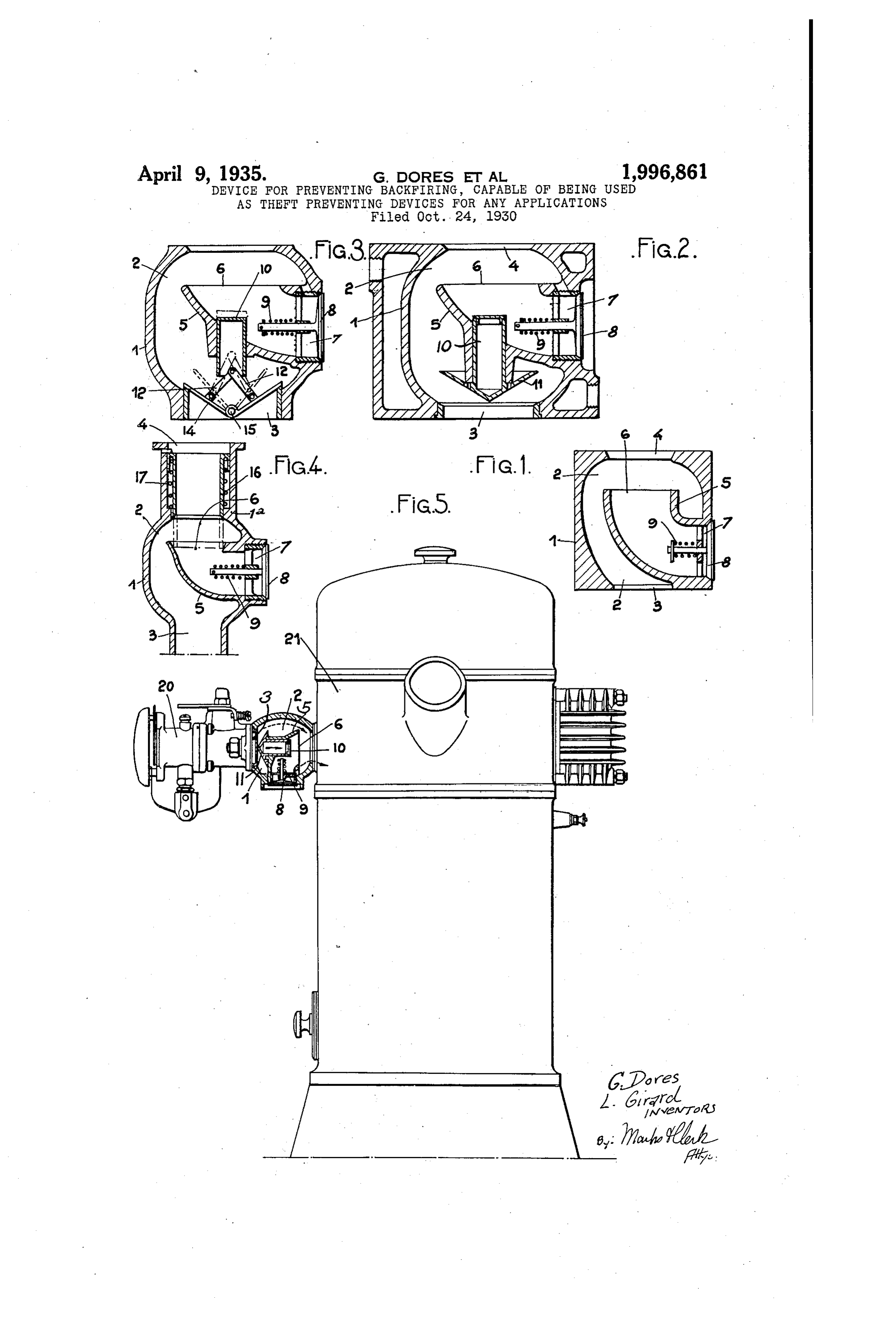
‘The invention. has for further object various forms of construction which will appear from the following description with reference to the accompanying drawings, Siven by way of example only, in which:
Figs. 1, 2, 3 and’4 respectively illustrate, in elevation and ‘axial longitudinal section, four forms of construction of an apparatus according to the invention:
Fig. 5 is an explanatory figure showing the position of the apparatus, illustrated in Fig. 2, between 2 carburettor and an engine fed by this carburettor,
In the first form of construction illustrated in Fig. 1, the apparatus comprises a casing | forming a chamber 2 and having an inlet 3-for the combustible mixture entering the carburettor, and an-outlet-4 for directing the combustible mixture towards the engine. Defiecting means in the form of a tubular member 5, having an open end.6 arranged opposite the outlet 4 and directed in reverse direction to the inlet 2, opens to. the atmosphere through its other end 1 controlled by a valve 8, urged to closed position by. a spring’ 9. The tubular member 5 isso arranged that its outer walls and the inner walls of the chamber 2, limit a substantially annular space in which circulate, during..the normal. feeding period of the engine, the combustible gases.coming from the carburettor, these gases, which enter. the inlet 3,. pass in the chamber 2 and flow, through -the. port 4, towards the engine. During this normal ‘feeding period, the valve 8 closes the:end-7 of the tubular member. 5, in order to avoid. any admission ‘of air.
In case ignited gases coming from the engine should return towards the carburettor, these ig-
nited gases enter the port 4 and the open end 6 of the tubular ‘member 5, they flow through this tubular member 5: towaids the valve 8, which they lift in order. to- be evacuated outside the apparatus.
In the other Figures 2,3 and 4 of the drawings, the. same or similar parts are designated by the Same reference numbers, and the general opera~ tion previously indicated is:the same: in the forms. of construction illustrated in Figs. 2, 3 and 4; the safety apparatus is completed by obtu-
rating members allowing; upon return of the ignited gases; to cut off the communication between .
the engine and the carburettor.
-In the example:shown in Fig. 2, a small piston 10, movable in translation in the tubular. member 5, is rigid with: the valve {i-of which it forms the
During normal feeding of the engine, the valve ff occupies the position’ shown in Fig. 2. In case of return of. the ‘ignited gases, the latter act on the small piston {0-and even-on the valve {f-which then closes the port 3, the ignited gases flowing; through the’ tubular member 5, to the atmosphere, by lifting the valve 8:
In the example shown in Fig. 3, the small pis-_
ton. 10 is connected, by links 12, to two flapping’
members {4 pivoted about a shaft 15. In case of return of ignited gases, the piston 10, on which
these gases act, actuates, through the medium of.
the links 12, the flapping members 14 which obturate the:port 3.
“In the example shown in Fie. 4, the casing 1 comprises. an extension constituted by a guide
member for a tubular. obturator 16 ‘constantly ‘
urged upwardly: by.a weak spring 17. In-case of return of ignited.gases, the tubular obturator “16 is moved downwardly. ‘and. exactly fits against the open end 6 of the tubular member 5; thus cutting off the communication. between: the inlet 3 and the outlet 4 and-constituting; with the tubular.member 5,.a single channel directing the
ignited gases-towards the: exterior, these gases
lifting the valve 8.
‘Fig. 5 shows, by way of-indication, the: position
of the apparatus, illustrated in Fig: 2, between
a carburettor 20 and.an engine 21.
Sie
_ What we claim as our invention and desire to
secure by Letters Patent is:
1. In an apparatus.for security against back- ‘
firing for preventing the ignited gases on the return. path from reaching a carburettor for feed-
ing an engine, the arrangement of an apparatus.
between. the inlet pipe for the.carburetted mixture of the. engine and said carburettor, said appara-
Page 3
tus comprising in combination a casing forming a chamber and having an inlet communicating with the carburettor and an outlet communicating with the engine, a tubular member having an end which opens in an-opposite direction to the inlet
and projects into. the chamber in the casing toa
point near the outlet, the other end of the tubular member opening to the atmosphere, the outer surface of the tubular member being spaced from the internal wall of the said chamber- ‘to. provide
- an annular passage for the sucked mixture,-ob-
turating means associated. with the outlet.end of the tubular member for preventing the admission of air into the ‘said tubular member, but al-
lowing the evacuation from said tubular: member: “the carburettor to the engine, a small piston
to the exterior, so that during the normal run-
ning period, the sucked mixture passes through: the annular space from the carburettor. towards © ‘the engine and, in the case of the return of ig-
nited gases from the engine towards the carbu-
rettor, the inlet of said tubular member entrains and directs said gases to the obturating means and thence to the atmosphere:
2. In-an apparatus for security against backfiring for preventing the ignited gases on the return path from. reaching a carburettor for feeding an engine, the arrangement of an apparatus between the inlet pipe for the carburetted mixture of the engine and said carburettor, said apparatus comprising in combination a.casing forming a chamber and having-an inlet communicating with the carburettor.and an outlet communi-. cating with the engine, a tubular member having an end which opens in.an-opposite direction to the inlet and projects into the chamber in: the casing to a point-near the outlet, the other end of the tubular-member opening to the atmosphere, the
. outer surface of the tubular member being spaced
from the internal wall of the said chamber to provide an annular passage for the sucked mixture, a valve for controlling the end of the tubular member opening in the atmosphere, for preventing the admission of air. into the said ‘tubular member but allowing the evacuation from said.tubular member to the exterior, means for automatically restoring said valve to.its. closing position, a second valve allowing only the passage of the mix-
- ture from the carburettor to the engine, a small
piston being movable. in translation in the tubular member, means for connecting said small.piston
- to said second valve.in such a manner that the
piston forms the stem of the valve so that the return of the ignited gases acting’ on the small piston facilitates the displacement of the second valve for cutting off the communication between said casing and said carburettor’ and so -that, during the. normal. running period, the sucked mixture’ passes through the annular space from the carburettor:towards the engine and, in the
_ case of the return of ignited gases from the engine
towards the carburettor, the inlet of said tubular
member entrains and directs said gases to the first:
valve and thence to the atmosphere..-
3. In an apparatus for security against packfiring for preventing the ignited gases.on the return path from reaching a carburettor for feed-
ing an engine, the arrangément’ of an apparatus .
between the inlet’ pipe for the carburetted mixture of the engine and said carburettor, said apparatus comprising \ in ‘combination a. casing forming a chamber and having ar inlet commuuicating with the carburettor and an ‘outlet.
‘communicating with the engine, a tubular mem-
per having an end which opens in’ an - opposite
direction to the inlet and projects into the champer in the casing to a point near the outlet, the other end of the tubular member opening to the atmosphere, the outer surface of the tubular member being spaced from the internal wall of the said chamber to provide an annular passage for the sucked mixture, a valve for controlling the end of the tubular member opening in the
‘atmosphere, for preventing the admission of air
into. the said tubular. member but allowing the evacuation from said tubular member to the exterior, means. for. automatically restoring said valve to its closing position, two flapping mem-
“bers pivoted about. one and the same fixed shaft
‘and allowing only. the passage of the mixture from
movable: in translation in the tubular member, links for connecting the small piston to said flapping members so that the return of the ignited: gases acting on the small piston facilitates the displacement of the flapping members for cutting off the communication: between. said casing and said carburettor, and so that, during the. normal. running period, the sucked mixture passes through the annular: space from the car-. burettor towards the engine and, in -the case of the return of ignited gases from the. engine towards the carburettor, the inlet- of said tubular member entrains-and directs said gases to the yalve.and thence to the atmosphere.
4. In an apparatus for security against back-: firing. for. preventing the ignited. gases on the
return path from reaching a carburettor for feeding an engine, the arrangement. of an apparatus between. the inlet pipe for the carburetted mixture of the engine and said carburettor, said ap-. paratus comprising in combination a casing form~
ing a. chamber and having an inlet communi-.
cating with the carburettor and. an. outlet communicating with the engine, a tubular member having an end which opens in an opposite direction to the inlet and projects into the chamber in the casing to a point near the outlet, the other end of the tubular member opening to the atmosphere, the outer surface of the tubular member being ‘spaced from the internal wall of the said chamber. to provide an annular passage for the sucked mixture, a valve for controlling the end: of the tubular. member opening in.the atmosphere, for preventing. the admission of -air
into. the said tubular member-but allowing the
evacuation from said tubular member to the ex~- terior, means for automatically restoring said valve to its closing position,.a tubular obturator movable in translation in the outlet of the casing and which connects, during a return of the ignited gases towards the carburettor, with the end of the. tubular member for forming a continuous channel with this tubular member and for directing the ignited gases to the valve and thence to.the atmosphere.
- 5. Apparatus of the character described in-
cluding in combination with the suction pipe of an internal combustion engine, a casing having
an inlet and outlet interposed in the suction pipe
‘and also provided with a relief port communicating with the atmosphere, valve means for the
port acting to normally prevent admission of outside air and deflecting means means within the casing and extending from the port to a point near and’ opposite the outlet and acting to allow the normal passage of liquid fuel from the inlet to the outlet but entraining a back firing charge from the outlet and directing it. to the re-
Page 4
lief port so that it will be exhausted by the valve means. : ;
6. Apparatus of the character described in-
. cluding in combination with the suction pipe of
an internal combustion engine, a casing having an inlet and outlet interposed in the suction pipe and also provided with a relief port. communicating with the atmosphere, valve means for the port acting to normally prevent admission of outside air and deflecting means within the casing and extending from the port to a point near and
opposite the outlet and acting to allow the normal passage of liquid fuel. from the inlet to the
outlet but entraining a back firing charge from
the outlet and directing it to.the relief port, and: -additional valve means mounted in the’ casing for allowing the normal passage of liquid fuel.
thereto: but closing under the action of a back firing charge to prevent. the passage of the latter rearwardly through the inlet. -
GASTON: DORES..
LUCIEN GIRARD: .
Provenance
- Collection
- Cited prior art
- Original PDF
- patentimages.storage.googleapis.com →
- Filed
- 1930-10-24
- Pages
- 4
- Method
- pdftoppm 300dpi + tesseract 5 (eng)
- Source
- Google Patents bibliographic record
- Granted
- 1935-04-09
- Inventors
- Dores Gaston; Girard Lucien
- Transcribed from
- patentimages.storage.googleapis.com →