patent · US1934703
Electrical sterilizing apparatus
14 November 1933
Page 1
Drawing sheet — no readable text.
Page 2
Patiented Nov. 4, 1933 1934,703
UNITED STATES PATENT DFFICE
ELECTRICAL STERILIZANG APPARATUS
Sennetta E. Goidea, Spokane, Wash., assignor to
Ray-dio-Ray Corporation, Spokane, Wash.
Application April 29, 93. Seria Ro. 533,864
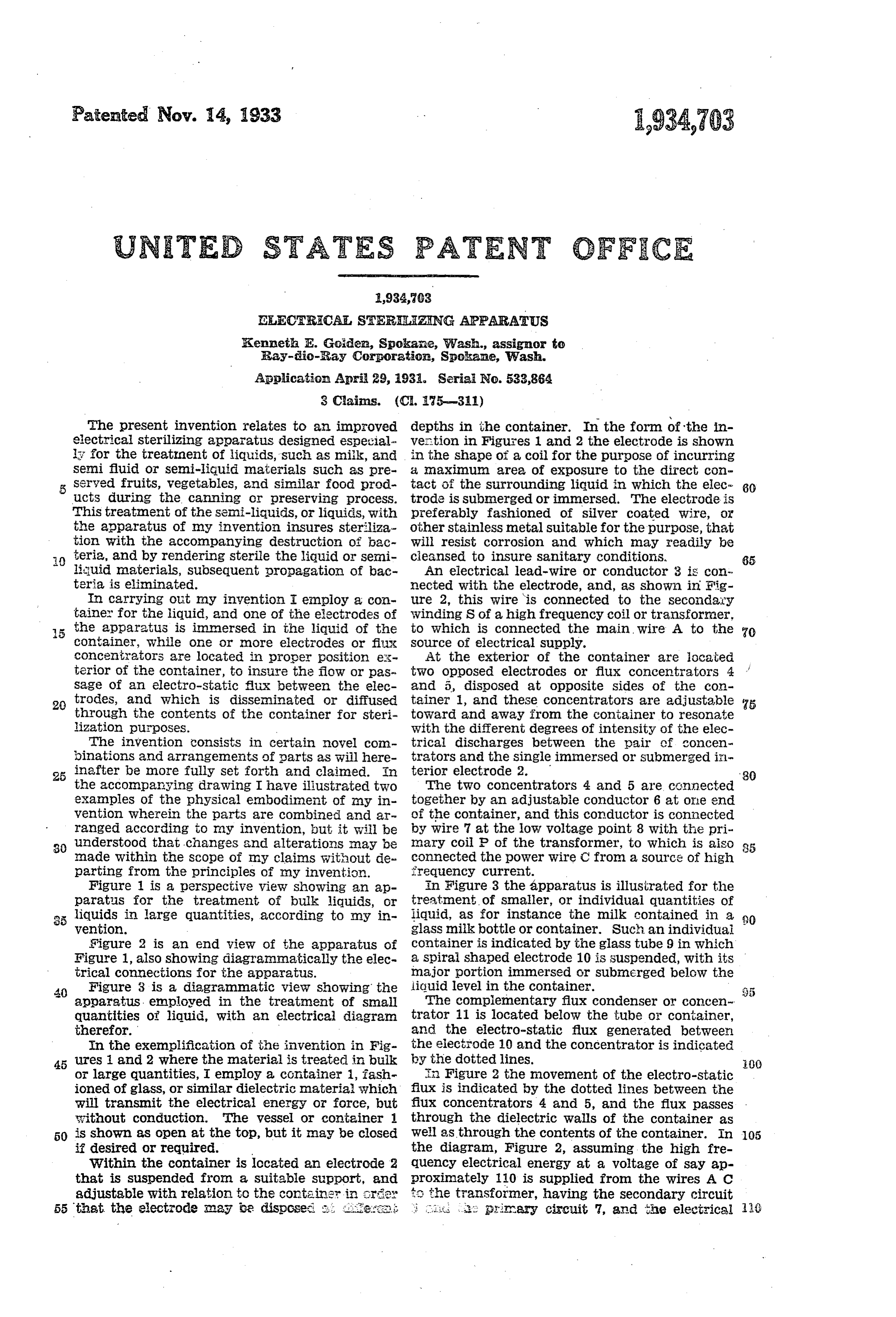
The present invention relates to an improved depths in the container. In the form of the in electrical Sterilizing apparatus designed especial. Weation in Figures 1 and 2 the electrode is shown is for the treatment of liquids, such as nik, and in the shape of a coil for the purpose of incurring Seni fluid or Semi-liquid materials such as pre a maximum area of exposure to the direct con erved fruits, vegetables, and similar food prod tact of the surrounding liquid in which the elec 80 uctS during the canning or preserving process. trode is submerged or immersed. The electrode is This treatment of the Seni-liquids, or liquids, with preferably fashioned of silver coated wire, or the apparatus of my invention insures steriliza Other stainless metal suitable for the purpose, that tion with the accompanying destruction of bac Will resist corrosion and which may readily be teria, and by rendering sterile the liquid or semi cleansed to insure sanitary conditions, 65 liuid materials, subsequent propagation of bac An electrical lead-wire or conductor 3 is con. taria is eliminated. nected with the electrode, and, as shown in Fig In carrying out my invention employ a con ure 2, this wire is connected to the secondary tainer for the liquid, and one of the electrodes of Winding S of a high frequency coil or transfornier, 5 the apparatus is immersed in the liquid of the to which is connected the main Wire A to the container, while one or more electrodes or fix Source of electrical supply.
Concentrators are located in proper position ex At the exterior Of the container are iocated terior of the container, to insure tha flow or pas tWO Opposed electrodes or flux concentrators 4 Sage of an electro-static flux between the elec and 5, disposed at opposite sides of the con 2 trodes, and which is disseminated or diffused tainer 1, and these concentrators are adjustable 5 through the contents of the container for steri toward and away iron the container to resonate lization purposes. With the different degrees of intensity of the elec The invention consists in certain novel com trical discharges between the pair of concen iinations and arrangements of parts as will here trators and the Single immersed or Submerged in 25 inafter be more fully set forth and claimed. In terior electrode 2. 30 the accompanying drawing I have iliustrated two The tWO concentrators 4 and 5 are connected examples of the physical embodiment of my in together by an adjustable conductor 6 at Oile end vention wherein the parts are combined and ar of the container, and this conductor is connected ranged according to Iny invention, out it will be by wire at the low voltage point 8 with the pri. 3. understood that changes and alterations may be nary coil of the transformer, to which is aiso 35 inade Within the scope of my claims without de connected the power wire C from a source of high parting from the principles of my invention. ifrequency current.
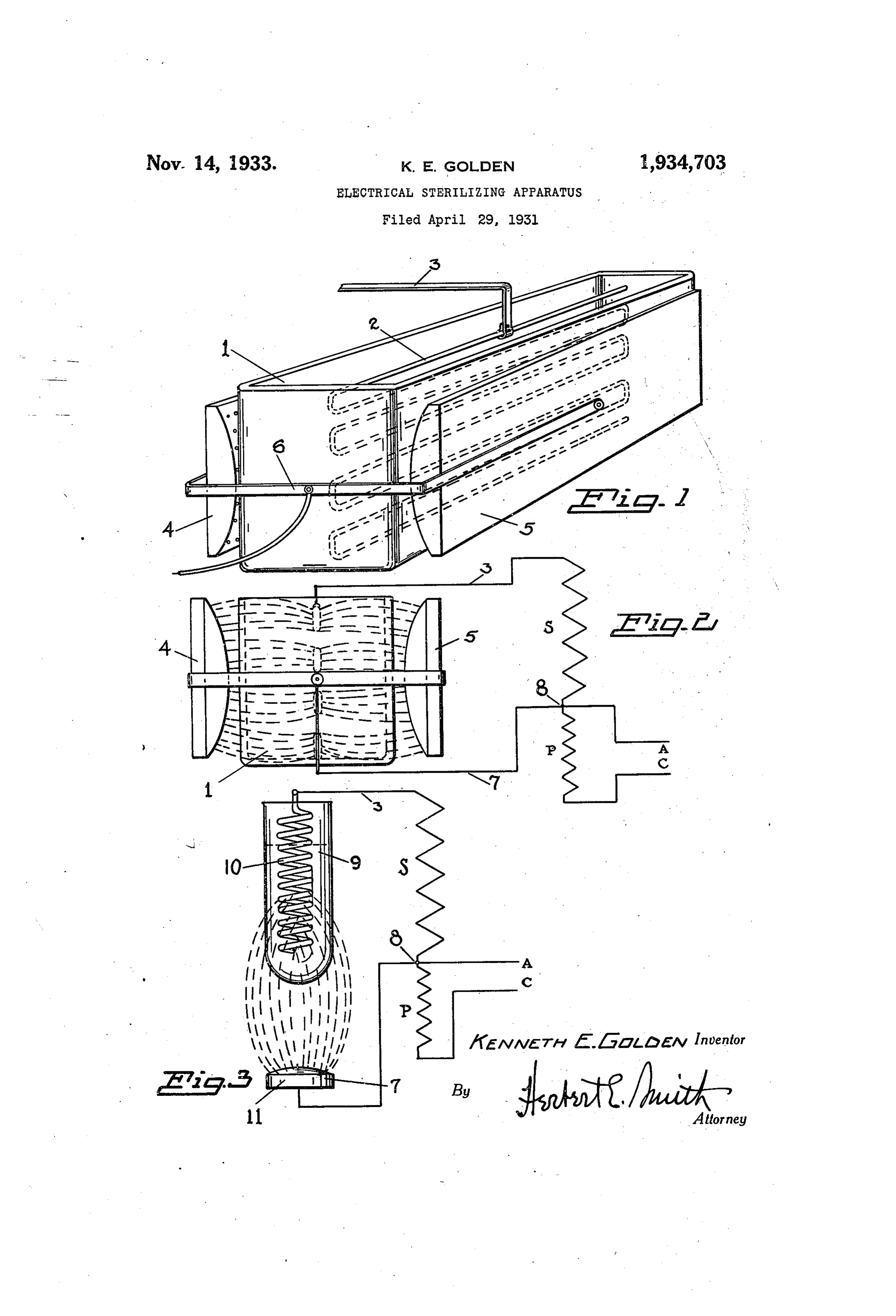
Figure 1 is a perspective view showing an ap in Figure 3 the apparatus is illustrated for the paratus for the treatment of bulk liquids, or treatment of smaller, or individual quantities of liquids in large quantities, according to my in liquid, as for instance the milk contained in a 90 Wention. glass milk bottle or container. Such an individual Sigure 2 is an end view of the apparatus of container is indicated by the glass tube 9 in which Figure 1, also showing diagrariannatically the elec a Spiral shaped electrode 10 is Suspended, with its trical connections for the apparatus. major portion immersed or submerged below the 20 Figure 3 is a diagrammatic view showing the liquid level in the containe. apparatus. employed in the treatment of Smal The complementary flux condenser or concen quantities of liquid, with an electrical diagram trator 11 is located below the tube or container, therefor. and the electro-static flux generated between in the exemplification of the invention in Fig the electrode 10 and the concentrator is indicated ures i and 2 where the material is treated in bulk by the dotted lines.
or large quantities, I employ a container 1, fash in Figure 2 the movement of the electro-static ioned of glass, or similar dielectric materia which flux is indicated by the dotted lines between the will transmit the electrical energy or force, but flux concentrators 4 and 5, and the flux passes Eithout conduction. The vessel or container through the dielectric walls of the container as 50 is shown as open at the top, but it may be closed well as through the contents of the container. In 05 if desired or required. the diagram, Figure 2, assuming the high fre Within the container is located an electrode 2 quency electrical energy at a voltage of say ap that is suspended fron a Suitable support, and proximately 110 is supplied from the wires A C adjustable with relation to the contai X {2 the transformer, having the secondary circuit 55 that the electrode may be disp.csesi 2 piirary circuit 7, and the electrical i
Page 3
energy may thus pass through the Secondary cir I claim as new and desire to secure by Letters cuit to the electrode and return through the con Patent is:- centrators 4 and 5 and the conductor or connec . . An apparatus for electrically sterilizing tion 6, by Way of the primary circuit to the low liquids comprising a dielectric container and an voltage point 8 of the transformer, thus Supply electrode therein, a complementary flux-concen ing the energy for sterilizing the contents of the trator exterior of the container, a Source of elec 8 Container. trical energy, and connections between said elec Thus, in actual practice, and utilization of the trode and Source and between the concentrator apparatus of my invention, I find that an electro and Source.
0. static flux is produced for the destruction of bac 2. An apparatus for Sterilizing liquids com teria, which bacteria, like other materials, have prising a dielectric container and an electrode 85 a fundamental point of vibration, or point of therein, a pair of opposed flux-concentrators ex resonance, with the electrical energy. The fre terior of the container, a source of electrical en quency of the oscillation of the energy is approx ergy, connections between said electrode and 5 imately 470,000 cycles per second, and the voltage Source, and between the concentrators and Said 90 of Said oscillations is approximately 65,000 volts SOUCe.
for securing the best results in use of the appa 3. An apparatus for Sterilizing liquids compris ratus. By the employment of the apparatus here ing a dielectric container and an electrode there in described and illustrated, bacteria, and other in, a pair of opposed flux-concentrators exterior 20 deleterious matters are destroyed by means of the of the container and a Secondary circuit, a trans radiant, electrical energy, developed through the former for high frequency electrical currents in 95 employment of the high voltage, electrostatic flux said circuit, and a primary circuit connected with concentration or field. a suitable Source of Supply. Having thus fully described my invention, what KENNETH. E. GOLDEN. 25 Ob
Provenance
- Collection
- Cited prior art
- Original PDF
- patentimages.storage.googleapis.com →
- Filed
- 1931-04-29
- Pages
- 3
- Method
- pdftotext (the PDF's own text layer) + pdftoppm 300dpi page scans
- Source
- Google Patents bibliographic record
- Granted
- 1933-11-14
- Inventors
- Kenneth E Golden; RAY DIO RAY CORP
- Transcribed from
- patentimages.storage.googleapis.com →