patent · US20050091981A1
Vehicle with a combustion engine and a fuel cell device
5 May 2005
Page 1 — bibliographic record
(19) United States (12) Patent Application Publication (10) Pub. No.: US 2005/0091981A1
Saliger et al. (43) Pub. Date: May 5, 2005 (54) VEHICLE WITH A COMBUSTION ENGINE Publication Classification
AND A FUEL CELL, DEVICE
(76) Inventors: Rainer Saliger, Bamberg (DE); (52) U.S. Cl. ................................................. 60/716; 429/12 Thomas Heid, Renchen-Ulm (DE);
Markus Koberstaedt, Uslar (DE)
Correspondence Address: (57) ABSTRACT
STRIKER, STRIKER & STENBY
103 EAST NECK ROAD
HUNTINGTON, NY 11743 (US) A vehicle having a combustion engine, a fuel cell device having a fuel cell unit, a compressed air Storage for Supply (21) Appl. No.: 10/976,062 of a compressed air, a Supply conduit provided between the (22) Filed: Oct. 28, 2004 fuel cell unit of the fuel cell device and the compressed air Storage, for Supplying the fuel cell unit with compressed air, (30) Foreign Application Priority Data and a further Supply conduit provided between the combus tion engine and the compressed air Storage for Supply of the
Oct. 29, 2003 (DE)..................................... 103 50 5504 combustion engine with compressed air.
Page 2
Drawing sheet — no readable text.
Page 3
Drawing sheet — no readable text.
Page 4
Drawing sheet — no readable text.
Page 5
Drawing sheet — no readable text.
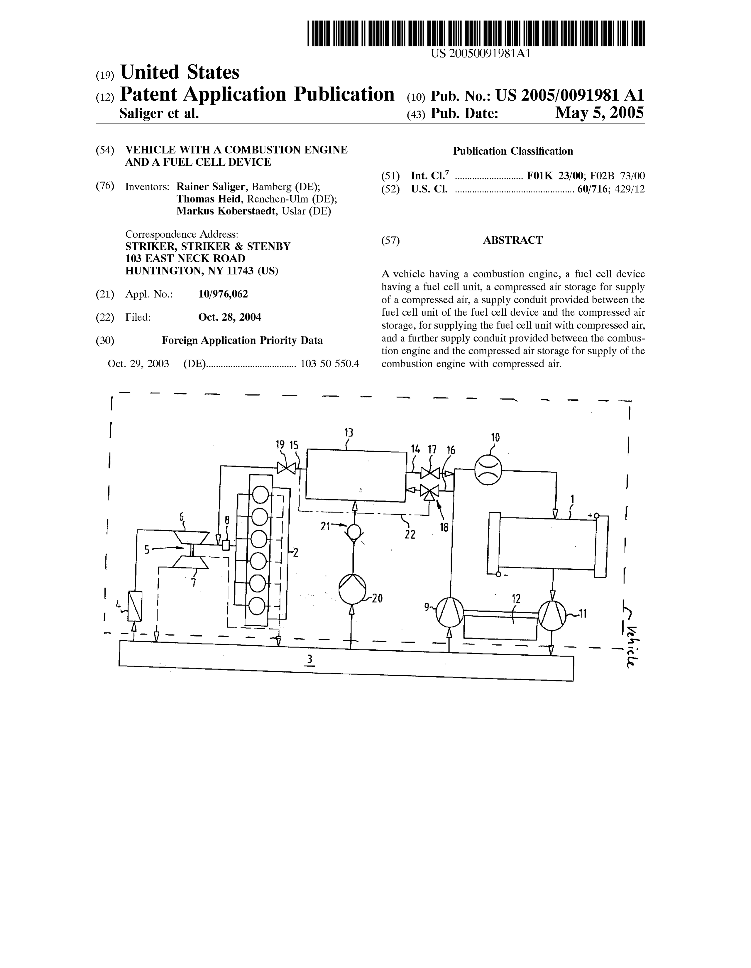
Page 6
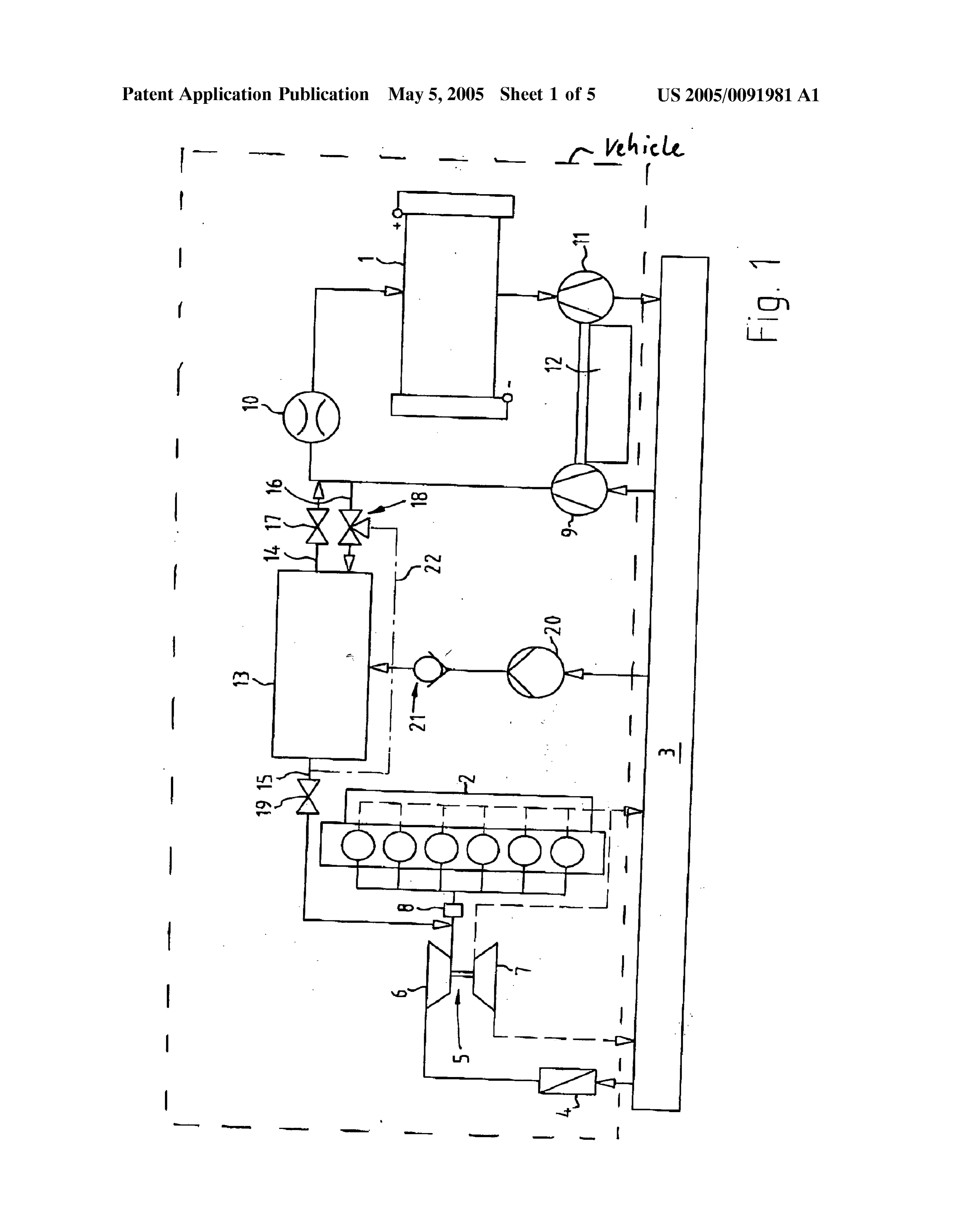
Drawing sheet — no readable text.
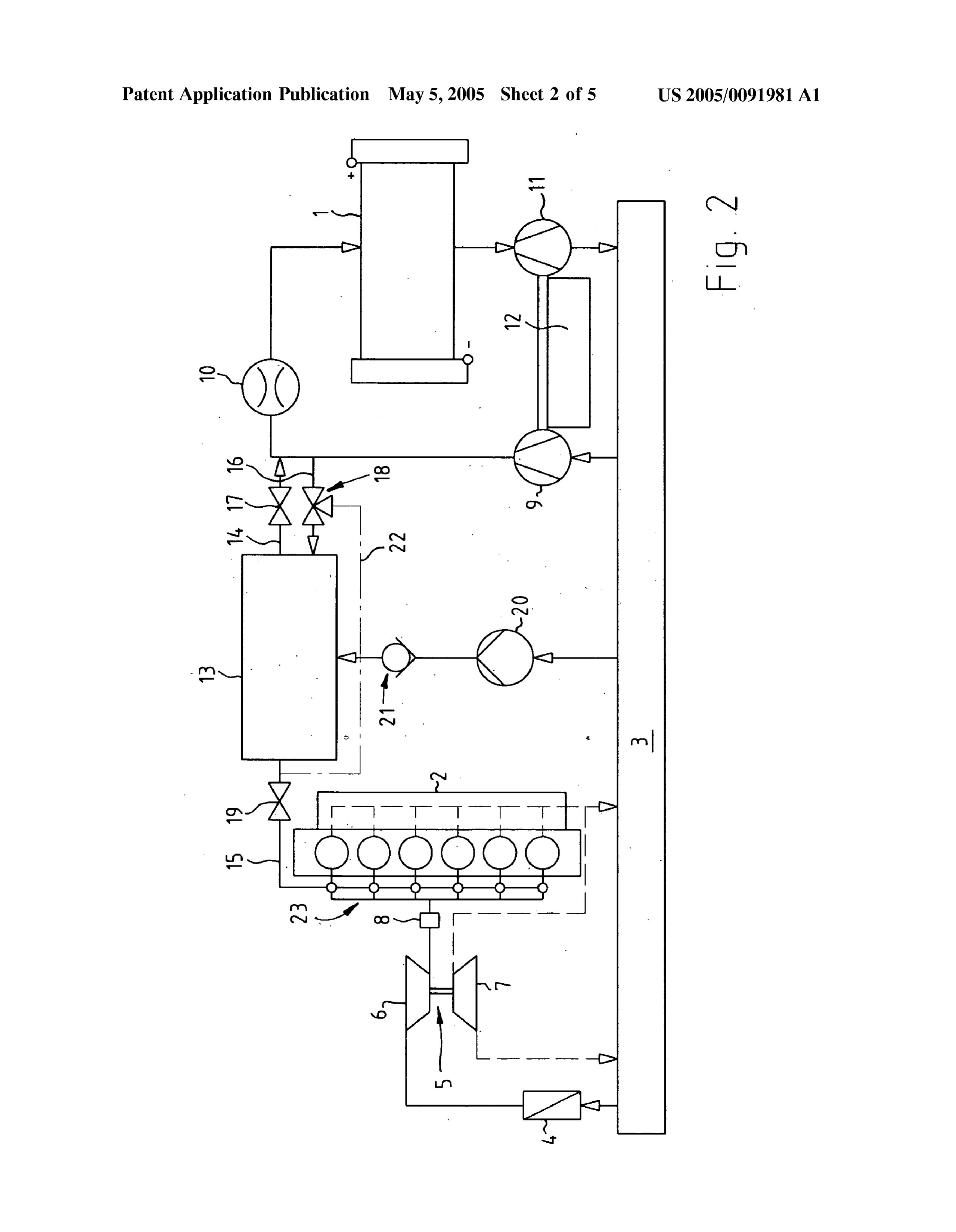
Page 7
US 2005/009 1981 A1 May 5, 2005
VEHICLE WITH A COMBUSTION ENGINE AND A with the prior art are reduced and Simultaneously the FUEL CELL DEVICE response behaviors of the System in case of dynamic load requirement are optimized.
BACKGROUND OF THE INVENTION
0009. In keeping with these objects and with others 0001. The present invention relates to a vehicle with a which will become apparent hereinafter, one feature of the combustion engine and a fuel cell device. present invention resides, briefly Stated, in a vehicle, com prising a combustion engine; a fuel cell device having a fuel 0002 Vehicle drives, in which a fuel cell is utilized for cell unit; a compressed air Storage for Supply of a com production of electrical energy in connection with one or pressed air; a Supply conduit provided between Said fuel cell Several electric motorS became known particularly in con unit of Said fuel cell device and Said compressed air Storage, nection with a so-called “Zero Emission Vehicle'. Such for Supplying Said fuel cell unit with compressed air; and a vehicles are partially provided with a hydrogen tank, for further Supply conduit provided between Said combustion Supplying the fuel required for the operation of the fuel cell. engine and Said compressed air Storage for Supply of Said In other embodiments additionally a device for fuel reform combustion engine with compressed air. ing is provided, in which conventional fuel which usually is available in form of hydrocarbons is chemically cracked, 0010) A vehicle in accordance with the present invention whereby the hydrogen required for the operation of the fuel is characterized in that a further Supply conduit for Supply cell is produced. ing the combustion engine with compressed air is provided between the combustion engine and the compressed air 0003. The overwhelming number of vehicles is however Storage.
driven in foreseeable time as before by reciprocating piston motors, which are provided additionally with a current 0011. By means of the further, second supply conduit, generator in form of a dynamo, to Supply electrical periph which extends in particular from a joint compressed air eral devices with energy. Storage, a multiple use of at least the compressed air Storage both for the fuel cell unit and also for the combustion engine 0004 Modern motor vehicles are designed in increasing can be realized. For example the combustion engine is a numbers with a plurality of consumers, for providing addi conventional reciprocating piston engine and/or a hydrogen tional functions to improve the motor control, the comfort combustion engine, which has in Some case a turbocharger. and the Safety. This increases an electrical energy demand. In accordance with the present invention a reduction of the This energy demand is taken care for example by So-called available components with a very high dynamics both of the APU systems (Auxiliary Power Unit). This means that in a fuel cell unit and also of the combustion engine in the case vehicle with a reciprocating piston motor a fuel cell device of dynamic load changes is obtained. is provided for production of electrical energy. With corre sponding APU systems electrical energy can be produced 0012 Advantageously the supply conduits each have at and used independently from the combustion engine. least one regulating valve for regulation of the filling and/or emptying of the compressed air Storage. With this feature an 0005 Primarily for vehicle drives with fuel cells and/or advantageous Strategy for filling or emptying of the com turbo-charged combustion engines, the response behavior pressed air Storage can be realized. Advantageously the during dynamic load changes is of important Significance for function of filling of the compressed air Storage is Supported Subjects Such as customer comfort and driving fit. In order by a regulatable compressed air pump. For example the to guarantee the fast air feeding of these Systems in the case compressed air Storage can Supply compressed air to the of load requirements, high requirements are needed corre combustion engine and/or to the fuel cell unit, Simulta spondingly for the design of compressors and their drives. In neously or with a time offset. Generally, an advantageous modern combustion engines for example electronic auxil opening or closing of the regulating valve or valves which iary condensers are utilized for an improved response behav in Some cases are available, can be realized with a separate ior of the motor. electronic control unit.
0006 Moreover, fuel cell devices in vehicles with inter 0013 An exchangeable compressed air storage is recom nal combustion engines are known, wherein for example for mended. For example, at least one preSSure generating unit emergency energy Supply the fuel cell device can be oper is provided for producing the compressed air. Thereby a ated by means of a pressurized oxidizing agent, in particular frequent exchange of the compressed air Storage can be air oxygen, wherein among others a pressure Storage is avoided, which improves the customer comfort. By means available for the oxidizing agent (as disclosed in DE 19926 of the pressure generating unit which is carried on board, an 495 A1). approximately automatic filling of the compressed air Stor age can be realized, preferably depending on the demand, in 0007 Furthermore, vehicles are known, wherein com particular with utilization of an electrical control unit with pressed air brake System of the vehicle or its compressed air respective Sensors, Such as pressure Sensors or the like. Storage is connected with a Supply conduit for Supply of air oxygen required for the fuel cell (as disclosed in DE 19923 0014. In a special further embodiment of the present 783 C2). invention the pressure generating unit is formed as air and/or exhaust gas condenser or turbocharger of the com
SUMMARY OF THE INVENTION bustion engine and/or the fuel cell unit. Corresponding exhaust gas condenser or turbocharger are already used in 0008 Accordingly, it is an object of the present invention modern vehicles many times. With this feature a multiple to provide a vehicle with a combustion engine and a fuel cell use of the exhaust gas turbocharger as a compressor or a device, in which the Structural expenses when compared preSSure generating unit can be provided for filling the
Page 8
US 2005/009 1981 A1 May 5, 2005
compressed air Storage in advantageous manner. This also combustion engine can be realized. In Some cases an exhaust reduces the number of components of the vehicle, which gas turbocharger can become unnecessary. lowers both the Structural and financial expenses for real 0019 Generally, the combustion engine can use hydro ization of the invention. Advantageously the further Supply gen and/or hydrocarbons, Such as gasoline or diesel as fuel. conduit is arranged between the exhaust gas turbocharger Furthermore, the combustion engine can be operated both and the compressed air Storage. with or without an injection System. 0.015 Alternatively, or in combination with it, the pres 0020 Basically, by means of the on-board system or a Sure generating unit can be formed as a condenser of the fuel control unit, an advantageous regulation ability of the com cell device. Modern fuel cell devices in many cases already pressed air Storage, in particular in cooperation with the have a compreSSor which is driven by the fuel cell unit, So regulating Valves and the regulatable compressed air gen that with this variant of the invention the number of the components in the vehicle is advantageously minimized by eration unit, can be realized. For example, for filling or emptying of the compressed air Storage, passive overpres the multiple use. Sure valves in Some cases with a return Stroke and/or 0016 Generally a vehicle can have both an exhaust gas electrically controllable valves can be utilized. condenser or a turbocharger and also a condenser of the fuel 0021. The novel features which are considered as char cell device or compressor of the fuel cell unit and a separate acteristic for the present invention are Set forth in particular preSSure generating unit. For example, the Separate pressure in the appended claims. The invention itself, however, both generating unit of the compressed air Storage is formed as a as to its construction and its method of operation, together compressed air pump, a radial condenser, a mechanical with additional objects and advantages thereof, will be best charger, Such as for example a positive blower, a Screw understood from the following description of Specific condenser, a Vane condenser, a spiral charger or the like, embodiments when read in connection with the accompa which, when compared with a compressor or condenser with nying drawings.
a high compression ratio, can be formed Structurally simpler.
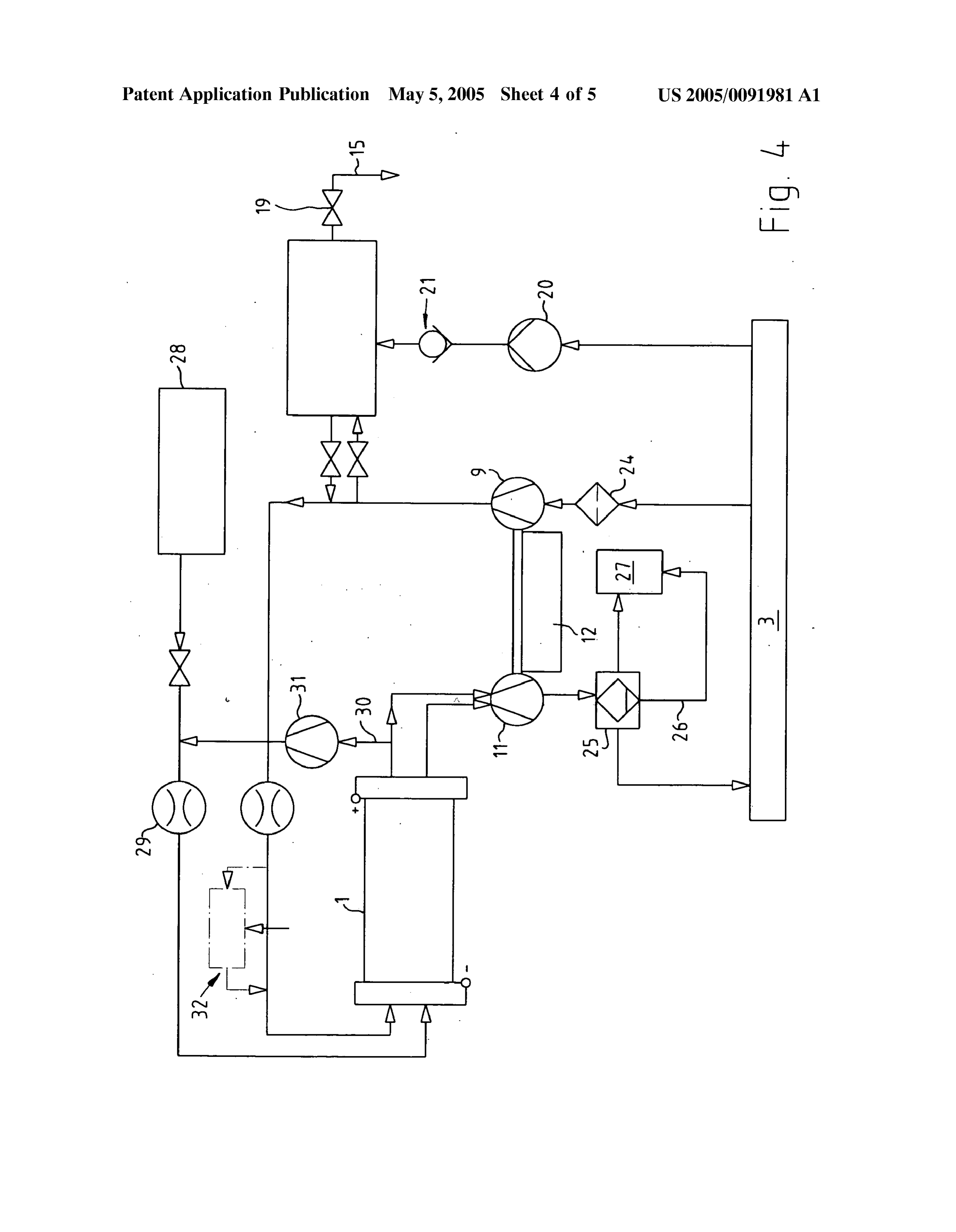
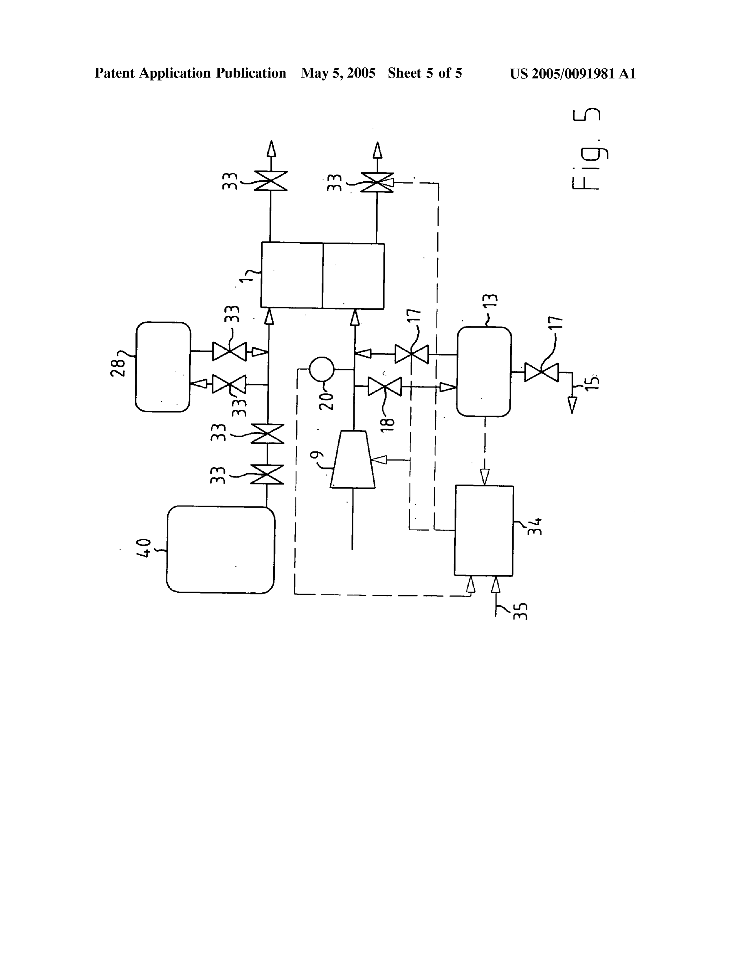
Correspondingly a relatively technically simple or cost BRIEF DESCRIPTION OF THE DRAWINGS favorable pressure generating units for generating the pres
Sure of the compressed air Storage can be also relied on. For 0022 FIG. 1 is a view showing a schematic diagram of example, Standard components can be utilized for this pur a vehicle in accordance with one variant of the present pOSc. invention;
0.017. Furthermore, with the utilization of a separate 0023 FIG. 2 is a view showing a schematic diagram of preSSure generating unit for the compressed air Storage, a a vehicle in accordance with a further inventive variant; reduction of the requirements for the exhaust gas condenser 0024 FIG. 3 is a view showing a schematic diagram of or turbocharger and/or for the compressor or condenser of a vehicle in accordance with a third inventive variant; the fuel cell device can be obtained, which clearly can 0025 FIG. 4 is a view showing a schematic diagram of provide an efficiency optimal design of the total System or the corresponding components. In the prior art, exactly these a vehicle in accordance with an inventive variant, with components, in other words the exhaust gas turbocharger or additional details, and the compressor of the fuel cell unit are designed So that they 0026 FIG. 5 is a view showing a schematic diagram of can also turn over comparitively high load requirements or a vehicle in accordance with a further inventive variant with peak loads. With the advantageous compressed air Storage, other details.
corresponding peak requirements partially can be fulfilled better, So that the design directly of the exhaust gas con DESCRIPTION OF THE PREFERRED denser or the compressor of the fuel cell unit can be EMBODIMENTS developed correspondingly in optimal fashion. This is espe cially true for the impeller design and the work demand of 0027 A fuel cell 1 and a combustion engine 2 are the running gear, Since the requirement for a fast run up time schematically shown in FIG.1. Here only the air path of the can be dispensed with by means of the invention. This leads fuel cell 1 or the motor 2 is shown, while the corresponding both to an increase of the total efficiency as well as to a fuel path is not shown for the sake of clarity. cost-favorable design of the System. 0028. The illustrated components exchange air with the 0.018 Advantageously, a bypass unit to the surrounding Surrounding or environment 3. For example, the motor 2 is of the compressed air Storage is provided. This means that in Supplied with air via an air filter 4 and an exhaust gas general parallel to the compressed air Storage, a bypass or a turbocharger 5 as well as an HFM sensor 8. The air hereby connection conduit is available for connection of the com is distributed or filled by means of a distribution system in bustion engine or its components with the fuel cell or its the combustion chambers of the motor 2. Generally, an HFM components. With this feature for example a Supply of the (Heat Film Air Mass metering) means a system for the combustion engine components via the fuel cell device control of fuel injection and ignition, which is available for components can be realized. Frequently the combustion years. The exhaust gas turbocharger 5 has in particular a engine components have a comparatively high power, So condenser 6 which is driven by a turbine 7, wherein it is that in certain operational or traveling conditions by means operated by the exhaust gas of the motor 2. of the combustion engine compressed air can be advanta 0029. The fuel cell 1 is supplied with air via a compressor geously Supplied to the compressed air Storage and/or the 9 as well as a dosing or a flow rate counter 10. The air which fuel cell unit. On the other hand, by means of the condenser flows out of the fuel cell 1 and is partially converted, is of the fuel cell unit, a charging of air required for the discharged via an expander 11 again to the environment 3.
Page 9
US 2005/009 1981 A1 May 5, 2005
The expander 11 drives the compressor 9 partially with for example for humidifying of the fuel cell unit and/or the Support by an electric drive 12. hydrogen, etc. For this purpose, among others, a humidifier 0.030. A compressed air storage 13 is provided between 32 is provided in particular for humidifying the fuel cell air, the components of the combustion engine 2 and the fuel cell wherein in FIG. 4 it is connected parallel in a bypass. 1. The storage 13 is connected by a conduit 14 or 16 with the 0038 FIG. 4 further shows a hydrogen tank 28, which fuel cell 1 or its components. The conduits 14 or 16 include Supplies the hydrogen via a dosing element 29 to the fuel cell regulating valves 17 or 18. In contrast to the variant shown 1. The partially converted residual gas, which includes a in FIG. 1, also a consolidation of the conduits 14 and 16 residual hydrogen in a certain quantity, is Supplied by means over the valves 17 and 18 with a preferable use of a of return conduit 30 or a hydrogen pump 31 for feeding into correspondingly formed or operating Single valve can be the fuel cell 1.
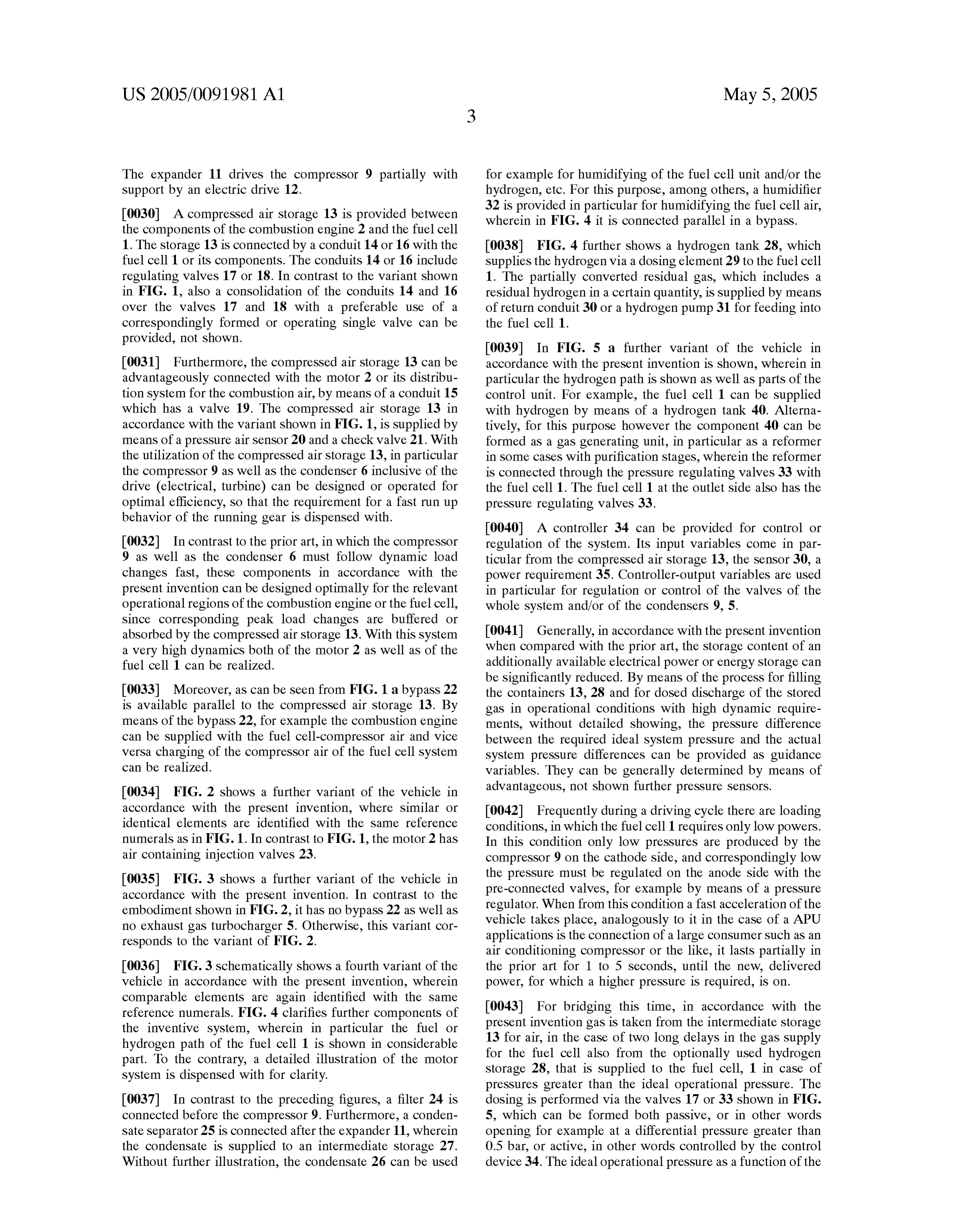
provided, not shown.
0039. In FIG. 5 a further variant of the vehicle in 0.031 Furthermore, the compressed air storage 13 can be accordance with the present invention is shown, wherein in advantageously connected with the motor 2 or its distribu particular the hydrogen path is shown as well as parts of the tion system for the combustion air, by means of a conduit 15 control unit. For example, the fuel cell 1 can be Supplied which has a valve 19. The compressed air storage 13 in with hydrogen by means of a hydrogen tank 40. Alterna accordance with the variant shown in FIG. 1, is supplied by tively, for this purpose however the component 40 can be means of a pressure air sensor 20 and a check valve 21. With formed as a gas generating unit, in particular as a reformer the utilization of the compressed air Storage 13, in particular in Some cases with purification Stages, wherein the reformer the compressor 9 as well as the condenser 6 inclusive of the is connected through the pressure regulating valves 33 with drive (electrical, turbine) can be designed or operated for the fuel cell 1. The fuel cell 1 at the outlet side also has the optimal efficiency, So that the requirement for a fast run up preSSure regulating valves 33.
behavior of the running gear is dispensed with.
0040. A controller 34 can be provided for control or 0032. In contrast to the prior art, in which the compressor regulation of the System. Its input variables come in par 9 as well as the condenser 6 must follow dynamic load ticular from the compressed air Storage 13, the Sensor 30, a changes fast, these components in accordance with the power requirement 35. Controller-output variables are used present invention can be designed optimally for the relevant in particular for regulation or control of the valves of the operational regions of the combustion engine or the fuel cell, whole system and/or of the condensers 9, 5. Since corresponding peak load changes are buffered or absorbed by the compressed air storage 13. With this system 0041 Generally, in accordance with the present invention a very high dynamics both of the motor 2 as well as of the when compared with the prior art, the Storage content of an fuel cell 1 can be realized. additionally available electrical power or energy Storage can be significantly reduced. By means of the process for filling 0.033 Moreover, as can be seen from FIG. 1 a bypass 22 the containers 13, 28 and for dosed discharge of the stored is available parallel to the compressed air Storage 13. By gas in operational conditions with high dynamic require means of the bypass 22, for example the combustion engine ments, without detailed showing, the pressure difference can be Supplied with the fuel cell-compressor air and Vice between the required ideal System pressure and the actual Versa charging of the compressor air of the fuel cell System System pressure differences can be provided as guidance can be realized. variables. They can be generally determined by means of 0034 FIG. 2 shows a further variant of the vehicle in advantageous, not shown further pressure Sensors. accordance with the present invention, where similar or 0042. Frequently during a driving cycle there are loading identical elements are identified with the same reference conditions, in which the fuel cell 1 requires only low powers. numerals as in FIG.1. In contrast to FIG. 1, the motor 2 has In this condition only low pressures are produced by the air containing injection valves 23. compressor 9 on the cathode Side, and correspondingly low 0035 FIG. 3 shows a further variant of the vehicle in the pressure must be regulated on the anode Side with the accordance with the present invention. In contrast to the pre-connected valves, for example by means of a preSSure embodiment shown in FIG. 2, it has no bypass 22 as well as regulator. When from this condition a fast acceleration of the no exhaust gas turbocharger 5. Otherwise, this variant cor vehicle takes place, analogously to it in the case of a APU responds to the variant of FIG. 2. applications is the connection of a large consumer Such as an air conditioning compressor or the like, it lasts partially in 0036 FIG. 3 schematically shows a fourth variant of the the prior art for 1 to 5 seconds, until the new, delivered vehicle in accordance with the present invention, wherein power, for which a higher pressure is required, is on. comparable elements are again identified with the same reference numerals. FIG. 4 clarifies further components of 0043. For bridging this time, in accordance with the the inventive System, wherein in particular the fuel or present invention gas is taken from the intermediate Storage hydrogen path of the fuel cell 1 is shown in considerable 13 for air, in the case of two long delays in the gas Supply part. To the contrary, a detailed illustration of the motor for the fuel cell also from the optionally used hydrogen System is dispensed with for clarity. Storage 28, that is Supplied to the fuel cell, 1 in case of preSSures greater than the ideal operational pressure. The 0037. In contrast to the preceding figures, a filter 24 is dosing is performed via the valves 17 or 33 shown in FIG. connected before the compressor 9. Furthermore, a conden 5, which can be formed both passive, or in other words Sate Separator 25 is connected after the expander 11, wherein opening for example at a differential preSSure greater than the condensate is Supplied to an intermediate Storage 27. 0.5 bar, or active, in other words controlled by the control Without further illustration, the condensate 26 can be used device 34. The ideal operational preSSure as a function of the
Page 10
US 2005/009 1981 A1 May 5, 2005
required power is provided here in the control device 34 by Sors inclusive of drive efficiency can be designed and a curve (p(sys ideal)=f(P(required)). operated optimally, Since the high dynamic requirements are 0044) For filling the storage tank 13, ideally operational fulfilled in advantageous manner by the compressed air conditions are Selected, in which a high pressure is provided Storage 13.
in the System, which for example by releasing a gas pedal 0049. It will be understood that each of the elements Still exit and is to be reduced. The reaction gases under high described above, or two or more together, may also find a preSSure no longer find any use in View of the Significantly useful application in other types of constructions differing lowered performance acceptance. For filing the tanks 13,28, from the types described above.
also passive overpreSSure valves with a return Stroke can be 0050. While the invention has been illustrated and utilized or electrically controlled valves. described as embodied in a vehicle with a combustion 004.5 The pressure reduction in driving situations, in engine and a fuel cell device, it is not intended to be limited which the pressure lies over the ideal operational pressure to the details shown, Since various modifications and struc (p(P required)), must be carried out first via opening of the tural changes may be made without departing in any way valve 18 in FIG. 5 and filling the pressure storage 13. The from the Spirit of the present invention. pressure regulating valve 33 (at an output side of the fuel 0051. Without further analysis, the foregoing will so fully cell) must be controlled in this course differently. When reveal the gist of the present invention that others can, by Ap(=p(Sys actual)-p(Sys ideal) is greater than Zero, then applying current knowledge, readily adapt it for various the valve 18 opens for pressure Storage filling, when Ap is applications without omitting features that, from the Stand Smaller than Zero, for example in case of high Sudden power point of prior art, fairly constitute essential characteristics of requirements the valve 17 opens. When in the first case the the generic or Specific aspects of this invention. preSSure Storage 13 is already filled, the preSSure reduction as before must be performed exclusively by the pressure 0052 What is claimed as new and desired to be protected regulating Valve 33 arranged at an output Side behind the by Letters Patent is set forth in the appended claims. fuel cell 1. In the Second case, a fast pressure buildup in the system can be provided by the buffer effect of the storage 13, 1. A vehicle, comprising a combustion engine; a fuel cell 28 (with knowledge of the level) and accordingly slower and device having a fuel cell unit; a compressed air Storage for thereby efficiency optimal control of the compressor 9. Supply of a compressed air; a Supply conduit provided between said fuel cell unit of Said fuel cell device and said 0046. In certain conditions with this process it is possible, compressed air Storage, for Supplying Said fuel cell unit with with knowledge of the level of the pressure container 13, 28, compressed air; and a further Supply conduit provided to operate the compressor 9, in particular in cooperation with the valves, or the System in favorable efficiency regions, and between Said combustion engine and Said compressed air thereby to reduce the parasitic power consumption of the Storage for Supply of Said combustion engine with com compressor 9. pressed air.
2. A vehicle as defined in claim 1; and further comprising 0047 The use of a hydrogen intermediate storage 28 at least one regulating valve provided for each of Said Supply directly before the fuel cell 1 is offered in particular in the conduits for cooperation with Said compressed air Storage in case, in which for production of the hydrogen reforming or a manner Selected from the group consisting of filling, gas purifying Stages are connected in Series. The time emptying, and both of Said compressed air Storage. constants for the hydrogen Supply with conventional pro 3. A vehicle as defined in claim 1; and further comprising ceSSes lasts with a load jump without the Storage 28 fre at least one regulatable pressure generating unit for produc quently more than 10 Seconds, which makes necessary a ing the compressed air and for filling Said compressed air buffering by means of the storage 28. Storage.
0.048 Basically, the important advantages of the inven 4. A vehicle as defined in claim 3, wherein Said pressure tion reside in the multiple use of the pressure System for the generating unit is formed as an exhaust gas condenser of Said fuel cell 1 and the motor drive 2, with minimal modification combustion motor.
expenses of conventional individual components. The com 5. A vehicle as defined in claim 3, wherein said pressure pressed air Storage 13 fed in Stationary vehicle operating generating unit is formed as a condenser of Said fuel cell points by the compressed air pump, So that particularly high device.
dynamic requirements for the electrical condenser drives, 6. A vehicle as defined in claim 1; and further comprising for example injection valves, connected with corresponding a bypass unit for bypassing Said compressed air Storage. on-board and energy Storage load are dispensed with. In 7. A vehicle as defined in claim 1; and further comprising particular, this pressure Storage unit 13 can be utilized with a pressure generating unit of Said fuel cell unit, which is corresponding design for the Simultaneous dynamic opera formed for Supplying Said combustion engine during a tion of a turbo-charged combustion engine 2 and a PEM fuel dynamic operation.
cells-auxiliary power unit, for example for the So-called
Clean Energy Concept vehicle. Furthermore, the compres
Provenance
- Collection
- Patents citing this work
- Current assignee
- Robert Bosch GmbH
- Pages
- 10
- Method
- pdftotext (the PDF's own text layer) + pdftoppm 300dpi page scans
- Patent office record
- patents.google.com →
- Source
- Google Patents citing-documents table
- Inventors
- Rainer Saliger; Thomas Heid; Markus Koberstaedt
- Published
- 2005-05-05
- Transcribed from
- patentimages.storage.googleapis.com →