patent · US10066990
Spatially variable filter systems and methods
4 September 2018
Page 1 — bibliographic record
(12) United States Patent ( 10) Patent No.: US 10 , 066 ,990 B2 Rosen et al. (45) Date of Patent: Sep . 4 , 2018 (54) SPATIALLY VARIABLE FILTER SYSTEMS (56 ) References Cited AND METHODS U .S . PATENT DOCUMENTS (71) Applicant: VERIFOOD, Ltd ., Herzliya (IL ) 679 ,577 A 7 / 1901 Schaffner
(72 ) Inventors: Sagee Rosen , Netzer Sireni (IL ); Uri (Continued ) Kinrot, Hod HaSharon ( IL ) (73) Assignee : VERIFOOD , LTD ., Herzliya (IL ) FOREIGN PATENT DOCUMENTS
( * ) Notice : Subject to any disclaimer, the term of this CN 101501465 A 8 / 2009 patent is extended or adjusted under 35 (Continued )
( 21 ) Appl. No.: 15 / 191,031 OTHER PUBLICATIONS Acktar Advanced Coatings Website . Accessed Jun . 3 , 2015 . http :// (22 ) Filed : Jun . 23 , 2016 www .acktar.com /
(Continued ) (65) Prior Publication Data Primary Examiner — Dominic J Bologna US 2017 /0010160 A1 Jan . 12, 2017 (74 ) Attorney, Agent, or Firm — Wilson , Sonsini, Goodrich & Rosati
Related U .S . Application Data (57 ) ABSTRACT
An improved compact spectrometer system comprising an (60 ) Provisional application No. 62 /190 ,544, filed on Jul. improved spatially variable filter is disclosed herein . A 9 , 2015 . spatially variable filter may be configured to have a plurality of different transmission profiles at different locations of the (51) Int . Ci. filter, to spectrally separate light incident on the filter . The GO1J 3 /51 (2006 . 01) spatially variable filter may comprise a plurality of different GO1J 3/02 ( 2006 .01) filter regions having different transmission profiles , and a ( Continued ) plurality of similar filter regions comprising similar trans (52 ) U .S . CI. mission profiles. The spatially variable filter may be opti
GORJ 3 /0256 (2013 .01 ); G01J 3/ 26 cally coupled to a detector comprising a plurality of detector ( 2013 . 01) ; G01J 3 /2803 (2013 . 01 ) ; GO1J 3 /36 elements configured to measure the intensity of light. The (2013.01 ); GOIJ 2003 /2806 (2013.01 ) measurement data generated by the plurality of detector (58 ) Field of Classification Search elements coupled to the plurality of similar filter regions can CPC ... GO1J 3/0256 ; G01J 3/36 ; G01J 3/26 ; G01J be used to determine a spatial variation on incident light
See application file for complete search history. 19 Claims, 10 Drawing Sheets
..waww
UTALDRAW
Page 2
(51) Int. CI. 8 , 269, 174 B2 9/ 2012 Gardner, Jr. et al. GO1J 3 / 26 (2006 .01) 8,274 , 739 B2 9 /2012 Lee et al. GO1J 3 /28 (2006 .01) 8 ,284,401 B2 10 /2012 Choi et al.
GO1J 3 / 36 ( 2006 .01) 8,462 ,420 B2 6 / 2013 Lee et al.
( 56 ) References Cited 8,526, 002 B2 9 /2013 Deflores et al.
U . S . PATENT DOCUMENTS 8,593,628 B2 . 11/ 2013 Shimbo et al.
4 ,884 ,860 A 12 / 1989 Brown 8,654 ,327 B2 2 /2014 Bohle et al. 5 ,059,795 A 10 / 1991 Izumi 8,665 ,440 B1 3 /2014 Kompaniets et al. 5 , 159 ,199 A * 10 / 1992 LaBaw GO1J 3 /02 8,675 ,188 B2 3 /2014 Liu et al. 250/ 339 .02 8, 711 ,360 B2 4 / 2014 Funamoto 5 , 469 ,252 A 11/ 1995 Doles et al. 8, 711 ,362 B2 4 / 2014 Funamoto 5 , 966 ,212 A 10 / 1999 Hendler et al. 8 , 735, 820 B2 5 /2014 Mertens 6 ,031,233 A 2 / 2000 Levin et al. 8,742,320 B2 6 / 2014 Shibayama et al. 6 ,031,619 A 2 / 2000 Wilkens et al. 8,760 , 645 B2 6 / 2014 Misener et al. 6 ,069,696 A 5 /2000 McQueen et al. 8 , 773, 659 B2 7 / 2014 McClure 6 ,072 ,576 A 6 / 2000 McDonald et al. 8 , 786, 854 B2 7 /2014 Miyazono 6 ,212,312 B1 . 4 / 2001 Grann et al. 8 , 848, 187 B2 9 / 2014 Uematsu et al.
6 , 323, 944 B1 * 11/ 2001 Xiao ..... GO1J 3 /02 8 ,867 ,033 B2 10 /2014 Carron et al . 250 / 458 . 1 8 , 868 ,387 B2 10 /2014 Den et al .
6 ,333, 501 B1 12 / 2001 Labrenz 8,873 , 046 B2 10 /2014 Miyazono 6 ,441,375 B1 8 / 2002 Joseph et al. 8 ,937,717 B21 / 2015 Preston et al. 6 ,456 ,373 B19 / 2002 Wienecke et al. 8 ,976,357 B2 3/ 2015 Uematsu et al. 6 ,483,583 B1 11/ 2002 Wright et al. 9 , 030 , 662 B2 5 / 2015 Lee et al. 6 ,615, 142 B1 9 /2003 Hovde 9 , 060,113 B2 6 /2015 Rhoads et al. 6, 639, 666 B2 10/ 2003 Li 9 , 063, 011 B2 6 /2015 Chen et al. 6 ,700 ,661 B13 / 2004 Cadell et al. 9 , 074 ,933 B2 7 / 2015 Yokino et al. 6 ,717 ,669 B2 4 / 2004 Ruiz 9 , 128, 055 B2 9 / 2015 Sekino et al. 6 ,836 ,325 B2 12 /2004 Maczura et al . 9,163, 986 B2 10 /2015 Bouckaert 6 , 864, 978 B1 . 3 /2005 Hazen et al. 9,173 , 508 B2 11 /2015 Tornwall et al. 6 ,958,479 B2 10 /2005 Burling- Claridge et al. 9 , 182 ,280 B1 11/ 2015 Gardner et al. 7 ,009, 702 B2 3 / 2006 Caruso et al. 9 , 234 ,800 B2 1/2016 Kawamata et al. 7 ,038, 774 B2 5 / 2006 Hazen et al. 9, 239 , 264 B1 1/2016 Demers 7 ,068,366 B2 6 / 2006 Burk et al. D750 ,988 S 3 /2016 Goldring 7 ,075 , 643 B2 7 / 2006 Holub D751,435 S 3 /2016 Goldring 7 ,084 ,974 B1 8 /2006 Barwicz et al. 9 , 291, 504 B2 3 / 2016 Goldring et al. 7 ,145,650 B2 12 / 2006 Wang et al. 9, 297 , 821 B2 3 /2016 Walter et al. 7 ,151,600 B2 12/2006 Imura 9,301, 626 B2 4 /2016 Tornwall et al. 7 , 158, 225 B2 1/ 2007 Tedesco et al. 9 ,310, 564 B2 4 / 2016 Martinelli et al. 7 ,235 , 766 B2 6 / 2007 Shur et al. 9 , 377, 396 B2 6 /2016 Goldring et al. 7 ,236,243 B2 6 / 2007 Beecroft et al. 9 , 383, 258 B2 7 /2016 Goldring et al. 7 , 245,372 B2 7 /2007 Han 9 ,383,308 B2 7 /2016 Bradley et al. 7 ,248,370 B2 7 /2007 Jones 9, 395 , 244 B2 7 / 2016 Kurokawa et al. 7 ,251, 037 B2 7 / 2007 Jones 9,417, 180 B2 8 /2016 Seo et al. 7 ,262 , 839 B2 8 / 2007 Treado et al . 9 , 448 ,114 B2 9 /2016 Goldring et al . 7 ,286, 233 B2 10 /2007 Pizzi 9, 448,165 B2 9 /2016 Gulati et al. 7, 339,665 B2 3 / 2008 Imura 9 , 453 ,794 B2 9 /2016 Gulati et al. 7, 414,724 B2 8/ 2008 Eckert et al. 9 ,464, 934 B2 10 /2016 Priore et al . 7 ,420, 663 B2 9 /2008 Wang et al. 9 ,488 ,468 B2 11/2016 Tsujii et al. 7,426 ,446 B2 9 / 2008 Hagler 9 ,488 ,523 B2 11/2016 Yokino et al. 7 ,433, 042 B1 10 / 2008 Cavanaugh et al. 9 ,500 ,523 B2 11/ 2016 Goldring et al. 7 ,436 ,511 B2 10 / 2008 Ruchti et al. 9 ,508 ,765 B2 11/2016 Owa et al. 7 ,489 ,396 B1 2/ 2009 Vrhel et al. 9 ,518 ,917 B2 12 /2016 Scherer et al. 7 ,528,957 B2 5 / 2009 Lewis et al. 9 , 546,902 B2 1/ 2017 Kovacich et al. 7 ,535, 617 B2 5 /2009 Gupta et al . 9 , 546,904 B2 1/2017 Pawluczyk et al. 7 ,649,627 B2 1/ 2010 Yamamoto 9 , 557,220 B2 1 /2017 Yasui et al. 7 ,667,740 B2 2/ 2010 Hofer 9 ,562, 848 B2 2 /2017 Goldring et al. 7 ,697, 136 B2 4 / 2010 Imura 9 ,568 ,363 B2 2 / 2017 Yu et al. 7, 767 ,969 B2 8 / 2010 Nagai et al. 9 , 574, 942 B2 2/2017 Goldring et al. 7 , 805,319 B2 9 / 2010 Badinelli 9, 587,982 B2 3/2017 Goldring et al. 7 ,817 , 273 B2 10 / 2010 Bahatt et al. 2001/0009972 A1 7 /2001 Doi et al. 7, 868, 296 B2 1 /2011 Haran et al . 2002/0039186 A1 4 / 2002 Rosenberg et al. 7 ,876,435 B2 1 / 2011 Becker -Ross et al. 2002 /0131047 A1 9 /2002 Zarrabian et al. 7 ,881 ,892 B2 2 /2011 Soyemi et al. 2002/0145728 A1 10 /2002 Adams et al. 7 ,897,923 B2 3 /2011 Shelley et al. 2002 /0154315 A1 * 10 /2002 Myrick .. GO1J 3 / 18 7 , 907 ,282 B2 3 /2011 Coates 356 /305
8 ,125, 633 B2 2 / 2012 Whelan et al . 2003/0122080 A1 7 /2003 Burling-Claridge et al. 8 , 144, 322 B2 3 / 2012 Nagashima et al . 2004 /0019462 AL 1 /2004 Gehrlein et al. 8 , 149, 415 B2 4 /2012 Sanders et al. 2004 /0136577 Al 7 /2004 Rao et al. 8 ,169, 607 B2 5 / 2012 Sano et al. 2004 /0213459 A1 10 /2004 Ishimaru et al. 8 ,169 , 608 B2 5 / 2012 Sano et al. 2005 /0117151 Al 6 /2005 Han 8 , 247, 774 B2 8 / 2012 Chou et al. 2005 /0128477 Al 6 / 2005 Caruso et al.
Page 3
( 56 ) References Cited 2014 /0320858 A1 10 /2014 Goldring et al.
U . S . PATENT DOCUMENTS 2015 / 0036138 A1 2 /2015 Watson et al .
2005 /0149598 A1 7 /2005 Mendlovic et al. 2015 / 0062577 Al 3 /2015 Hartwell et al. 2005 /0151975 A1 7/ 2005 Melnyk 2015 /0103354 Al 4 / 2015 Saptari et al. 2005/0196046 AL 9 / 2005 Hudnut et al. 2015 /0108333 A1 4 / 2015 Bouckaert 2006 /0086901 A1 4 / 2006 Price et al. 2015 /0116707 A1 4 / 2015 Tatsuda 2006 /0124656 AL 6 / 2006 Popovich , Jr. et al. 2015 /0119661 A1 4 / 2015 Gilbert et al . 2006 /0132760 A1 6 / 2006 Imura 2015 /0153225 A1 6 / 2015 Baudelet 2006 /0146315 AL 7 / 2006 Treado 2015 / 0204833 A1 7 / 2015 O 'Brien et al. 2006 /0279732 Al 12 / 2006 Wang et al. 2015 / 0260573 A1 * 9/ 2015 Ishimaru ........... GO1J 3/4532 2006 /0280096 Al 12/2006 Riley et al. 356 / 451 2007 /0145273 AL 6 / 2007 Chang 2015 / 0292948 A1 10 / 2015 Goldring et al. 2007/ 0230932 Al 10/ 2007 Tanaka et al. 2015 /0300879 Al 10 /2015 Goldring et al. 2007 /0290284 A1 * 12 / 2007 Shaffer . . . HOUL 27 / 1446 2015 /0323383 Al 11/ 2015 Pastore et al.
2008 /0061236 Al 3 /2008 Meredith et al. 2016 /0018260 A1 1 /2016 Samuels 2008 /0073510 Al 3 / 2008 Finlay 2016 /0033328 A1 2 /2016 Walters 2008/0112853 A1 5 / 2008 Hall 2016 /0091369 Al 3 / 2016 Sakurai et al. 2008/0137328 A1 6 / 2008 Lee et al. 2016 /0103069 Al 4 /2016 Umapathy et al. 2008/0151241 A1 6 / 2008 Lindfors et al. 2016 /0223400 A1 8 / 2016 Carron et al. 2008/0204578 A1 8 / 2008 Scheuch et al. 2016 /0231171 Al 8 / 2016 Assefa et al. 2008 /0265146 AL 10 /2008 Coates 2016 /0245700 A1 8 /2016 Uematsu et al. 2008 /0277625 AL 11/ 2008 Nakamura et al. 2016 /0258813 A1 9 /2016 Kuri 2008 /0297379 Al 12 / 2008 Yang et al. 2016 /0263910 A1 9 /2016 Kanai et al. 2008/0297791 Al 12/ 2008 Imura 2016 /0282182 A1 9 / 2016 Kanai et al. 2009 /0051910 A1 2 /2009 Imura 2016 /0290863 A 10 /2016 Goldring et al. 2009 /0201577 A1 8/ 2009 Laplante et al . 2016 /0299004 AL 10 /2016 Thamm 2009 /0213361 Al 8 / 2009 Vander et al. 2016 / 0299061 A1 10 / 2016 Goldring et al. 2009 /0294637 A1 12 / 2009 Kusano et al. 2016 /0305820 Al 10 /2016 Zollars et al. 2010 /0078564 A 4 /2010 McAllister et al. 2016 / 0313184 Al 10 / 2016 Owechko 2010 /0080351 A1 4 / 2010 Hession -Kunz et al. 2016 /0334274 A1 11/ 2016 Xu 2010 /0085537 A1 4 / 2010 Ramella -Roman et al. 2016 /0356646 A112/ 2016 Wiegand et al. 2010 /0110442 Al 5 /2010 Adibi et al. 2016 /0356647 Al 12/2016 Wiegand et al. 2010 /0128370 A1 5 / 2010 Chen et al. 2016 /0356704 Al 12/2016 Kim et al. 2010 /0134794 Al 6 / 2010 Odegard et al. 2017/0003167 A11 /2017 Ave 2010 /0165337 AL 7 / 2010 Dirk 2017 /0027447 A1 2/ 2017 Sutin et al. 2010 /0191493 Al 7 / 2010 Brown et al. 2017 / 0038257 Al 2 / 2017 Liu et al. 2010 /0201979 A 8 / 2010 Momtahan et al. 2017 /0153142 A16 /2017 Rosen et al. 2010 /0271352 Al 10 / 2010 Nakano et al. 2017 /0160131 A1 6 /2017 Goldring et al. 2010 /0284005 AL 11/ 2010 Malinen et al. 2017 /0234729 A1 8/2017 Goldring et al. 2010/0292581 A111/ 2010 Howard et al. 2017 /0254701 Al 9 /2017 Goldring et al. 2010 / 0309454 Al 12 / 2010 Zhang 2018/0003558 A1 1/2018 Goldring et al.
2011/0082449 A14 /2011 Melsky et al. FOREIGN PATENT DOCUMENTS 2011/0215432 A1 * 9 / 2011 Uematsu ........ ... A61B 5 /14552
2011/0255745 Al 10 / 2011 Hodder et al. 2001236583 A 8 /2001 2011 /0261252 Al 10 / 2011 Chen 2002277326 A 9 / 2002 2011/0299104 A1 * 12 / 2011 Seo GO1J 3 /02 2004294361 A 10 /2004
2011/ 0318717 Al 12/2011 Adamowicz 2007218878 A 8 /2007 2012 /0001083 A11 /2012 Knapp 2008286522 A 11/ 2008 2012 / 0018829 Al 1/ 2012 Beck et al. 2009104547 A 5 /2009 2012 /0019819 AL 1/ 2012 Messerchmidt 2011198801 A 10 /2011 2012 /0053426 AL 3 / 2012 Webster et al. WO WO - 9953350 A1 10 /1999 2012 /0088486 AL 4 / 2012 Messerchmidt WO WO - 2010027982 A2
2012 / 0099102 A1 4 / 2012 Bello WO 4 / 2010 2012 /0286046 AL 11/ 2012 Ciurczak et al. WO WO - 2013065035 A1 5 /2013 2012 /0327248 A1 * 12 / 2012 Tack GO1J 3 /26 WO WO - 2013082272 A1 6 /2013
2013/0021611 AL 1/ 2013 Tsurutani WO WO -2013148461 A1 10 /2013 2013 /0107260 A15 / 2013 Nozawa WO WO - 2013150290 A1 10 / 2013 2013 /0155402 A1 6 /2013 Walton et al . wo WO - 2013162850 A 10 /2013 2013 /0182250 AL 7 / 2013 McClure WO WO - 2013163268 A1 10 /2013 2013 /0258341 Al 10 / 2013 Day et al. WO WO -2013165887 AL 11/2013 2014 /0002817 A11 / 2014 Ross et al. WO WO - 2014014534 A2 1/2014 2014 /0029004 A1 * 1/2014 Bodkin ... G01J 3 /02 WO WO - 2014033783 A1 3 / 2014
2014 /0046630 A1 2 / 2014 Smith et al. WO WO -2014064447 Al 5 / 2014 2014 / 0052555 A1 2 / 2014 MacIntosh WO WO - 2014102629 Al 7 /2014 2014 /0061486 A1 3 / 2014 Bao et al . WO WO - 2014129305 Al 8 / 2014 2014 / 0064479 Al 3/ 2014 Manikandan et al. WO WO -2014139003 A1 9 / 2014
2014 /0192255 A1 * 7/ 2014 Shroff .................... GOIN 21/ 27
348 / 362 Wo WO -2015015493 A3 3 /2015 2014 /0293091 Al 10 /2014 Rhoads et al. WO WO - 2015038372 A1 3 /2015
Page 4
( 56 ) References Cited Co -pending U . S . Appl. No . 15 / 482 ,546 , filed Apr. 7 , 2017 . Co -pending U .S . Appl. No. 15 /493,006 , filed Apr. 20 , 2017 .
FOREIGN PATENT DOCUMENTS Co -pending U . S . Appl. No. 15 /660,573, filed Jul. 26 , 2017 . Co -pending U .S . Appl. No . 15 /667,360 , filed Aug . 2 , 2017 .
WO WO - 2015042617 A1 3 / 2015 Co -pending U .S . Appl. No. 15 /667,489 , filed Aug. 2 , 2017 .
Co -pending U .S . Appl. No. 15 /713 , 198 , filed Sep . 22 , 2017 .
WO WO - 2015101992 A2 7 / 2015 Co -pending U .S . Appl. No. 15 /727 ,291, filed Nov . 16 , 2017 . WO WO - 2015101992 A3 9 /2015 Co-pending U .S . Appl. No. 15 /796 ,290 , filed Oct. 27 , 2017. WO WO - 2015138028 A2 9 /2015 European search report and search opinion dated Feb . 7 , 2017 for WO WO - 2015138028 A3 11 / 2015 EP Application No. 14831451. 1.
WO WO -2016022283 A1 2 / 2016 European search report and search opinion dated Jul. 24 , 2015 for WO WO - 2016033224 Al 3 /2016 EP Application No. 12845773 .6 .
WO WO - 2016059946 A1 4 / 2016 European search report and search opinion dated Aug . 7 , 2017 for
WO WO - 2016124659 Al 8 /2016 EP Application No. 15733267.7 .
WO WO - 2016125165 A2 8 / 2016 Interference Filter Handbook , published by JDS Uniphase (Second WO WO - 2016125165 A3 12 /2016 Edition ), Sep . 2006 , p . 195 - 202 and 213 - 214 . WO WO - 2016196727 A2 12 / 2016 International search report and written opinion dated Jan . 26 , 2015 W0 WO - 2016196727 A3 1/ 2017 for PCT Application No. IL2014/050688. International search report and written opinion dated Mar. 22, 2013
OTHER PUBLICATIONS for PCT Application No. IL2012 /000367 .
International search report and written opinion dated Jul. 14 , 2015
Anoplate Website. Accessed Jun . 3 , 2015. http://www .anoplate . for PCT Application No. PCT /IL2015 /050002. com / capabilities/ anoblack _ ni.html. International search report and written opinion dated Aug . 25 , 2016 Avian Technologies Website . Accessed Jun . 3 , 2015 . http ://www . for PCT Application No . PCT /IL2016 / 050130 . aviantechnologies .com /products / coatings/ diffuse _ black .php .
Co -pending U .S . Appl. No. 15 /479 , 105 , filed Apr. 4 , 2017 . * cited by examiner
Page 5
Drawing sheet — no readable text.
Page 6
Drawing sheet — no readable text.
Page 7
Drawing sheet — no readable text.
Page 8
U . S . Patent Sep . 4 , 2018 Sheet 4 of 10 US 10 , 066 , 990 B2
manenoyangu gangguan
wwwwwwwwwwwwwwwwww wwwwwww
mmmmmmmmmmmmmmy
FIG . 5A
ÜRIT
W yryyyyyyyy
h thystytty tyytyttyythe
FIG . 5B
retty tyytytytytyttyy yhteytty tyyty
Page 9
U . S . Patent Sep . 4 , 2018 Sheet 5 of 10 US 10 , 066 , 990 B2
AWN
VELY
TIILIVYOIY
. 340b
645 635 655 620 A 625 de los esta tarde
Haddadded
r te laten Parma
340d 340 300
FIG . 6A
Page 10
Drawing sheet — no readable text.
Page 11
Drawing sheet — no readable text.
Page 12
U . S . Patent Sep . 4 , 2018 Sheet 8 of 10 US 10 , 066 , 990 B2
Measure intensity of light detected by exposed pixels
Measure intensity of light detected by covered pixels
Determine spatial variation of light intensity ?????????????????????????????????????????????????????????????????????? * ttttttttttttttttttttttttttttttttttttttttttttttttttttttttttttttttttt
Adjustmeasurements made by covered pixels to reduce spatial variation of light intensity
Generate adjusted spectra based on adjusted measurement data
Page 13
U . S . Patent Sep . 4 , 2018 Sheet 9 of 10 US 10 ,066 ,990 B2
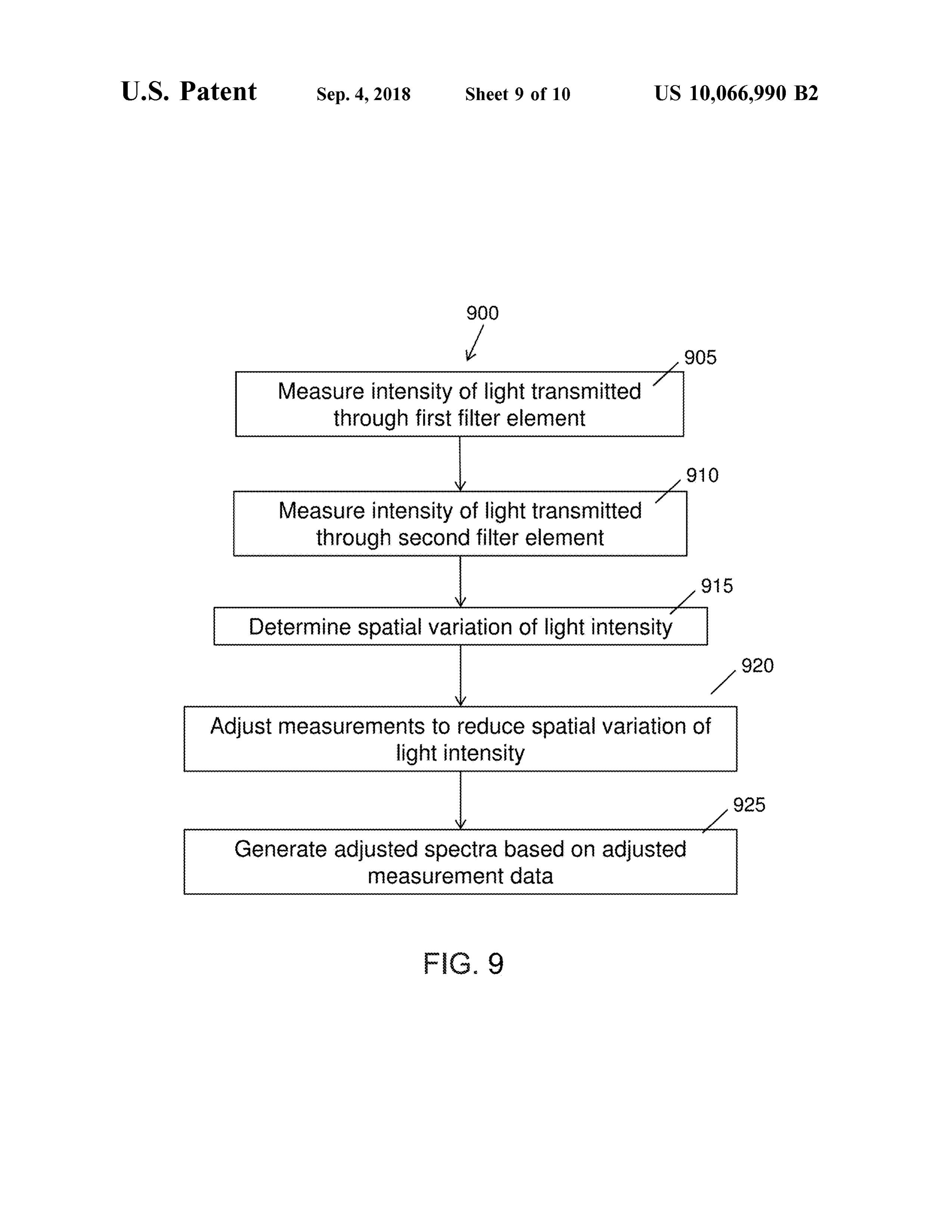
Measure intensity of light transmitted ' through first filter element
Measure intensity of light transmitted through second filter element
Determine spatial variation of light intensity
Adjustmeasurements to reduce spatial variation of light intensity
Generate adjusted spectra based on adjusted measurement data
FIGpo o . 9
Page 14
U . S . Patent Sep . 4 , 2018 Sheet 10 of 10 US 10 ,066 ,990 B2
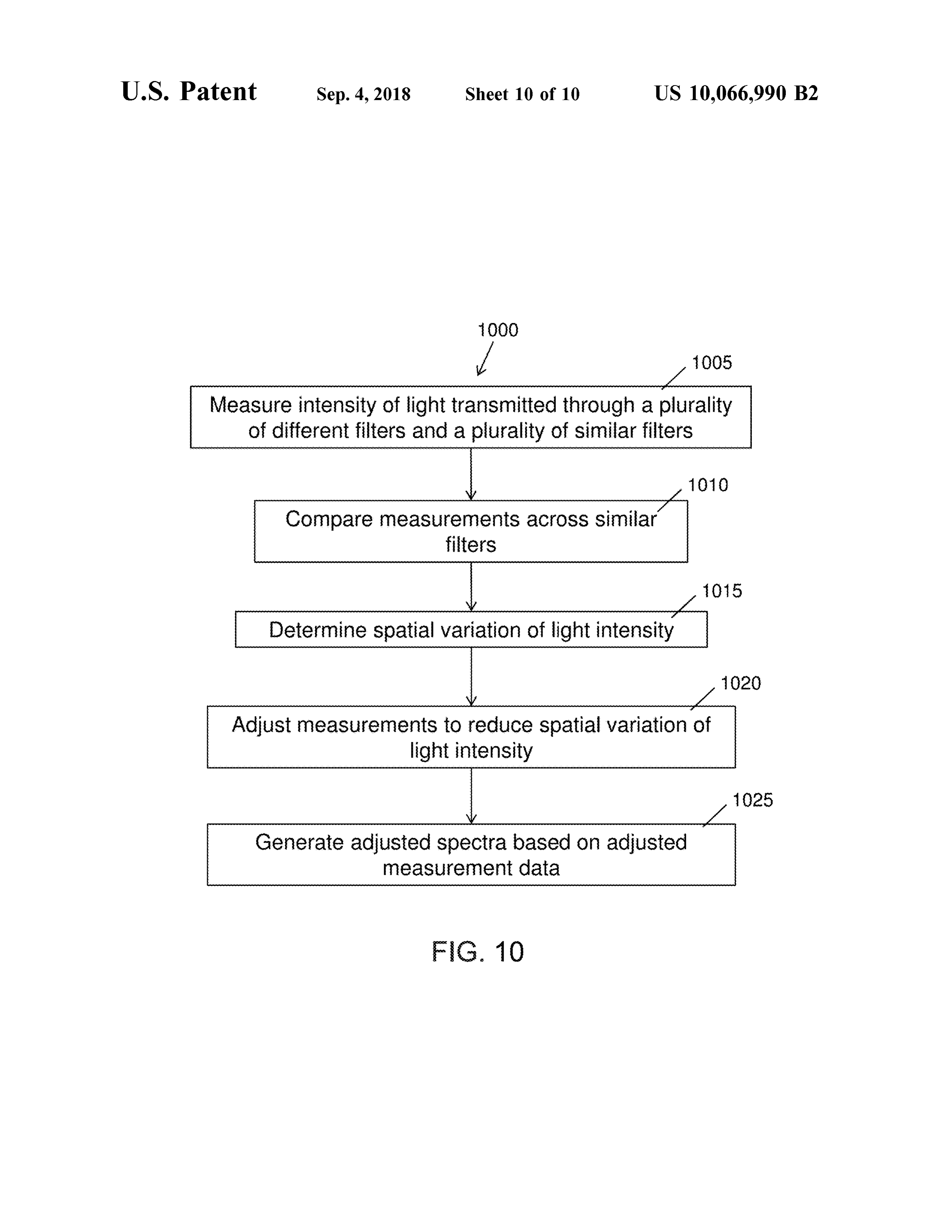
Measure intensity of light transmitted through a plurality of different filters and a plurality of similar filters
Compare measurements across similar filters
Determine spatial variation of light intensity
Adjustmeasurements to reduce spatial variation of light intensity
Generate adjusted spectra based on adjusted measurement data
Page 15
SPATIALLY VARIABLE FILTER SYSTEMS filters can introduce distortions into the output spectrum of AND METHODS the incident light. Such distortionsmay be attributable to , for example, changes in the position and / or orientation of the
CROSS -REFERENCE spectrometer 's input window with respect to the sample 5 plane . Therefore , prior spatially variable filters may be less
The present application claims the benefit of U . S . Provi- than ideally suited for use with compact spectrometers, sional Patent Application No. 62 / 190 ,544 , filed on Jul. 9, which ideally can measure samples at various positions and 2015 , the entire contents of which are incorporated herein by orientations with respect to the spectrometer 's input win reference . dow .
The subject matter of the present application is also 10 In light of the above , improved spatially variable filters related to U . S . patent application Ser . No . 14 /356 , 144 , now and compact spectrometers would be beneficial. Ideally , U . S . Pat. No . 9 ,377, 396 , filed May 2 , 2014 , entitled “ Low such improved spatially variable filters and compact spec Cost Spectrometry System for End -User Food Analysis ” , trometers would reduce distortions of the output spectrum U .S . patent application Ser. No. 14 /702, 342, now U .S . Pat due to variations in incident light intensity across the area of No. 9,291,504, filed on May 1, 2015 , entitled “ Spectrometry 15 the filter.
System with Decreased Light Path " , PCT Application PCT/
IL 2015/ 050002 , filed on Jan . 1, 2015 , entitled “ Spectro SUMMARY OF THE INVENTION scopic Devices and Systems”, PCT Application PCT/
IL2015 /051040 , filed on Oct. 22 , 2015 , entitled An improved compact spectrometer system comprising “ Accessories for Handheld Spectrometer” . PCT Application 20 an improved spatially variable filter is disclosed herein . The PCT/IL2016 /050130 , filed on Feb . 4 , 2016 , entitled “ Spec - spectrometer comprises a spatially variable filter in order to trometry System with Visible Aiming Beam ” , and PCT adjust output spectral data in response to spatial variations of Application PCT/IL2016 /050362, entitled “ Detector for light energy incident on the filter. The spatially variable filter Spectrometry System ” , each of which is incorporated herein may comprise a plurality of spaced apart filter regions by reference in its entirety . 25 having similar transmission profiles in order to measure spatial variation of the input light energy incident on the
INCORPORATION BY REFERENCE spatially variable filter. Themeasured spatial variation of the input light energy can be used to adjust output spectral data
All publications, patents, and patent applications men - in order to reduce distortion of the output spectral data tioned in this specification are herein incorporated by ref- 30 related to the spatial variation in intensity of the light energy erence to the same extent as if each individual publication , incident on the spatially variable filter. patent, or patent application was specifically and individu The spatially variable filter may be configured with a ally indicated to be incorporated by reference . plurality of different transmission profiles at different loca tions of the filter, to spectrally separate light incident on the
BACKGROUND OF THE INVENTION 35 filter . The spatially variable filtermay comprise one or more linear variable filters , discrete filters , or combinations
Spectrometers are used for many purposes. For example , thereof. The spatially variable filter may comprise a plurality spectrometers are used in the detection of defects in indus - of different filters having different transmission profiles . trial processes , satellite imaging, and laboratory research . Each of the different filters may comprise a plurality of However, these instruments have typically been too large 40 similar filters at a plurality of locations of the spatially and too costly for the consumer market . variable filter, the similar filters having similar transmission Spectrometers detect radiation from a sample and process profiles .
the resulting signal to obtain and present information about The spatially variable filter may be optically coupled to a the sample that includes spectral, physical and chemical detector comprising a plurality of detector elements such as information about the sample . These instruments generally 45 pixels , each pixel configured to measure an intensity of include some type of spectrally selective element to separate incident light that has been spectrally separated by the wavelengths of radiation received from the sample, and a spatially variable filter. The spatially variable filter and the first- stage optic , such as a lens, to focus or concentrate the detector can be configured to generate measurement data radiation onto an imaging array. indicative of the spatial distribution of the incident light. The Prior spectrometers and filters , such as linear variable 50 spatial distribution of the incident light can then be used to filters , can be used as wavelength separating elements for adjust the measurement data of the spectrally separated compact spectrometers. A linear variable filter can be gen - incident light. A processormay be operatively coupled to the erally configured to have a plurality of transmission profiles , detector, wherein the processor comprises instructions to that vary across a length of the filter. Collimated light adjust the measurement data based on intensity variations in incident on the linearly variable filter may be spectrally 55 the incident light. The spatially variable filter system can separated by the filter, based on the location at which the generate adjusted spectra with reduced distortions resulting incident light hits the filter. A detector optically coupled to from non - uniform light distribution on the filter. the filter can detect the intensity of incident light at different In one aspect, a spectrometer comprises a spatially vari wavelengths. The prior spectrometers and spatially variable able filter , a detector, and a processor, wherein the spatially filters can be subjected to incident light having a non - 60 variable filter comprises a first plurality of similar spaced uniform intensity distribution across the area of the filter . apart regions having similar transmission profiles and a Such spatial variation of the incident light intensity can second plurality of different spaced apart regions having produce distortions in the spectral representation of the different transmission profiles . The detector comprises a measured sample . plurality of detector elements coupled to the spatially vari The prior spatially variable filters for separation of inci- 65 able filter. The processor is configured with instructions to dent light can be less than ideally suited for use with receive data from the detector and output spectral data to compact spectrometers. For example , prior linear variable determine a spectrum in response to transmitted light inten
Page 16
sity at the plurality of similar spaced apart regions and the FIG . 8 is a flow chart illustrating a method of reducing plurality of different spaced apart regions. measured intensity variations across an area of a linear In another aspect , a spatially variable filter comprises a variable filter as shown in FIG . 4 ; plurality of different filter regions comprising different trans- FIG . 9 is a flow chart illustrating a method of reducing mission profiles at a plurality of locations of the spatially 5 measured intensity variations across an area of a linear variable filter to spectrally separate light incident on the variable filter as shown in FIGS. 5A and 5B ; and filter. At least one of the different transmission profiles is FIG . 10 is a flow chart illustrating a method of reducing repeated at a plurality of spaced apart regions of the spatially measured intensity variations across an area of a linear variable filter. variable filter as shown in FIG . 6A . In another aspect, a spectrometer system comprises a spatially variable filter having a plurality of different trans DETAILED DESCRIPTION OF THE mission profiles , wherein at least one of the plurality of INVENTION different transmission profiles is repeated at two or more In the following description , various aspects of the inven spaced apart regions of the spatially variable filter. The 15 tion will be described . For the purposes of explanation . spectrometer system further comprises a detector optically specific details are set forth in order to provide a thorough coupled to the spatially variable filter , and a processor understanding of the invention . It will be apparent to one coupled to the detector. The processor is configured to skilled in the art that there are other embodiments of the measure transmitted light intensity at the plurality of non - invention that differ in details without affecting the essential adjacent locations of the spatially variable filter in order to 20 nature thereof. Therefore the invention is not limited by that adjust output spectra in response to intensity variations which is illustrated in the figure and described in the among the plurality of similar filters at the plurality of specification , but only as indicated in the accompanying non -adjacent locations . claims, with the proper scope determined only by the In another aspect, a method of measuring spectra com - broadest interpretation of said claims.
prises measuring an intensity of light incident on each of a 25 A better understanding of the features and advantages of plurality of detector elements of a detector, wherein the the present disclosure will be obtained by reference to the plurality of detector elements are coupled to a plurality of following detailed description that sets forth illustrative different spaced apart regions and a plurality of similar embodiments , in which the principles of embodiments of the spaced apart regions of a spatially variable filter. Themethod present disclosure are utilized , and the accompanying draw further comprises determining a spatial variation in incident 30 ings.
light intensity across the area of the spatially variable filter, As used herein the term arcuate encompasses one or more based on measurement data generated by the detector. The of curved , elliptical, annular or conical shapes , and portions method further comprises adjusting the measurement data of these shapes and linear approximations thereof. generated by the detector to reduce the spatial variation in As used herein , like characters refer to like elements . incident light intensity . The method further comprises gen - 35 As used herein , “ A and/ or B ” refers to any of A alone , B erating an adjusted spectra of the incident light based on the alone, or a combination of both A and B . adjusted measurement data . As used herein , the term “ light” encompasses electromag netic radiation having wavelengths in one or more of the
BRIEF DESCRIPTION OF THE DRAWINGS ultraviolet, visible , or infrared portions of the electromag 40 netic spectrum .
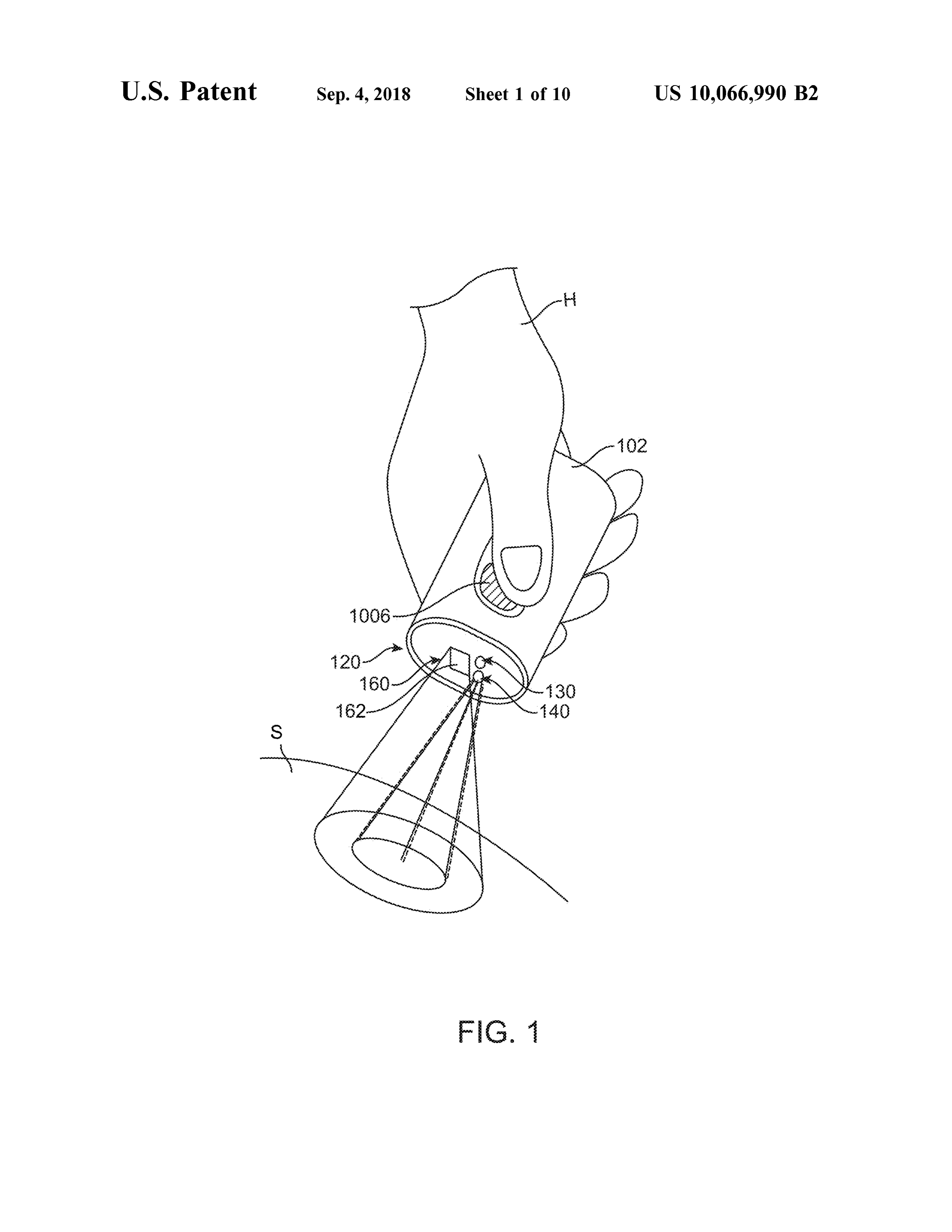
The novel features of the invention are set forth with As used herein , the term “ dispersive ” is used , with respect particularity in the appended claims. A better understanding to optical components , to describe a component that is of the features and advantages of the present invention will designed to separate spatially , the different wavelength com be obtained by reference to the following detailed descrip - ponents of a polychromatic beam of light. Non - limiting tion that sets forth illustrative embodiments , in which the 45 examples of " dispersive” optical elements by this definition principles of the invention are utilized , and the accompany include diffraction gratings and prisms. ing drawings of which : FIG . 1 shows an isometric view of a compact spectrom FIG . 1 shows an isometric view of an exemplary compact eter 102, in accordance with configurations. The spectrom spectrometer; eter 102 can be used as a general purpose material analyzer FIG . 2 shows a schematic diagram of an exemplary 50 for many applications. In particular, the spectrometer 102 optical layout for a compact spectrometer; can be used to identify materials or objects , provide infor FIG . 3 illustrates an exemplary light intensity distribution mation regarding certain properties of the identified mate on a linear variable filter, rials, and accordingly provide users with actionable insights FIG . 4 illustrates an exemplary configuration of a linear regarding the identified materials. The spectrometer 102 variable filter suitable for incorporation with a compact 55 comprises a spectrometer head 120 configured to be directed spectrometer; towards a sample material S . The spectrometer head 120 FIGS. 5A -5B illustrate another exemplary configuration comprises a spectrometer module 160 , configured to obtain of a linear variable filter suitable for incorporation with a spectral information associated with the sample material S . compact spectrometer ; The spectrometer module may comprise one or more optical FIG . 6A illustrates an exemplary configuration of a spa - 60 components , such as a linear variable filter, as described in tially variable filter suitable for incorporation with a com - further detail herein . The spectrometer module may further pact spectrometer ; comprise a spectrometer window 162 , through which inci FIG . 6B illustrates exemplary transmission profiles of the dent light from the sample material S can enter the spec plurality of different filters of FIG . 6A . trometer, to be subsequently measured by the optical com FIGS . 7A - 7C illustrate exemplary configurations of a 65 ponents of the spectrometer module . The spectrometer head spatially variable filter suitable for incorporation with a 120 may comprise an illumination module 140, comprising compact spectrometer ; a light source configured to direct an optical beam to the
Page 17
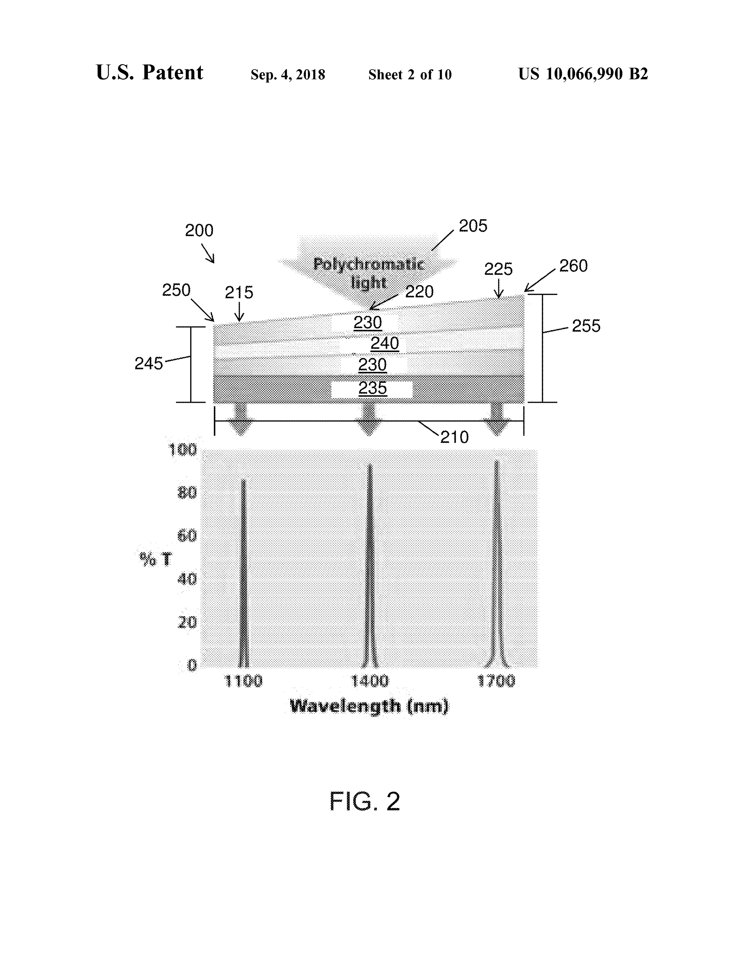
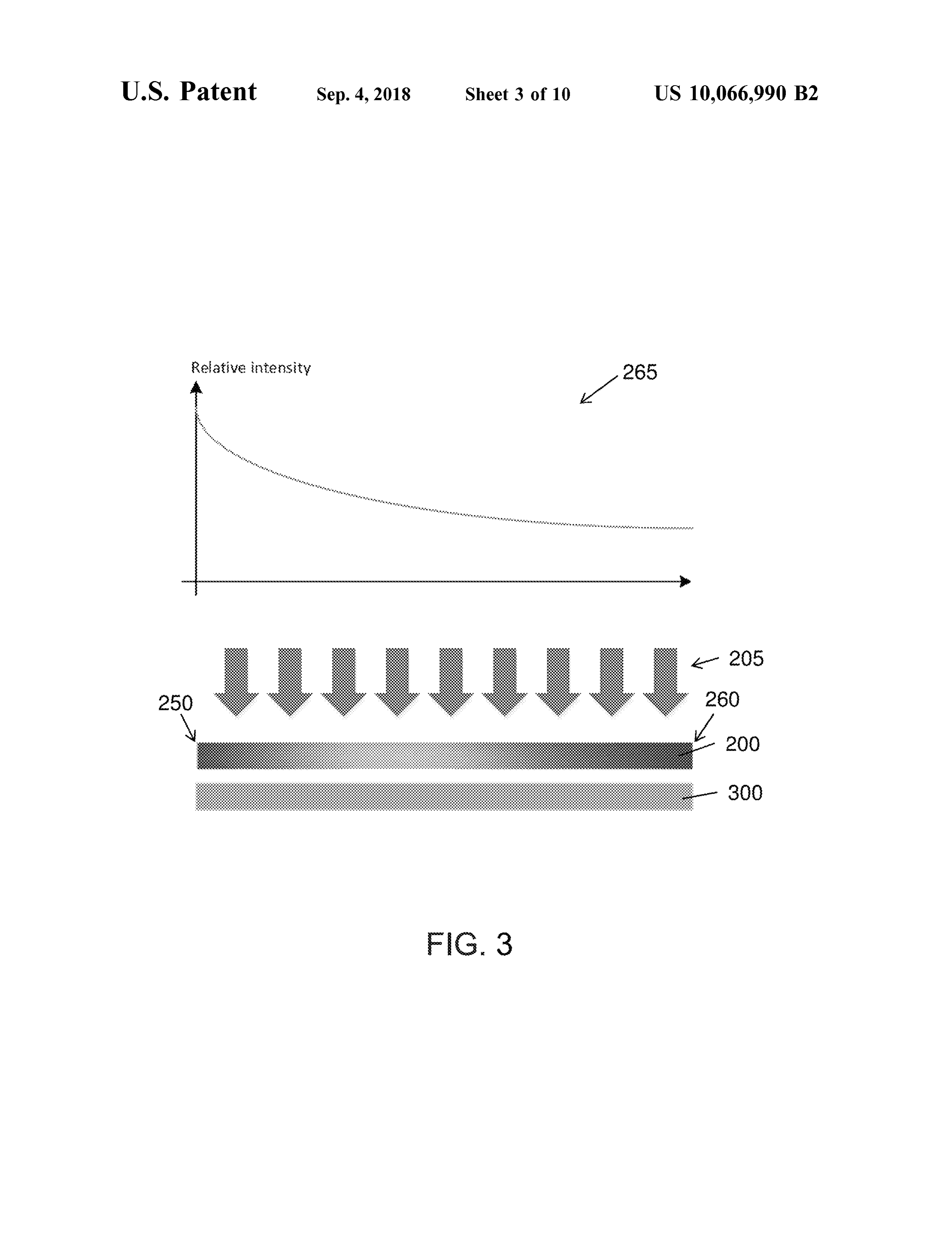
sample material S within the field of view of the detector. filter may be indistinguishable from true spectral variations The spectrometer head 120 may further comprise a sensor of the incident light, thus introducing " false " spectral varia module 130 , which may, for example , comprise a tempera tions or distortions into the measured spectra . For example , ture sensor. The spectrometer may comprise simple means if the spectrometer inputwindow is tilted with respect to the for users to control the operation of the spectrometer, such 5 sample plane, a first end 250 of a linear variable filter 200 , as operating button 1006 . The compact size of the spec - positioned behind the spectrometer window , may be closer trometer 102 can provide a hand held device that can be to the sample surface than a second end 260 of the filter. directed (e. g., pointed ) at a material to rapidly obtain infor - Accordingly , as shown in graph 265 , the incident light may mation about the material. For example , as shown in FIG . 1 , impinge upon the first end 250 of the filter at a higher the spectrometer 102 may be sized to fit inside the hand H 10 intensity than at the second end 260 of the filter. A detector of a user. or sensor 300, optically coupled to the linear variable filter FIG . 2 illustrates the principle of operation of an exem to receive light transmitted through the filter, may then plary embodiment of a spatially variable filter , such as the detect a higher intensity of light having a wavelength linear variable filter 200 . One example of a spatially variable corresponding to the transmission profile of the first end of filter is a linear variable filter, configured to have a plurality 15 the filter, while detecting a relatively weaker intensity of of transmission profiles that vary linearly across a length of lighthaving a wavelength corresponding to the transmission the filter. Incident light 205 , reflected from a surface of a profile of the second end of the filter. In such a scenario , the sample material measured by the spectrometer, enters the differences in the detected intensity of light at different spectrometer through a spectrometer input window , and hits wavelengths would be at least partially attributable to the tilt the linear variable filter 200 . The linear variable filter 200 20 of the spectrometer, rather than to the true spectral compo can be configured to have a plurality of transmission profiles sition of the light reflected from the sample material. Such that vary linearly across a length 210 of the filter, each an outcome can distort the measured spectra of the sample transmission profile comprising a passband centered around depending on the tilt, position , or orientation of the spec a center wavelength (CWL) and having a bandwidth . For trometer, or on other sampling conditions that can introduce example , as shown in FIG . 2 , the filter can have a CWL of 25 similar distortions in the measured spectra . about 1100 nm at a first location 215 , a CWL of about 1400 compact spectrometer, such as the handheld spectrom nm at a second location 220 , and a CWL of about 1700 nm eter 102 shown in FIG . 1 , may often be used to measure a at a third location 225 along the length 210 of the filter. The sample at various positions and /or orientations with respect bandwidth of each passband can be , for example , about to the sample plane . Therefore , a spatially variable filter for 1 - 10 % of the corresponding CWL, such as about 1 nm to 30 incorporation with a compact spectrometer would benefit about 200 nm , depending on the passband CWL . Accord from having reduced variations in measured input light ingly , light 205 incident on the filter 200 can be spectrally intensity across the area of the filter, so as to improve the separated by the filter , based on the location at which the accuracy and reliability of spectral measurements of the incident light hits the filter. For example , as shown in FIG . same sample taken under different sampling conditions. 2 , only portions of the incident light having wavelengths of 35 Described herein are various exemplary embodiments of a about 1100 nm + the half bandwidth of the passband may be spatially variable filter suitable for incorporation with a transmitted through the filter at location 215. Similarly , only compact spectrometer, the spatially variable filter compris portions of incident light having wavelengths of about 1400 ing a plurality of spaced apart filter regions having similar nm : the half bandwidth of the passband may be transmitted transmission profiles in order to measure spatial variation of through the filter at location 220 , and only portions of 40 the input light energy incident on the spatially variable filter. incident light having wavelengths of about 1700 nm - the Each exemplary embodiment may comprise one or more half bandwidth of the passband may be transmitted through linear variable filters , discrete filters , or combinations the filter at location 225 . The spectrally separated light thereof. A linear variable filter , configured to have a plurality transmitted through the filter 200 can be detected by a of transmission profiles that vary linearly across a length of detector placed in series with the filter, such that the detector 45 the filter, is a special type of a spatially variable filter. Other can then measure the amount, or intensity, of incident light types of spatially variable filters having various configura at different wavelengths. tions and principles of operation are also described herein , The linear variable filter 200 may comprise one or more wherein each type of spatially variable filter may have a filter coatings 230 , such as bandpass filter coatings , coated different dependency between spatial locations and trans onto a substrate 235 . In some embodiments , the linear 50 mission profiles .
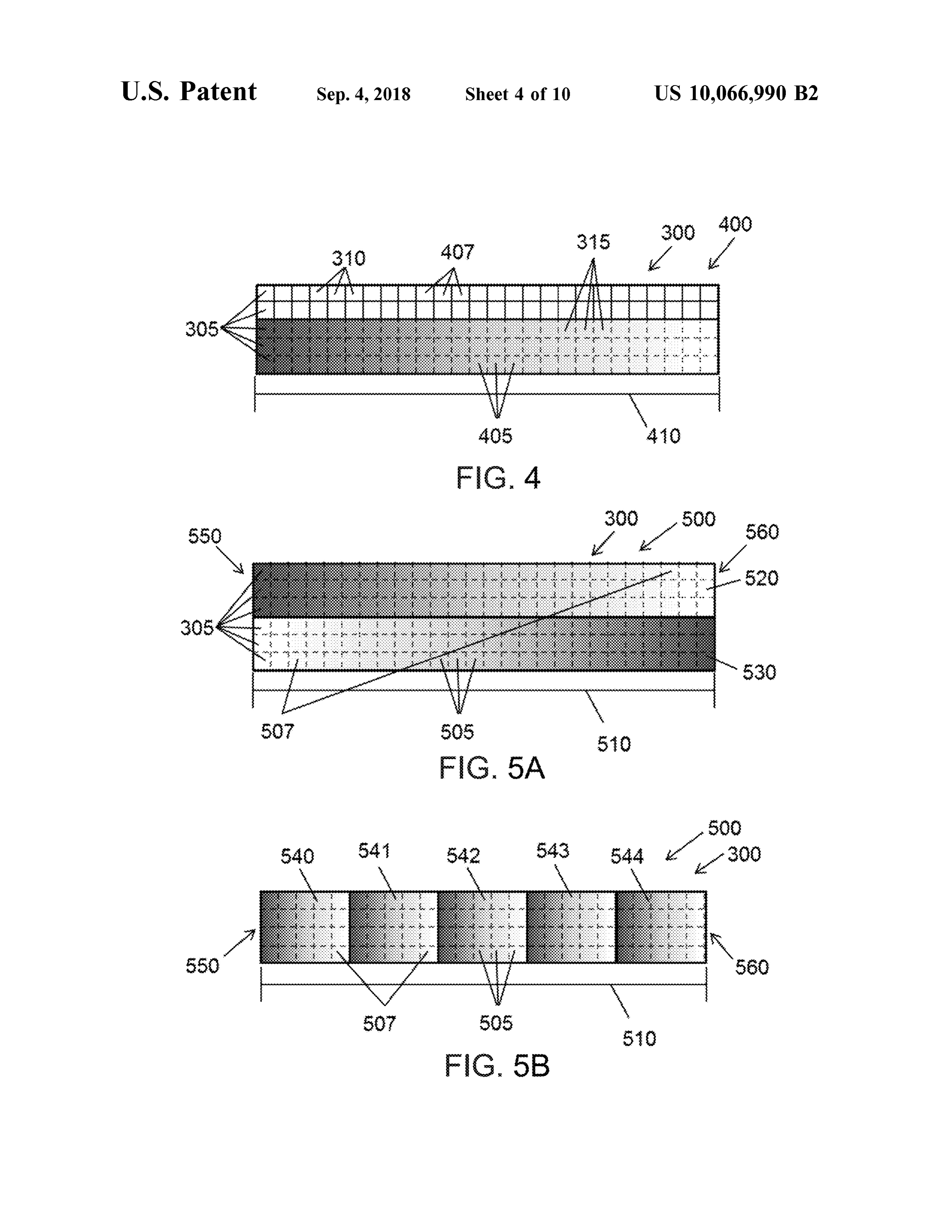
variable filter comprises two filter coatings 230 spaced apart FIG . 4 illustrates an exemplary configuration of a linear with a spacer 240, such that the total thickness of the filter variable filter 400 suitable for incorporation with a compact coating varies over the length 210 of the filter. For example , spectrometer. The linear variable filter 400 can be optically the thickness 245 of the filter coating at a first end 250 of the coupled to a detector 300 , such that light reflected from a filter may be smaller than the thickness 255 of the filter 55 sample surface first passes through the filter , and the spec coating on a second end 260 of the filter. A bandpass filter trally separated light then hits the detector. The detector 300 coating may be configured such that the passband CWL can comprise a plurality of detector elements 305 , such as varies as a function of coating thickness . Thus , a linear pixels . The detector may comprise , for example , an image variable filter having a thickness that varies linearly along its sensor such as a CCD or a 2 - D CMOS array . The filter 400 length can be configured to have a plurality of passband 60 may be spaced apart from or in contact with the detector. For CWL that vary linearly along the length of the filter . example , the filter may comprise a linear variable filter FIG . 3 illustrates an exemplary light intensity distribution coating that is at least partially deposited on separate detec on a spatially variable filter, such as the linear variable filter tor elements of the detector. Alternatively, the filter may 200 . As sampling conditions vary , light 205 from the sample comprise a support placed in proximity and configured to material incident on the spectrometer window may change 65 support and separate the detector elements in order to filter in absolute intensity and in relative intensity across the area light spatially among the separate detector elements . The of filter. Variations in relative intensity across the area of the filter 400 may be aligned with the detector 300 such that the
Page 18
light spectrally separated by the filter impinges upon at least comprise a more accurate representation of the spectral a portion of the detector elements . In many configurations, information of the measured sample . the filter and detector are aligned such that the spectrally Since the exposed pixels 310 receive unseparated light, separated light transmitted through the filter impinges upon the intensity of the signal recorded by the exposed pixels can the entire area of the detector. 5 be much greater than the intensity of the signal recorded by The linear variable filter 400 can comprise a plurality of the covered pixels 315 . In many instances , the difference different spaced apart regions 405 having different transmis between pixels the intensity of the signal recorded by the exposed and the covered pixels may be greater than the sion profiles, the transmission profiles varying linearly along the length 410 of the filter as described herein . Each filter dynamic range of the detector 300. Accordingly, the expo region 405 can comprise an area of the filter 400 configured 10 of sure time of the detector may be set such that overexposure the exposed pixels is avoided , though such an exposure to transmit light that is received by a detector element time may yield a relatively low detected signal for the operatively coupled to the filter region . The different trans covered pixels. One approach to compensate for the differ mission profiles may comprise full width half maximum ence in detected signal strength between the exposed and (FWHM ) ranges that are at least about 5 nm different ent from 15
Irom 15 covered detector pixels is to reduce the detected signal each other and/ or center wavelengths at least about 5 nm strength for the exposed pixels . For example, the linear different from each other, for example . The detector 300 may variable filter 400 may comprise a plurality of similar spaced comprise a plurality of detector elements such as pixels 305 , apart regions 407 having similar transmission profiles, such each detector element optically coupled to each of the that the incident light is transmitted through the similar different filter regions 405 of the filter 400 . The filter 400 and 20 regions 407 in a substantially uniform manner . Similar detector 300 can be aligned such that each pixel 305 transmission profiles may comprise, for example , center corresponds to a different location along the length 410 of wavelengths that are within a range from about 0 .01 nm to the filter. Each pixel 305 can be configured to record an about 5 nm of each another, and FWHM within a range from amount of the light detected by the pixel. The detected about 0 .01 nm to about 5 nm of each another. The similar intensity of light at each pixel can correspond to the intensity 25 regions 407 may comprise a neutral density filter, or any of the incident light at a range of wavelengths determined by type of uniform intensity filter configured to have a sub the transmission profile of the corresponding filter region stantially fixed transmission profile along its length . Alter 405 . The detector 300 can be operatively coupled to a natively or in combination , the similar filter regions 407 may processor configured to receive data from the detector, and comprise a plurality of separate aperture elements or par output spectral data in response to transmitted light intensity 30 tially occluding structures placed over each detector element at the plurality of different filter regions 405 . 305 , to reduce the amount of light received by each exposed As described herein , spectral data generated using a linear pixel 310 . The similar filter regions 407 may extend along a variable filter can be distorted by the effect of incident light distance comprising at least half of a maximum distance intensity variations across the area of the filter. To address across the sensor, such as the length 410 of the filter. Another this issue , the linear variable filter 400 and the detector 300 35 approach to compensate for the detected signal strength may be configured such that at least a portion of the detector difference between the covered and exposed pixels is to elements 305 of the detector receive incident light from the configure different portions of the detector to have different sample that has not been spectrally separated by the filter exposure times . For example , the covered pixels , configured 400. For example , the detector 300 can comprise “ exposed ” to receive light transmitted through the different filter pixels 310 and “ covered " pixels 315 , wherein the exposed 40 regions 405 , can be configured to have an exposure time that pixels 310 receive unseparated incident light and the cov - is longer than the exposure time of the exposed pixels , ered pixels 315 receive spectrally separated light transmitted configured to receive light transmitted through the similar through the filter 400 . In configurations where the filter 400 filter regions 410 .
comprises a separate filter unit placed in series with the FIGS. 5A and 5B illustrate another exemplary configu detector 300 , the filter unit can have an area that is smaller 45 ration of a spatially variable filter 500 suitable for incorpo than the area of the detector so as to leave some of the ration with a compact spectrometer. The spatially variable detector pixels exposed , or the filter unit and the detector filter 500 can be optically coupled to a detector 300 com may be aligned so as to have a non - overlapping area . In prising a plurality of detector elements such as pixels 305 , embodiments where the filter 400 comprises a filter coating as described in further detail in reference to the embodiment deposited directly onto the detector 300 , the filter coating 50 of FIG . 4 . The spatially variable filter 500 can comprise a may be deposited over only a portion of the detector plurality of different spaced apart regions 505 having dif elements , so that a remaining portion of the detector ele - ferent transmission profiles, the transmission profiles vary ments remains uncoated . Preferably, the exposed pixels 310 ing linearly along the length 510 of the filter as described extend over the entire length 410 of the linear variable filter herein . Each filter region 505 can comprise an area of the 400 , such that the exposed pixels can determine the distri- 55 filter 500 configured to transmit light that is received by a bution of light intensity across the entire length , and there - detector element operatively coupled to the filter region . The fore over the entire spectrum , of the linear variable filter . different transmission profiles may comprise full width half The exposed pixels 310 can record the intensity variation maximum (FWHM ) ranges that are at least about 5 nm of the incident light across the area of the detector 300 , different from each other and/or center wavelengths at least providing a way ofmeasuring spatial variations of incident 60 about 5 nm different from each other , for example . The light intensity across the area of the filter 400 . The light detector 300 may comprise a plurality of detector elements distribution recorded by the exposed pixels can subsequently such as pixels 305 , each detector element optically coupled be used to reduce the contribution of spatial variations in to each of the different filter regions 505 of the filter 500 . The light intensity in the output spectra . A processor coupled to filter 500 and detector 300 can be aligned such that each the detector may be configured with instructions to adjust 65 pixel 305 corresponds to a different location along the length the output spectral data in response to the detected spatial 510 of the filter. Each pixel 305 can be configured to record intensity variations of light. The adjusted spectral data can an amount of the light detected by the pixel. The detected
Page 19
intensity of light at each pixel can correspond to the intensity normalized or adjusted spectral data can comprise a more of the incident light at a range of wavelengths determined by accurate representation of the spectral information of the the transmission profile of the corresponding filter region . measured sample .
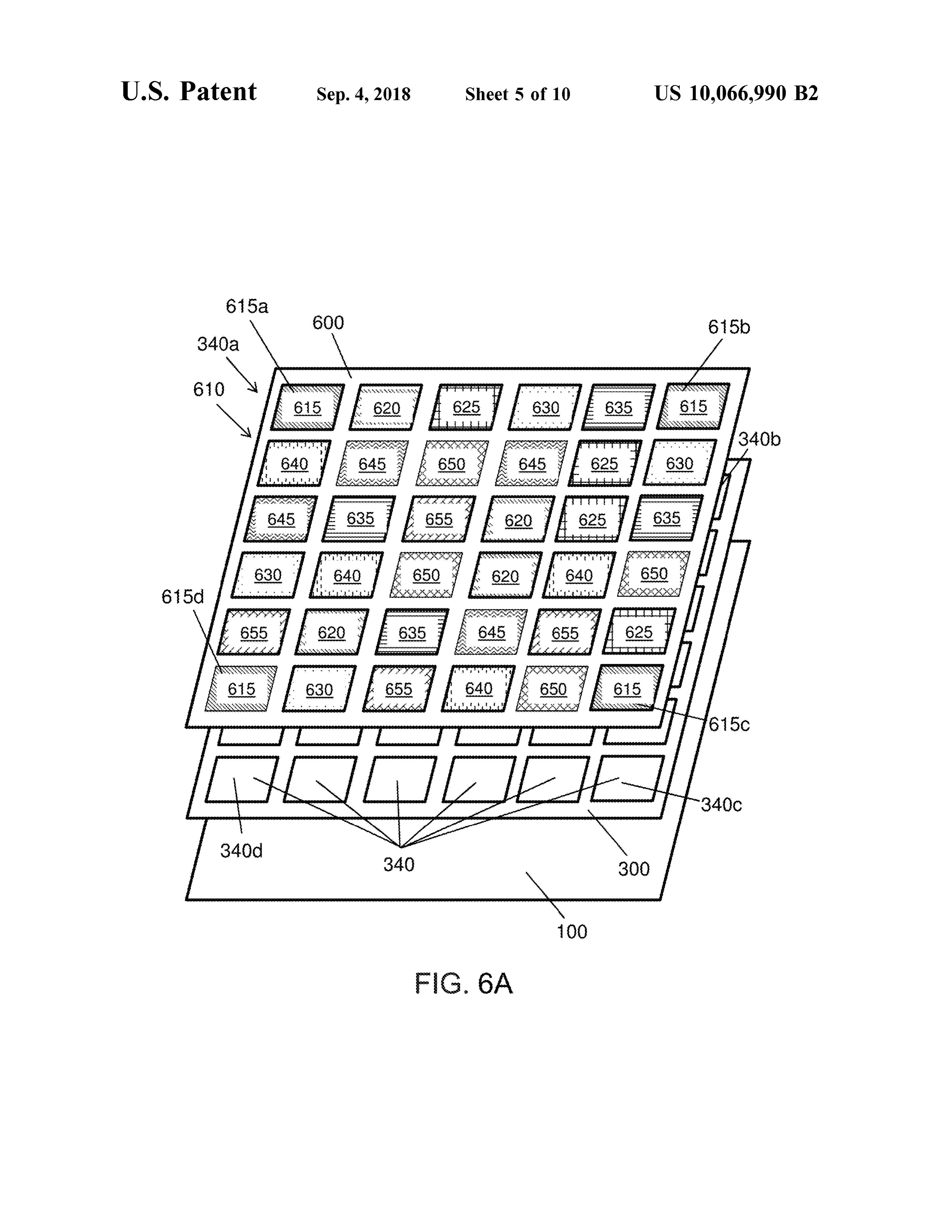
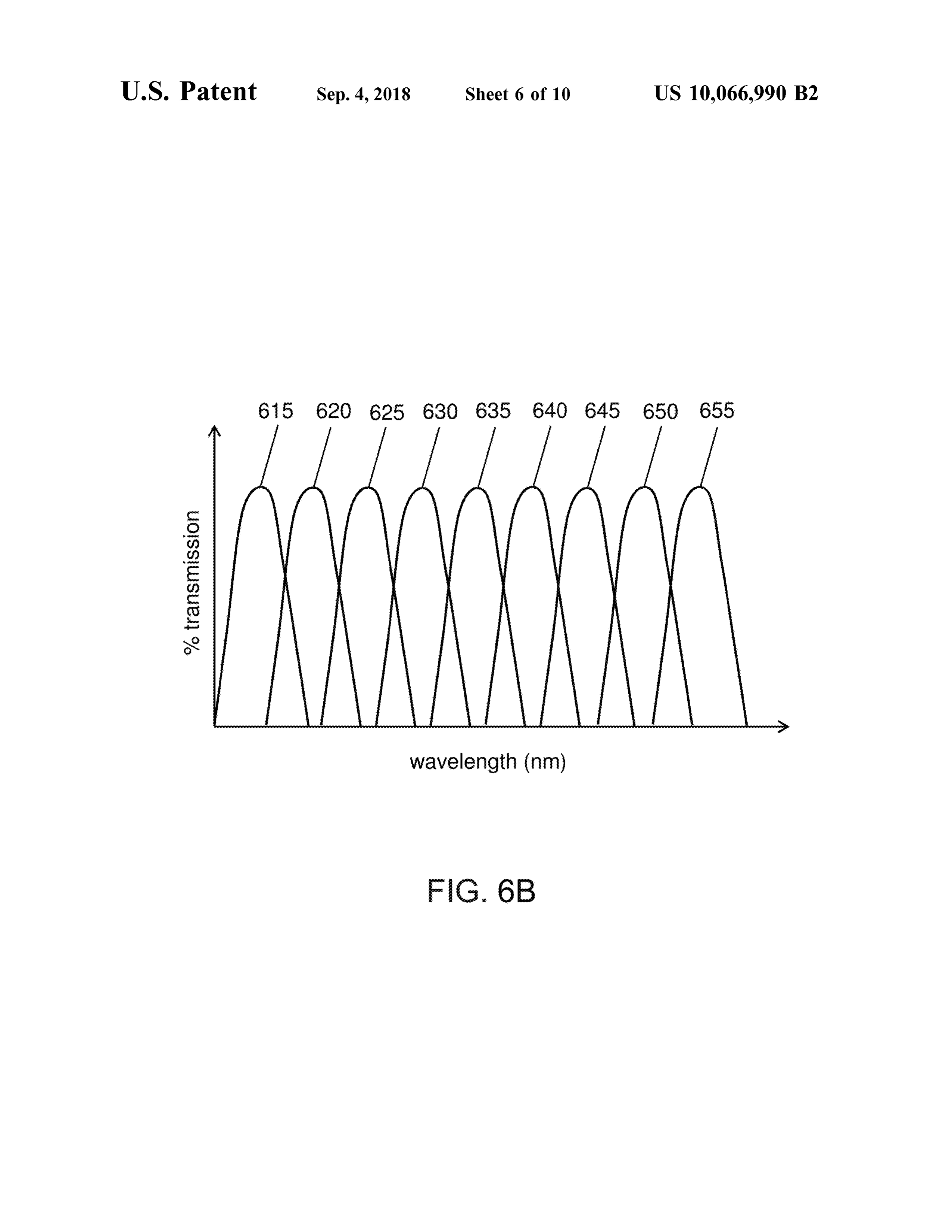
The detector 300 can be operatively coupled to a processor While FIG . 5A shows the spatially variable filter 500 configured to receive data from the detector, and output 5 having two linear variable filter elements positioned in spectral data in response to transmitted light intensity at the linearly opposite directions, filter 500 may comprise a plurality of different filter regions 505 . plurality of spatially variable filter elements of any number As described herein , spectral data produced using a spa - and any suitable orientation to allow algorithmic compen tially variable filter can be distorted by the effect of incident sation for relative intensity variations of the incident light. light intensity variations across the area of the filter. To 10 The detector 300 can comprise detector elements configured address this issue, the spatially variable filter 500 can to measure the intensity of light transmitted through the comprise a plurality of similar spatially variable filter ele - plurality ofdifferent and similar filter regions of any number ments , such that the filter comprises a plurality of similar and / or spatial distribution across the filter 500 . Accordingly , spaced apart filter regions 507 distributed over the area of while the compensation algorithm has been described as an the filter. Similar filter regions 507 may have similar trans- 15 averaging of measurement data with respect to the configu mission profiles, for example comprising center wave - ration shown in FIG . 5A , any appropriate algorithm may be lengths that are within a range from about 0 .01 nm to about used to adjust the measured spectral data to reduce spatial 5 nm of each another, and/ or FWHM within a range from variation of light intensity across the area of the filter 500 . about 0 .01 nm to about 5 nm of each another. Spectral data For example, as shown in FIG . 5B , spatially variable filter generated with detector elements 305 coupled to the similar 20 500 may comprise a plurality of adjacent filter elements 540 , filter regions 507 can be used to determine a spatial variation 541, 542, 543 , and 544 concatenated one after another. Each in the intensity of the incident light, since the detector filter element can be a linear variable filter configured to elements can detect light having similar transmission pro spectrally separate light over the full measured spectrum . files impinging upon the filter 500 at different locations . The Each filter element may comprise a plurality of different output spectra may then be adjusted to reduce the spatial 25 filter regions 505 having different transmission profiles. variation in the intensity of incident light. Collectively , the filter 500 may also comprise a plurality of For example, as shown in FIG . 5A , the filter 500 may similar filter regions 507 having similar transmission pro comprise two similar linear variable filter elements 520 and files, at a plurality of non - adjacent locations of the filter 500 . 530 , oriented in opposite directions with respect to the two The detector 300 may comprise a plurality of detector ends 550 and 560 of the filter 500 . For example , if filter 30 elements coupled to each filter region of the filter 500 , in element 520 is oriented to transmit light of about 1100 nm which each detector element is configured to measure the at end 550 and about 1700 nm at end 560 , the filter element intensity of light transmitted through the filter region . The 530 may be oriented to transmit light of about 1700 nm at plurality of detector elements coupled to each filter element end 550, and 1100 nm at end 560. The filter elements 520 can produce a complete spectral representation of the inci and 530 can have similar linearly varying transmission 35 dent light . The plurality of spectral representations obtained profiles , such that the filter comprises a plurality of similar from a plurality of detector elements coupled to similar filter filter regions 507 having similar transmission profiles posi- regions having similar transmission profiles can be com tioned at different locations of the filter 500. Detector pared with one another, in order to determine the intensity elements 305 of the detector 300 may be configured to variation of the incident light, if any, across the area of the measure the intensity of the light transmitted through the 40 filter 500 . The determined intensity variation can be factored plurality of similar filter regions 507 . If the incident light into a data analysis algorithm to compensate for the mea does not contain any intensity variations across the area of sured intensity variations across the filter area . the filter 500 , the data collected by the detector elements FIG . 6A illustrates an exemplary configuration of a spa coupled to the similar filter regions 507 will be similar or t ially variable filter 600 suitable for incorporation with a substantially identical. However , if the incident light con - 45 spectrometer. The spatially variable filter 600 may comprise tains intensity variations across the area of the filter 500 , the a two -dimensional array 610 composed of a plurality of filter data collected by the detector elements coupled to the regions. Each filter region can comprise an area of the filter similar filter regions 507 will be different . For example , the 600 configured to transmit light that is received by a detector incident light may comprise a linear gradient along the element operatively coupled to the filter region . The filter length 510 of the filter 500 , such that the intensity of the 50 600 may comprise a plurality of different spaced apart filter incident light is stronger at end 550 than at end 560 . In this regions having different transmission profiles at different case , the detector elements coupled to filter region 507 of the locations. The plurality of different filter regions may com filter element 530 will detect a higher intensity of light prise a plurality of discrete filter elements . Alternatively or compared to the detector elements coupled to filter region in combination , the plurality of different filter regions may 507 of the filter element 520 . 55 comprise a plurality of spaced apart regions of a single , If the measurement data collected by the plurality of continuous filter element, wherein each of the plurality of detector elements coupled to the plurality of similar filter regions comprises a unique transmission profile (e. g., as in regions 507 indicate the presence of a spatial variation in the a linear variable filter ). Each different filter region can be intensity of incident light, a data analysis algorithm may be configured to transmit a range of wavelengths distributed applied to reduce the spatial variation in the output spectra . 60 about a central wavelength . The array 610 may comprise, for A processor coupled to the detector may be configured with example , a plurality of bandpass filters having passband instructions to adjust the output spectral data in response to widths in a range from about 1 nm to about 200 nm , for the detected spatial intensity variations of light. For example . In the example shown in FIG . 6A , the spatially example , in the case of incident lighthaving a linear gradient variable filter 600 comprises different filter regions 615 , 620 , in intensity across the length 510 of the filter 500 , the 65 625 , 630 , 635 , 640 , 645 , 650 , and 655 configured to have measurement data generated by detector elements coupled to different transmission profiles as described herein . FIG . 6B a plurality of similar filter regions may be averaged . Thus, illustrates exemplary different transmission profiles of the
Page 20
plurality of different filter regions of FIG . 6A . The different FIG . 6A , detector element 340a can be configured to record transmission profiles may comprise full width half maxi the intensity of light transmitted through filter region 615a , mum (FWHM ) ranges that are at least about 5 nm different detector element 340b can be configured to record the from each other and / or center wavelengths at least about 5 intensity of light transmitted through filter region 615b , nm different from each other, for example . Each of the 5 detector element 340C can be configured to record the different filter regions may have a transmission profile that intensity of light transmitted through filter region 615c, and partially overlaps and/or does not overlap with the trans detector element 340d can be configured to record the mission profile of another different filter of the array. intensity of light transmitted through filter region 615d . If Together, the plurality of different filters of the spatially the incident light is uniform in intensity across the area of variable filter can spectrally separate the light incident on the 10 the filter 600 , the detector elements coupled to the plurality filter. of similar filter regions may detect similar signal intensities . The spatially variable filter 600 may further comprise a For example , each of detector elements 340a , 340b , 340C, plurality of similar spaced apart filter regions having similar and 340d may detect similar signal intensities for the spec transmission profiles that are different from other transmis - tral component of the incident light corresponding to the sion profiles of the array. The plurality of similar filter 15 transmission profile of filter region 615 . If the incident light regions may comprise a plurality of discrete filter elements . varies in intensity across the area of the filter 600 , the Alternatively or in combination , the plurality of similar filter detector elements coupled to the plurality of similar filter regions may comprise a plurality of spaced apart regions of regions may detect varying signal intensities. For example , a single , continuous filter element, wherein the same con - each of detector elements 340a , 340b , 340c , and 340d may tinuous filter element may also comprise a plurality of 20 detect a different signal intensity for the spectral component different filter regions as described herein . The plurality of of the incident light corresponding to the transmission similar spaced apart filter regions can be positioned at a profile of filter region 615 . Thus, a filter array having two or plurality of locations of the spatially variable filter in order more similar filter regions with the same transmission pro to detect spatial variations of the incident light profile . Thus, file , distributed in different spatial locations of the filter at least one of the different transmission profiles of the 25 array, can help detect the presence of incident light intensity spatially variable filter can be repeated at a plurality of variations across the area of the filter, as well as the pattern spaced apart regions of the spatially variable filter. For of the intensity variation .
example , as shown in FIG . 6A , the spatially variable filter processor 100, operatively coupled to the detector 300 , 600 may comprise four similar filter regions 615a, 615b, can receive measurement data from the detector, and output 6150, and 615d having a similar transmission profile . Simi- 30 spectral data in response to the transmitted light intensity at lar transmission profiles may comprise , for example , center the plurality of similar and different filter regions. The wavelengths that are within a range from about 0 .01 nm to processor may comprise a tangible medium configured with about 5 nm of each another, and FWHM within a range from instructions to receive input spectral data , the input spectral about 0 .01 nm to about 5 nm of each another. The filter 600 data comprising similar spectral data generated by the preferably comprises at least two similar spaced apart 35 plurality of similar filter regions at a plurality of locations of regions having similar transmission profiles, wherein the the detector array . The processormay be further configured two spaced apart regions may be at non -adjacent locations of to determine a spatial variation of the intensity of incident the filter . For example , the two similar filter regions can be light across the area of the filter 600 . For example , the spatially separated by a distance comprising at least half of processormay comprise instructions to compare the spectral the maximum distance across the spatially variable filter. In 40 data generated by the plurality of detector elements coupled the configuration shown in FIG . 6A , similar filter regions to the plurality of similar filter regions , thereby identifying 615a , 615b , 6150 , and 615d can be located , respectively, in any discrepancies in the spectral data generated by the the upper left hand corner , upper right hand corner , lower similar filter regions at different locations of the spatially right hand corner, and lower left hand corner of the filter 600 variable filter. The processor may further comprise instruc to detect spatial variations of light incident on the array. 45 tions to generate output spectral data in response to the A detector 300 , such as an image sensor as described similar spectral data . The processor may be configured to herein , may be operatively coupled to the spatially variable adjust the output spectra in response to any detected inten filter 600, such that the incident light spectrally separated by sity variations among the plurality of similar filters at a the filter is subsequently detected by the detector. The plurality of locations. For example , the processor may detector may comprise a plurality of detector elements 340 . 50 comprise instructions to apply an appropriate algorithm to Each detector element is optically coupled to each of the adjust the measurement data generated by the detector, so as plurality of similar filter regions and each of the plurality of to reduce the effect of any spatial non -uniformity in the different filter regions. The plurality of detector elements intensity of the sample light on the output spectra . The may be configured in a two - dimensional array positioned in recorded signal intensity for a particular spectral component alignment with the filter array 610 . Each detector element 55 of the incident lightmay, for example , be averaged across all may comprise of plurality of pixels configured to detect the similar filter regions of the filter array configured to have incident light. The filter 600 may be spaced apart from or in similar transmission profiles .
contact with the detector 300 . For example , the filter may spatially variable filter may have any number of dif comprise a plurality of bandpass filter coatings at least ferent filter regions having different transmission profiles , partially deposited on the detector elements , or the filter may 60 and each different transmission profile may be repeated at comprise a separate filter unit placed in series and aligned any number of spaced apart regions of the spatially variable with the detector elements . Each of the plurality of filter filter so as to provide a plurality of similar filter regions. For regions of the filter 600 may be deposited on each of example , a spatially variable filter as described herein may plurality of detector elements . comprise at least N different filter regions having N different Each of the similar filter regions of the filter array, such 65 transmission profiles, wherein N is an integer within a range as filters 615a , 615b , 615c, and 615d , can be optically from about 3 to about 1 ,000 , 000 . For example , N may be at coupled to a detector element 340 . For example, as shown in least 5 , at least 6 , at least 7 , at least 8 , at least 9 or at least
Page 21
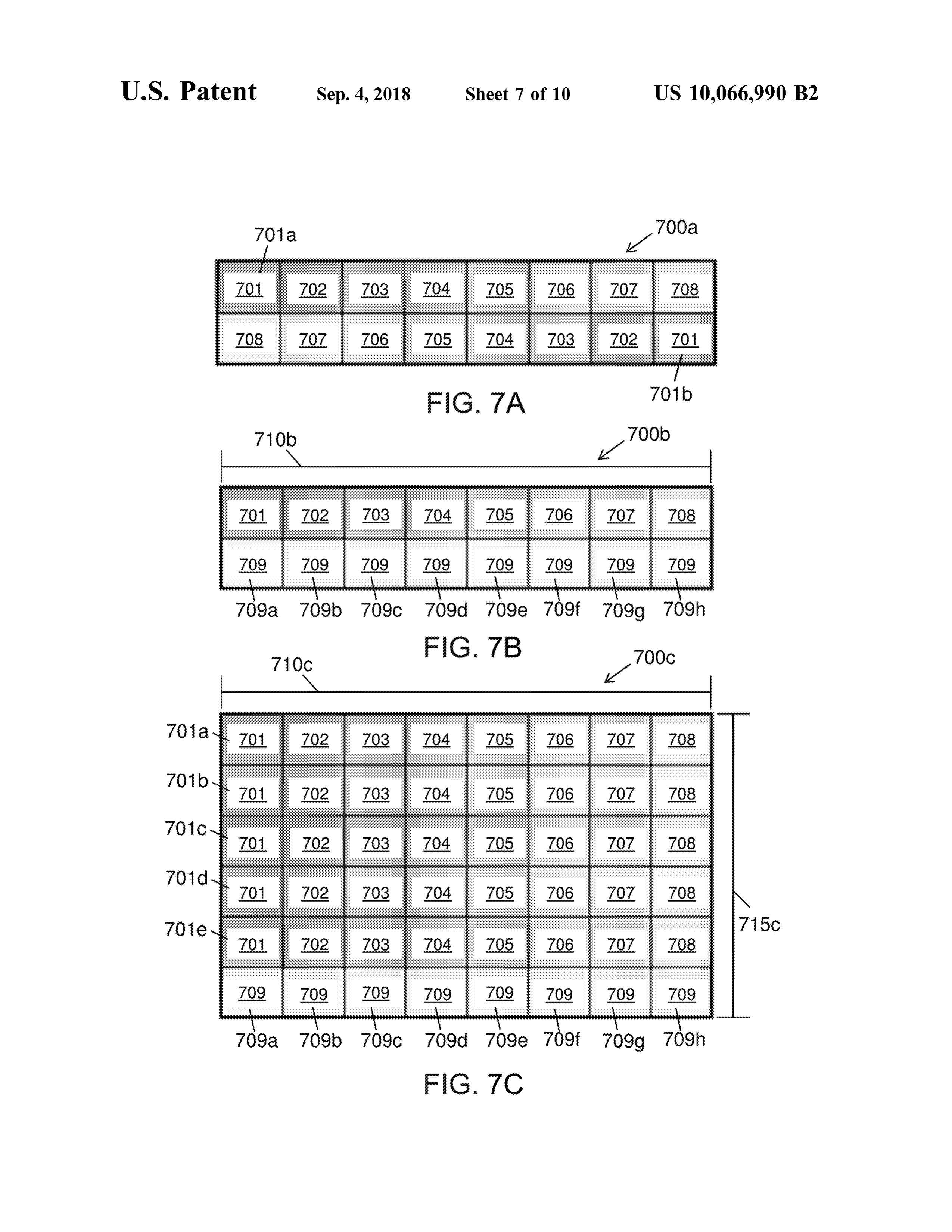
10 , for example. At least one of the N different transmission locations (M2 = 8 ). Each of the 8 different transmission profiles may be repeated at M spaced apart regions of the profiles of filter regions 701, 702 , 703 , 704 , 705 , 706 , 707, spatially variable filter, wherein M is an integer within a and 708 is repeated at 5 different locations along the width range from about 2 to about 100 . For example , M may be at 715c of filter 700c , such that the filter 700c comprises 5 least two. N may be greater than M , or M may be greater 5 similar filter regions for each of the transmission profiles. than N . N may be at least five times M , or N may be at least For example , as shown in FIG . 7C , the transmission profile one hundred times M . Each different transmission profile of filter region 701 is repeated at 5 different locations , may be repeated at a different number of spaced apart yielding similar filter regions 701a , 701b , 701c , 701d , and regions of the spatially variable filter. For example , a first 701e having a similar transmission profile . The transmission transmission profile may be repeated at two spaced apart 10 profile of filter region 709 is repeated at 9 different locations regions so as to provide two similar filter regions having the along the length 710c of the filter 700c, such that filter 700c first transmission profile, while a second transmission profile comprises 9 similar filter regions having similar transmis different from the first transmission profile may be repeated sion profiles. As shown in FIG . 7C , the transmission profile at five spaced apart regions so as to provide five similar filter of filter region 709 is repeated at 8 different locations, regionshaving the second transmission profile . The different 15 yielding 8 similar filter regions 709a , 709b , 709c , 709d , filter regions and similar filter regions of the spatially 7 09e , 709f, 709g , and 709h .
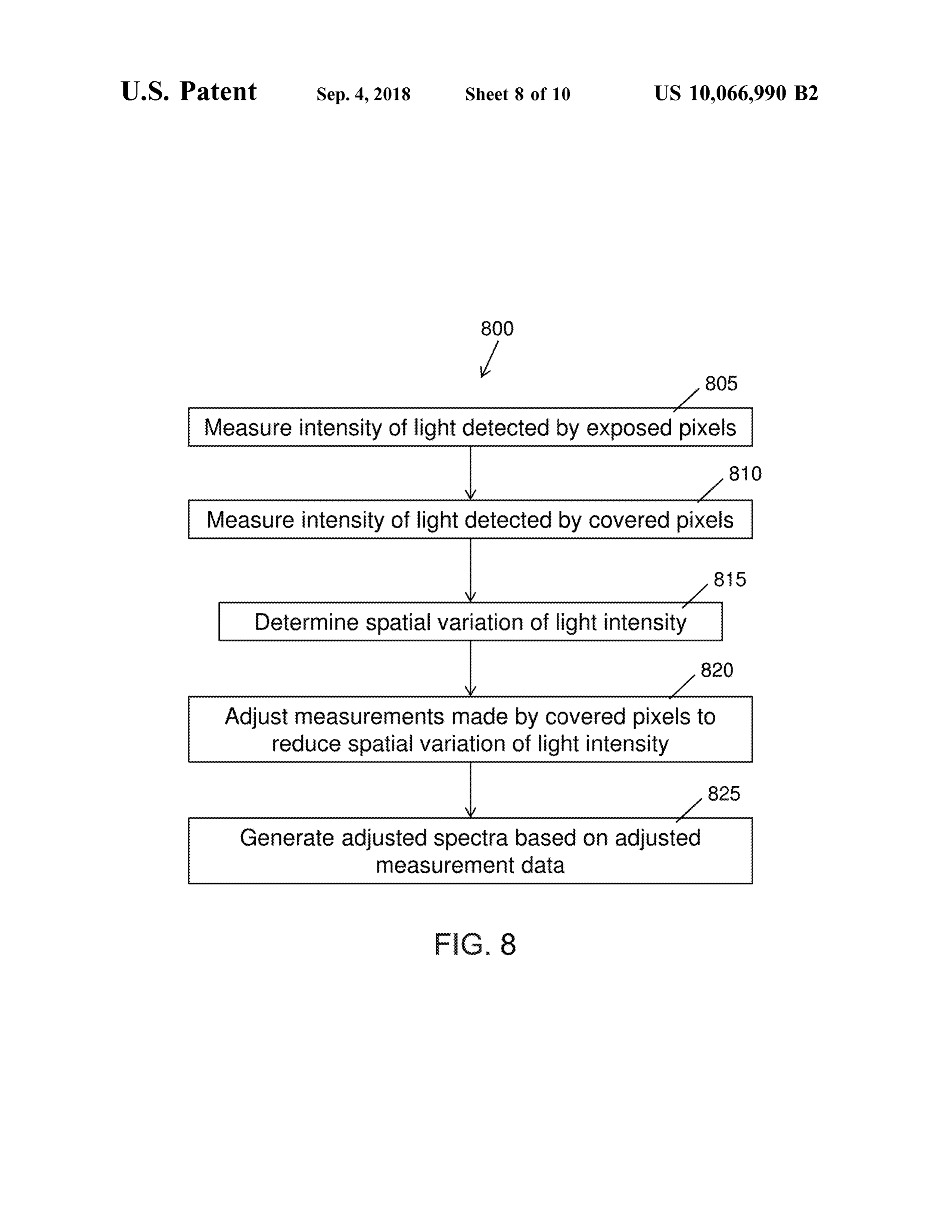
variable filter may be distributed in any spatial pattern . Each FIG . 8 is a flow chart illustrating a method 800 of filter region may comprise any transmission profile suitable reducing measured intensity variations across an area of a for collecting spectral representations of a sample material, linear variable filter 400 as shown in FIG . 4 . In step 805 , the such that collectively, the filter array can spectrally separate 20 intensity of light incident on the filter 400 is measured by the the incident light to generate a spectral representation of the covered pixels , or the pixels of a detector receiving light incident light. spectrally separated by a plurality of different filter regions FIGS. 7A - 7C illustrate exemplary configurations of a of the filter 400 . In step 810 , the intensity of light incident spatially variable filter suitable for incorporation with a on the filter 400 is measured by the exposed pixels, or the spectrometer. In these exemplary configurations and in other 25 pixels of the detector receiving unseparated light, wherein configurations of a spatially variable filter as described the unseparated lightmay be transmitted through a plurality herein , the spatially variable filter comprises a plurality of of similar filter regions of the filter 400 . The exposed pixels different filter regions and a plurality of similar filter regions can measure the variation , if any, of the incident light across wherein the plurality of filter regions may comprise a the area of the filter 400 , by recording the intensity distri plurality of discrete filter elements , a plurality of spaced 30 bution of the spectrally unseparated light over the length of apart regions of a single , continuous filter element, or a the linear variable filter. In step 815 , the spatial variation of combination thereof. Each filter region can comprise an area light intensity on the filter is determined , by analyzing the of the filter configured to transmit light that is received by a signals measured by the exposed pixels . Step 815 can detector element operatively coupled to the filter region . comprise, for example , determining the pattern and/or gra FIG . 7A illustrates a spatially variable filter 700a comprising 35 dient of the variation of light intensity across the length of 8 different filter regions (N = 8 ), each of which is repeated at the linear variable filter 400 . In step 820 , the measurements 2 spaced apart regions of the filter 700a to provide 2 similar made by the covered pixels of the detector are adjusted to filter regions (M = 2 ). Each of the 8 different filter regions reduce the spatial variation of light intensity determined in 701, 702 , 703, 704 , 705 , 706 , 707 , and 708 can be configured step 815 . For example, signals recorded by covered pixels to have a unique transmission profile . Each different trans - 40 corresponding to locations of relatively high light intensity mission profile is repeated at two spaced apart regions of the can be adjusted downwards by an appropriate amount, while filter 700a, such that the filter 700a comprises two similar signals recorded by covered pixels corresponding to loca filter regions for each different transmission profile . As tions of relatively low light intensity can be adjusted shown , filter region 701having a unique transmission profile upwards by an appropriate amount. In step 825 , adjusted is repeated at two spaced apart regions of the filter 700a to 45 sample spectra are generated based on the adjusted mea provide two similar filter regions 701a and 701b having surement data .
similar transmission profiles. Filter region 701a is located at FIG . 9 is a flow chart illustrating a method 900 of the upper left hand corner of the filter 700a , while 701b is reducing measured intensity variations across an area of a located at the lower righthand corner of the filter 700a . FIG . spatially variable filter 500 as shown in FIGS. 5A and 5B . In 7B illustrates a spatially variable filter 700b comprising 9 50 step 905 , the intensity of light incident on a first spatially different filter regions (N = 9 ), only one of which is repeated variable filter element is measured by a detector receiving at 8 spaced apart regions of the filter 700b to provide 8 light transmitted through the first filter element. In step 910 , similar filter regions ( M = 8 ). Each of the 9 different filter the intensity of light incident on a second spatially variable regions 701, 702, 703 , 704, 705 , 706 , 707 , 708 , and 709 can filter element is measured by the detector receiving light be configured to have a unique transmission profile . The 55 transmitted through the second filter element . In embodi transmission profile of filter region 709 is repeated at 8 ments of the filter 500 that comprise more than two filter different locations of the filter 700b to provide 8 similar filter elements , step 910 may be repeated as many times as regions 709a , 7096 , 709c, 709d , 709e, 7095, 709g , and 709h necessary to collect data from all filter elements. In step 915 , having similar transmission profiles . Each similar filter the spatial variation of light intensity on the filter is deter region is disposed at a different location of the spatially 60 mined , by comparing the spectra of light transmitted through variable filter 700b, for example at different locations along the two or more spatially variable filter elements. Step 915 the length 710b of the filter 7006 . FIG . 7C illustrates a can comprise , for example , determining the pattern and /or spatially variable filter 700c comprising 9 different filter gradient of the variation of light intensity across the length regions ( N = 9 ) each having a unique transmission profile , of the spatially variable filter 500 . In step 920 , the detector wherein 8 of the different transmission profiles are repeated 65 measurements are adjusted to reduce the spatial variation of at 5 different locations ( M = 5 ), and wherein one of the light intensity determined in step 915 . For example , if the different transmission profiles is repeated at 8 different incident light is determined to have a linear gradient in step
Page 22
915 , the measurements made by the two or more filter a processor configured with instructions to receive data elements for a particular spectral component of light can be from the detector and output spectral data to determine averaged . In step 925 , adjusted sample spectra are generated a spectrum in response to transmitted light intensity at based on the adjusted measurement data . the plurality of similar spaced apart filter regions and FIG . 10 is a flow chart illustrating a method 1000 of 5 the plurality of different spaced apart filter regions . reducing measured intensity variations across an area of a 2 . The spectrometer of claim 1 , wherein the processor is spatially variable filter 600 as shown in FIG . 6A . In step configured with instructions to adjust the output spectral 1005 , the intensity of light incident on a plurality of different data in response to spatial intensity variations of light filter regions and a plurality of similar filter regions of the incident on the spatially variable filter. filter 600 is measured , wherein the similar filter regions are 10 3 . The spectrometer of claim 1 , wherein the processor is configured to have similar transmission profiles and are configured with instructions to adjust the output spectral positioned in a plurality of locations of the filter array of data in response to transmitted light intensity variations filter 600 , as described herein . In step 1010 , the measure among the plurality of similar spaced apart filter regions. ments across the similar filter regions are compared . In step 4 . The spectrometer of claim 1, wherein the plurality of 1015 , the spatial variation of light intensity on the filter is 15 detector elements comprises a first plurality of detector determined , based on the comparison of measurements elements coupled to the spatially variable filter at each of the across the similar filter regions performed in step 1010 . Step first plurality of similar spaced apart filter regions and 1015 can comprise , for example , determining the pattern wherein the plurality of detector elements comprises a and/ or gradient of the variation of light intensity across the second plurality of detector elements coupled to the spatially area of the spatially variable filter 600 . In step 1020 , the 20 variable filter at each of the second plurality of different detector measurements are adjusted to reduce the spatial variation of light intensity determined in step 1015 . For 5 . The spectrometer of claim 1, wherein the plurality of example, if the incident light is determined to vary across the similar spaced apart filter regions comprises at least two area of the filter , the measurements made by the plurality of similar filter regions spaced apart by a distance comprising similar filters can be averaged . In step 1025 , adjusted sample 25 at least half of a maximum distance across the detector . spectra are generated based on the adjusted measurement 6 . The spectrometer of claim 1 , wherein the spatially data . variable filter comprises one or more of a linear variable For all methods described herein , many variations and filter having a variable spectral transmission profile , a plu modificationsmay bemade based on the disclosure provided rality of discrete filter elements having separate discrete herein . For example , some steps may be added , removed , or 30 transmission profiles , a neutral density filter , a uniform substituted . Some of the steps may comprise sub -steps, and intensity filter , a plurality of separate aperture elements , or many of the steps can be repeated . a plurality of separate partially occluding structures . Although the detailed description contains many specif- 7 . The spectrometer of claim 6 , wherein one or more of ics , these should notbe construed as limiting the scope of the the neutral density filter or the uniform intensity filter disclosure but merely as illustrating different examples and 35 extends along a distance comprising at least half of a aspects of the present disclosure . It should be appreciated maximum distance across the detector, the one or more of that the scope of the disclosure includes other embodiments the neutral density filter or the uniform intensity filter not discussed in detail above. Various other modifications, comprising a substantially fixed transmission profile along changes and variations which will be apparent to those the distance .
skilled in the artmay be made in the arrangement, operation 40 8 . The spectrometer of claim 1 , wherein the spatially and details of the method and apparatus of the present variable filter has been at least partially deposited on sepa disclosure provided herein without departing from the spirit rate detector elements of the detector.
and scope of the invention as described herein . 9. The spectrometer of claim 1, wherein the similar While preferred embodiments of the present disclosure transmission profiles of the first plurality of similar spaced have been shown and described herein , it will be obvious to 45 apart filter regions comprise full width half maximums those skilled in the art that such embodiments are provided within a range from about 0 .01 nm to about 5 nm of each by way of example only . Numerous variations, changes , and other and center wavelengths within a range from about 0 .01 substitutions will be apparent to those skilled in the art n m to about 5 nm of each other.
without departing from the scope of the present disclosure . 10 . The spectrometer of claim 1 , wherein the first plurality It should be understood that various alternatives to the 50 of similar spaced apart filter regions and the second plurality embodiments of the present disclosure described herein may of different spaced apart filter regions comprise one or more be employed without departing from the scope of thepresent of a plurality of discrete filter elements or a plurality of invention . Therefore , the scope of the present invention shall spaced apart regions of a single , continuous filter element. be defined solely by the scope of the appended claims and 11 . The spectrometer of claim 1 , wherein each of the first the equivalents thereof. 55 plurality of similar spaced apart filter regions and the second What is claimed is: plurality of different spaced apart filter regions comprises an 1. A spectrometer comprising : area of the spatially variable filter configured to transmit a spatially variable filter comprising a first plurality of light that is received by a detector element operatively similar spaced apart filter regions having similar trans - coupled to said filter region .
mission profiles and a second plurality of at least five 60 12 . The spectrometer of claim 1 , wherein the first plurality different spaced apart filter regions having at least five of similar spaced apart filter regions comprises non - adjacent different transmission profiles, wherein the first plural - spaced apart regions of the spatially variable filter. ity of similar spaced apart filter regions having similar 13 . The spectrometer of claim 1 , wherein the second transmission profiles is separated by regions having plurality of different spaced apart filter regions comprises at different transmission profiles ; and 65 least N different transmission profiles and wherein the first a detector comprising a plurality of detector elements plurality of similar spaced apart filter regions comprises M coupled to the spatially variable filter, and spaced apart regions of the spatially variable filter, and
Page 23
wherein N and M are each integers and N is within a range from about 5 to about 1 ,000 ,000 and M is within a range from about 2 to about 100.
14 . The spectrometer of claim 13 , wherein N is greater than M .
15 . The spectrometer of claim 13 , wherein N is at least five times M .
16 . The spectrometer of claim 13 , wherein N is at least one hundred times M .
17 . The spectrometer of claim 1 , wherein the at least five 10 different transmission profiles comprise full width half maximum ranges at least about 5 nm different from each other or center wavelengths at least about 5 nm different from each other.
18 . The spectrometer of claim 1 , wherein at least one of 15 the at least five different transmission profiles overlaps with another of the at least five different transmission profiles . 19 . The spectrometer system of claim 1, wherein the spatially variable filter comprises a two- dimensional array and the detector comprises a two -dimensional array having 20 detector elements comprising pixels .
Provenance
- Collection
- Cited prior art
- Original PDF
- patentimages.storage.googleapis.com →
- Filed
- 2016-06-23
- Pages
- 23
- Method
- pdftotext (the PDF's own text layer) + pdftoppm 300dpi page scans
- Source
- Google Patents bibliographic record
- Granted
- 2018-09-04
- Inventors
- Sagee Rosen; Uri Kinrot; Verifood Ltd
- Transcribed from
- patentimages.storage.googleapis.com →