report
Powerful water–plasma explosions
28 July 1986
Page 75
idem
aca
cada
n avadiag
spectra. ,
as, Farad
uc. Farad
a ee te ey ere ee rt Ty
\iume 17. num
PHYSICS LETTERS A
POWERFUL WATER-PLASMA EXPLOSIONS
Rov AZEVEDO. Peter GRANEAWU. Charles MILLET
Center for Electromagnetics Research. Northeastern Unwerstry. Boston. MA 02115, USA
und
Neal GRANEAU
Physics Department, King's College London, The Strand, London WC2R 2LS, UK
Received 11 March 1986: accepted for publication 7 May 1986
The experiments descnbed in this letter form a continuation of previously outlined research on electrodynamic explosions in
urds. Current pulse amplitudes have been increased from hundreds of ampere to 25 kA. The most powerful explosion so far
observed imparted an impulse of 7 N 5 to a metallic projectile of 1.6 kg mass. The strengths of the impulses scaled proportionally to the electrodvnamic action integral. For an arbitranly chosen current pulse shape and magmiuude, the plasma explosion in saltwater 1s much more powerful than the acuon of a railgun.
Underwater electric arcs are known to cause strong explosions. They have been used for metal forming and deep-sea pulse echo sounding. In a previous invesugauon {1] it was shown that, with pulse current amplitudes of a few hundred ampere, the explosions were driven by electrodynamic forces and not by high-pressure steam. If the electrodynamic mechanism is also operative at large currents, the explosive force should scale with the square of the current.
In a new series of experiments the scaling law was investigated with pulse current amplitudes up uw) 25 KA. A technique was developed for measuring the mechanical impulse given by the explosion a metal weight. Of the two electrode configuralions previously studied. that is the water cup and the strurght-through channel. the latter was chosen for the higher current because it could be made strong without having to face serious materials und mechanical design problems.
Fig. 1 shows the dielectric cartndge with copper electrodes of the straight-through channel arrangement. The body of the cartridge was a block of vlasy-fiber reinforced epoxy. known as G-10.
Fiber-glass mats in the block resulted in a laminated structure which turned out to be a disadvantage. The }-inch-square copper bars were tightly fitted in a milled groove of the dielectric block and set flush with the upper surface of it. A .-inch-long butt-gap was left between the copper *bars. This cavity was filled with the water in which the arc plasma was formed. Axial motion of the copper bars was prevented by four honzonral bolts passing through the bars and the dielectric block. A small dielectric plate (see fig. 2), of the same material as the cartridge body, was placed on top of the water-filled cavity. The metal weight to be accelerated by the explosion was put on top of the dielectric plate.
When the high-voltage capacitor bank C was discharged through the copper electrodes. as indicated on fig. 2. a bright arc plasma was formed in the water and completely filled the cavity W. This caused the explosion. Provided the cartridge was resting on a solid base, the metal weight would be thrown upward by the explosion. The vertical height through which it ascended was a measure of the impulse it received from the explosion. Fig.
‘North-Holland Physics Publishing Division)
NOTICE: This meterie! may be
by copyright law (Title 17 U.S
coae)
SSE FI os wd
re Sey PON ae.2.0
Page 76
‘IG. 4 Srraightthrough channel expenment. A—transparent plastic
oard, B—0.5 x 0.51n. copper rods, D—dielectnic block. E—liquid conductor gap. L—induction coil, S—switch in aur, and C—energy storage capacitor.
of convecting charges in vacuum. he found that convection currents did not obey Ampere's force law which had proved nfallible in connection with metallic conduction. A similar dilemma has now ansen with the saltwater experiments. The ions in the electrolyte appear to behave like convecting harges in vacuum which almost certainly will experience Lorentz forces but not those predicted by Ampere’s law. How Ampere forces may promote an explosion will be better inderstood from a second experiment.
Figure 4 shows the details of a straightthrough channel expermment. A half-inch-wide channel was milled in a transarent plastic board (4 }. Two copper bars of 0.5 x0.5 in. cross section (8 ) were glued into the channel, leaving a buttcap of length / between them. When the gap was 0.4 cm long nd filled with liquid mercury, a 1000-A de current was found to expel the liquid upward into the air. With longer eaps of, say, 10cm length no liquid expulsion took place, but t about the 1000-A current level the liquid would separate from one or the other copper surface, interrrupting the current with an arc. It was easy to expel salt water from a 1.7- m-long gap with a capacitor discharge that created a diffuse arc over the length of the gap. Yet electrolytic, arcless discharges through the salt water left the liquid still and undisirbed. When asmalil dielectric block (D ) was placed over the water-filled gap, a 15-kV, 2-uF discharge would produce so *trong an explosion that the block was fired at high speed to 1e laboratory ceiling and rebound ro the floor.
In the mercury experiments the current distribution “ver the conductor cross section must have been uniform. In one of the experiments was the liquid temperature allowed
to exceed 100 “C. This was controlled by limiting the period of current flow. The return circuit was situated far enough away from the liquid gap so that it could exert no significant electrodynamic forces on the mercury. In the channel expenments the transverse pinch forces clearly act to contain the expiosion rather than produce it. Hence we are left with longitudinal Ampere forces as the only possible explanation of liquid mercury expulsion from shon gaps. Ampere repulsion between in-line current elements? is strong across the solid-liquid interfaces and can separate the two conducting media. The longitudinal repulsion forces also set up pressure in the middle of the gap. In short gaps this apparently became strong enough to lift the mercury out of the channel. Methods of computing longitudinal Ampere forces have been fully described elsewhere.” They would show that the force trying to separate liquid mercury from the copper interfaces at 1000 A is of the order of 0.5 N. This appears sufficient to explain the separation.
Finally we would like to mention arc-generated shock waves in toluene photographed by Wong and Forster.* A 0.5-cm-long cylindrical arc colurnn of 5000 A was found to generate a bulging shock wave with its leading edge traveling radially outward halfway between parallel plate electrodes, Just as expected if longitudinal Ampere forces were driving the shock. The shock wave was seen to collapse as soon as the arc was extinguished. Expanding gases generated in the arc column should have given rise to a cylindrical shock wave which persisted after the extinction of the arc.
Aspden* and Pappas* go further and suggest that the ~
instabilities in fusion plasmas may also be the result of longitudinal electrodynamic forces. Water is much denser than low-pressure gas plasmas and therefore the question of whether Ampere forces will influence fusion technology remains unanswered.
This research was supported by Grant No. ECS- 8023768 from the National Science Foundation,
'P. Graneau, Nature 295, 311 (1982); J. Appl. Phys. 53, 6648 (1982); Phys.
*P. Graneau, Nuovo Cimento B 78, 213 (1983); IEEE Trans. Magn. MA@-
“F. P. Wong and E. O. Forster. J. Electrostatics §, 157 (1978).
°H. Aspden, IEEE Trans. Plasma Sci. PS-S, 159 [1977).
P Graneau and PN. Graneau 470
Obse
! gscilla:
.. Photoe (= um lam < lective
| have pr with »
This le.
’ Aline
lasers. © been p like an suggest techne in line may be wavele tude Ic availab in this '
) | Fadiat:
Tectly c
} tal apy gered \ cathoc
\. Thedi = SkA ct ing las:
» stream ture ar.
dischar
1 ing las
The for » downs:
' enhan.
ultras)
) On the
eer “2 Vereen
Page 77
Volume 117, number 2
PHYSICS LETTERS A
B — GLASS-FIBER EXPOXY BLOCK
C-— % x 4” COPPER BARS
W-— %”"=CUBE WATER CAVITY
F — RESTRAINING BOLTS
Fig. 1. Dielectnc carindge.
2 illustrates how this height was measured. The cartridge was placed on a sturdy porcelain standoff insulator. A light wooden rod was attached to the metal weight. The rod passed through a hole in
a stationary cross-bar. Two leaf springs were fixed
Nie
Y DLE NN y 4
° Othe tl GELLELEA AEE A EEE LEGA FIEE A OL a
O = CMLECTRIC PLATE
L=— s€af eos
RC - mOCOwESE! CON
® — PORCELAIN STAnO-0FF meayLATOR m=— WATER CAVITY we METAL WEIGHT
Fig. 2. Impulse measuring stand.
to the top of the cross-bar. The springs permitted the upward motion of the rod, but gripped it firmly as soon as it tned to descend. The springs would actually hold the rod with the metal weight at the apex position for a subsequent measurement of A.
If the mass of the metal weight with rod and plate is m. the initial vertical velocity of the assembly is vp. and the instantaneous lift force of the explosion is F, we have
where g is the acceleration due to gravity. Also shown on fig. 2 is the switch S, with which the previously charged capacitor bank was discharged. and a Rogowski coil RC for monitoring the current pulse,
Successive capacitor discharge shots at the same charging voltage. and therefore with nominally the same pulse current. did not lift the weight to the same height A. Time-constant variations recard-~* on the current oscillograms and the loud clup generated by the explosion left no doubt thal 3 substantial fraction of the arc current was shunted from the water to surface flash-over in air. The aif portion of the arc contributed little to the lift of the weight. This difficulty was largely overcome by machining a 1 mm deep, }-half-inch square plunger on the underside of the dielectric plate D
Volum:
of fie and c the ¢ to spr where
depen.
experi * gatura
ager pl ‘= curren ‘ sion a to take curren:
from t explar.
water
Saturar
difficu:
Spite ¢ finally expenr this lec *S was * extern:
“the car generat driven ;
= bend ry
damag.
Page 78
nee
achGie
ané
irce Om
vee De aR eek et genthen hae | tree
to thé i
clafiaet
that 2 —" In legag
lift a 3
quar late Lg
+ RE barred
_ number 2
yolume WwW
af fig. 2: This plunger fitted in the water cavity and displaced much of the air which had caused the external flash-over. It was also found helpful io spread a layer of grease on top of the cartndge where it touched the dielectric plate.
The strength of any explosion was found to depend on the salinity of the water. The early experiments [1] were performed with NaClsaturated water. It was also discovered in these _current experiments that. in the absence of an gre plasma, quite strong electrolytic convection currents through the saltwater created no exploson at all. Some electrolytic conduction is likely io take place right at the start of any discharge current pulse before arc formation. It will subtract from the strength of the explosion. This offers an explanation for the fact that explosions in tapwater were nearly twice as strong as those in saturated saltwater. Distilled water seemed to escalate the explosion even further. but it was difficult to break it down with voltages up to 30 ,V. A reduction in the strength of underwater arc explosions due to electrolytic current flow was ylso reported by Gilchnst and Crossland [2]. In spite of the loss in explosive strength. it was finally decided to carry out the main senes of experiments with a saturated salt solution because this led to immediate breakdown when the switch § was closed and thereby minimized the risk of external flash-over.
A number of the experimental shots damaged the cartridge assembly. At the very high pressure generated in the explosion cavity, water would be dnven between the copper bars and the cartridge material, In some cases this caused the bars to bend upward. More serious was de-laminauon damage of the cartridge body. On one occasion a complete layer of the laminated structure was pushed sideways out of the block. Sooner or later the laminations would part and permit water to leak out of the cavity. This made frequent repair and even replacement of the cartndge necessary. The damage suffered by the cartridge testified to
Jow
explosion was given up to destruction rather than the acceleration of the projectile.
Assuming the explosion to be driven by electrodynamic forces, the mechanical impulse tm-
the fuct that a significant part of the energy of the Be
PHYSICS LETTERS A
parted to the projectile should obey an equation of the form
where i is the instantaneous value of the pulse current. / is time. p, the permeability of free space, and k is.a dimensionless shape constant depending only on the layout of the circutt. If the force law governing the explosion ts known, k may be calculated with the macroscopic current element analysis [3].
The underdamped discharge current pulse may be written
where J, is the initial current amplitude, T the damping time constant, and w = 27/ is the ringing frequency. In the previous letter [1] it has been shown that the action integral of (2) with eq. (3) is given by
I, and T may be read off the discharge oscillograms obtained with the Rogowski coil RC of fig.
2. With eq. (2) the shape constant K may be expressed as
This is to say that & is an index, or figure of merit, of the strength of the explosion per unit action integral of the current pulse. For constant pulse shape and circuit layout, the figure of ment k should be constant. If for any given shot, in a series of identical shots, the measured value of k falls below this constant magnitude, it indicates that some inefficiency was at work. Inefficiencies of this nature do anise from air flashover. salinity differences, and water leaks.
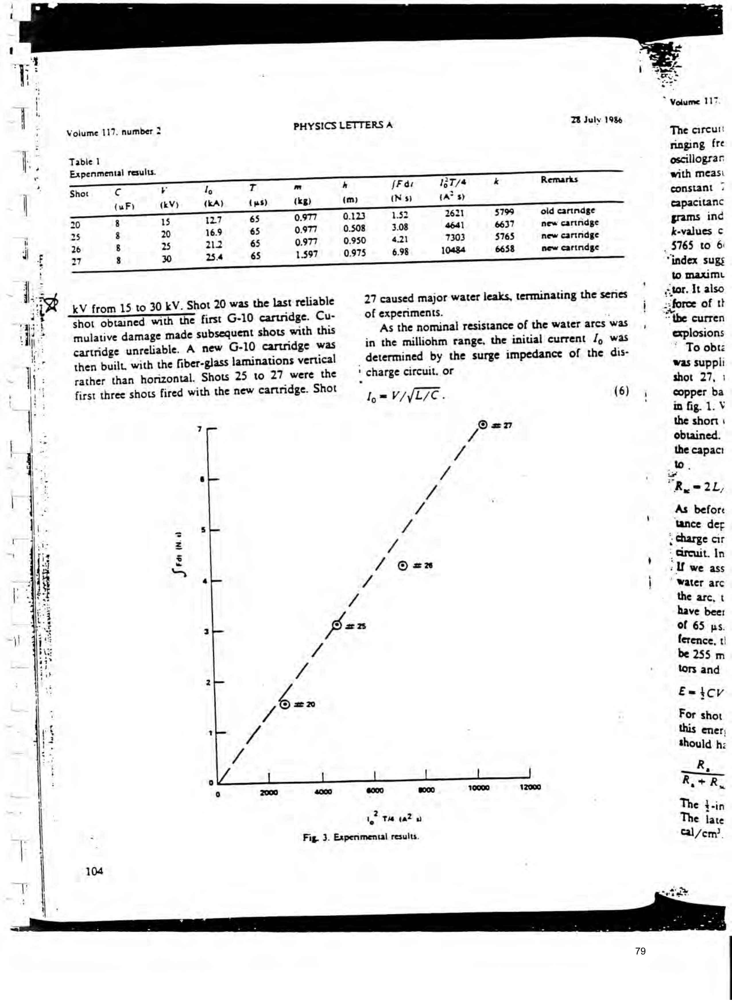
Out of a series of 27 capacitor discharges, the results of the four most important shots are listed In table 1 and plotted on fig. 3. All four shots involved the full 8 »F capacitance of the bank.
The charging voltage V was increased in steps of 5
SHUT ee hs TE be eee” et . Fs Oe ees oe . P a oe «te, BENS
:F Tel Te es
, any rer ery
Page 79
ih st tte 5 ns
Volume 117. number 2 PHYSICS LETTERS A ZB July 198 Table 1
Expenmental results.
Shot Cc r Ig T m [Fai 1377/4 k Remarks
kV from 15 to 30 kV. Shot 20 was the last reliable
Shot obtained with the first G-10 cartridge. Cumulative damage made subsequent shots with this cartridge unreliable. A new G-10 cartridge was then built, with the fiber-glass Jaminations vertical rather than honzontal. Shots 25 to 27 were the first three shots fired with the new cartridge. Shot
27 caused major water leaks, terminating the senes of experiments.
As the nominal resistance of the water arcs was in the milliohm range, the initial current /, was _ determined by the surge impedance of the dis- ' charge circuit. or
ween
sls /
Fig. 3. Experimental results.
~ Volume 117
The circu!!
ringing fre oscillograr with measi constant :
capacitanc grams inc
“index sugs to maxim ¢tor. It also
“the curren explosions * To obtz was suppli
copper ba in fig. 1. V the short | obtained.
the capac:
As befor:
tance der . Charge cir | Gireuit. In a we ass ‘Water arc the arc, t have beer
ference, ti
tors and
Extcv
For shot this ener;
should h:
The t-in
The iate
Cal /em).
Page 80
vere es * A 5) = aeoeig cee (ch Malice ates tie pele! 9 gta sh ber te bs inca hat il a ate
hoes re ‘ 4 eet Dal iaallitta d .
PU ‘ sat dm Odie wi email pinasAil tn ple Medea mdhoasitie) tna ak 8 eet ws as
Salume 117, number 2
The circuit selfinductance L was derived from the ringing frequency recorded on the current pulse oscillograms. I) calculated with eq. (6) agreed well with measurements of the Rogowski coil. The ume constant 7 did not vary with V so long as the capacitance C was kept constant. The oscillograms indicated a time constant of 65 ps. The j-values calculated for the four shots vary from 3765 to 6658. This nearly constant performance index suggested the apparatus was working close to maximum effectiveness as a projectile accelerator. It also provided evidence for the scaling of the force of the explosion with the action integral of the current pulse, as required for electrodynamic explosions.
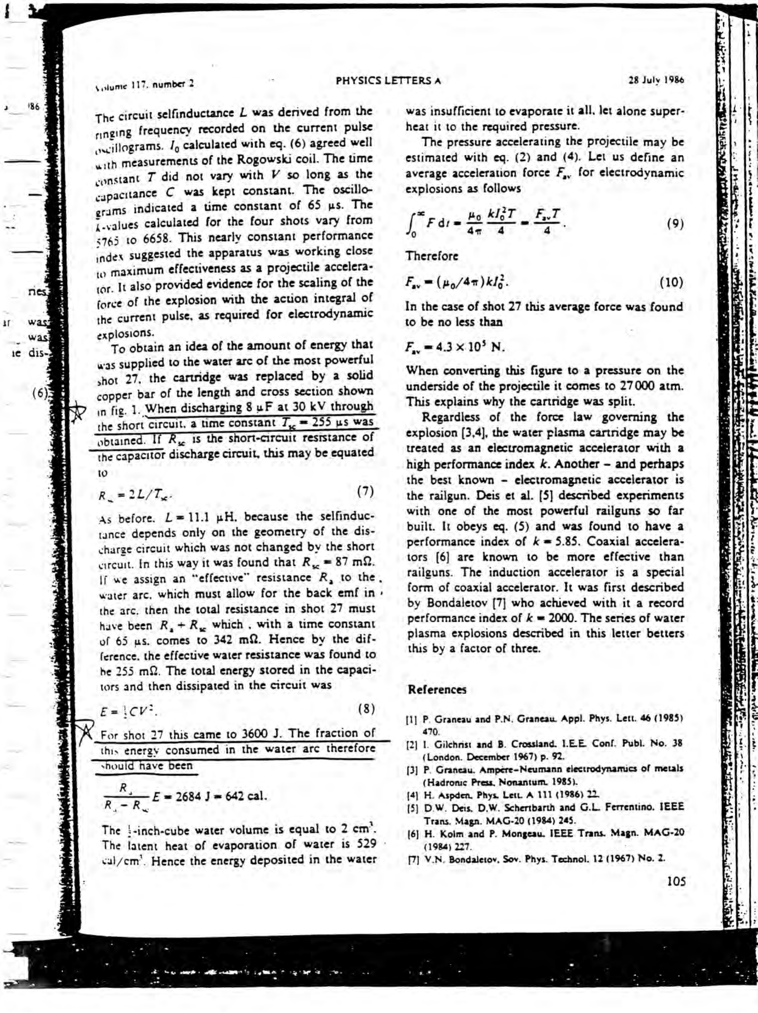
To obtain an idea of the amount of energy that was supplied to the water arc of the most powerful shot 27, the cartridge was replaced by a solid copper bar of the length and cross section shown in fig. 1. When discharging 8 uF at 30 kV through
the short circuit, a time constant i * 255 ws was
PHYSICS LETTERS A
nbtained. If Ry, is the short-circuit resrstance of
the capacitor discharge circuit, this may be equated
As before. L = 11.1 pH. because the selfinductance depends only on the geometry of the discharge circuit which was not changed by the short circuit. In this way it was found that Ry. = 87 mQ.
If we assign an “effective” resistance R, to the,
water arc, which must allow for the back emf in the arc. then the total resistance in shot 27 must have been R, + Ry. which , with a time constant of 65 us. comes to 342 mQ. Hence by the difference. the effective water resistance was found to he 255 mQ. The total energy stored in the capacitors and then dissipated in the circuit was
For shot 27 this came to 3600 J. The fraction of
this energy consumed in the water arc therefore
‘should nave been
The |-inch-cube water volume is equal to 2 em’.
The latent heat of evaporation of water is 529 -
cal/em’. Hence the energy deposited in the water
was insufficient to evaporate it all, let alone superheat it to the required pressure.
The pressure accelerating the projectile may be estimated with eq. (2) and (4). Let us define an average acceleration force F,, for electrodynamic explosions as follows
oa pg AIST F..T
[Cras Rae oe. (9)
Therefore
In the case of shot 27 this average force was found to be no less than
When converting this figure to a pressure on the underside of the projectile it comes to 27000 atm. This explains why the cartridge was split.
Regardless of the force law governing the explosion [3,4], the water plasma cartridge may be treated as an electromagnetic accelerator with a high performance index k. Another - and perhaps the best known - electromagnetic accelerator is the railgun. Deis et al. [5] described experiments with one of the most powerful railguns so far built. It obeys eq. (5) and was found to have a performance index of k = 5.85. Coaxial accelerators [6] are known to be more effective than railguns. The induction accelerator is a special form of coaxial accelerator. It was first described by Bondaletov [7] who achieved with it a record performance index of k = 2000. The series of water plasma explosions described in this letter betters this by a factor of three.
References
[1] P. Graneau and P.N. Graneau Appl. Phys. Lett. 46 (1985)
[2] 1. Gilehnst and B. Crossland. 1.LE Conf. Publ. No. 38 (London. December 1967) p. 92.
(3] P. Graneau. Ampere-Neumann electrodynamics of metals (Hadronic Press, Nonantum. 1985).
[5] D.W. Deis. D.W. Schertbarth and G.L. Ferrentino. IEEE
[6] H. Kolm and P. Mongeau. IEEE Trans. Magn. MAG-20
hitdeaae
weal G7
ane
ye heed On oe a ie ed
Provenance
- Pages
- pages 75–80 of 140
- Binder
- WFC Project Binder 423-DA
- Method
- pdftoppm 300dpi + tesseract 5 (eng), orientation-corrected
- Source
- WFC International Independent Test-Evaluation Report (1995), scanned binder
- Attribution
- Roy Azevedo, Peter Graneau, Charles Millet and Neal Graneau — Physics Letters A 117(2), 101–105 (1986)
- Reproduced material
- Reproduced inside Meyer's 1995 report as bound; copyright is the original author's.