report
Electrically induced explosions in water
3 August 1992
Page 71
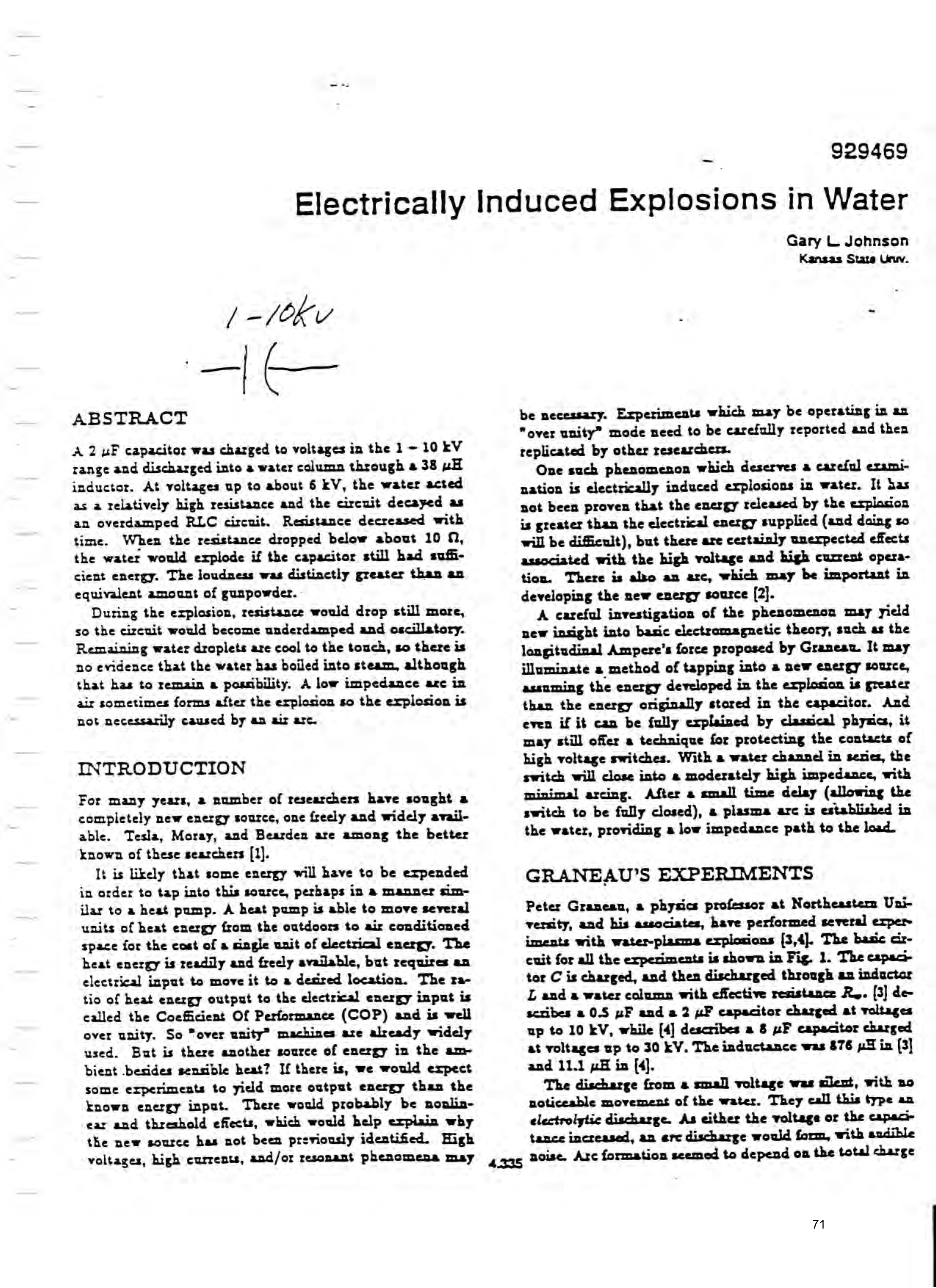
Electrically Induced Explosions in Water
ABSTRACT
A 2 uF capacitor was charged to voltages in the 1 - 10 kV range and discharged into a water column through a 38 «H inductor. At voltages up to about 6 EV, the water acted as a relatively high resistance and the circuit decayed as an overdamped RLC circuit. Resistance decreased with time. When the resistance dropped below about 10 0, the water would explode if the capacitor still had sufficient energy. The loudness was distinctly greater than an equivalent amount of gunpowder.
During the explosion, resistance would drop still more, so the circuit would become underdamped and oscillatory. Remaining water droplets are cool to the touch, so there is no evidence that the water bas boiled into steam, although that has to remain a possibility. A low impedance arc in air sometimes forms after the explosion so the explosion is not necessarily caused by an air arc.
INTRODUCTION
For many years, 2 number of researchers have sought a completely new energy source, one freely and widely available. Tesla, Moray, and Bearden are among the better known of these searchers [1].
It is likely that some energy will have to be expended in order to tap into this source, perhaps in a manner similar to a heat pump. A heat pump is able to move several units of heat energy from the outdoors to air conditioned space for the cost of a single unit of electrical energy. The heat energy is readily and freely available, but requires an electrical input to move it to a desired location. The ratio of heat energy output to the electrical energy input is called the Coefficient Of Performance (COP) and is well over unity. So “over unity” machines are already widely used. But is there another source of energy in the ambient .besides sensible heat? If there is, we would expect some experiments to yield more output energy than the known energy input. There would probably be nonlinear and threshold effects, which would help explain why the new source has not been previously identified. High
Gary L. Johnson
Kansas State Uruv.
be necessary. Experiments which may be operating in an "over unity” mode need to be carefully reported and then replicated by other researchers.
One such phenomenon which deserves a careful examination is electrically induced explosions in water. It bas not been proven that the energy released by the explasion is greater than the electrical energy supplied (and daing so will be difficnit), but there are certainly unexpected effects associated with the high voltage and high current operation. There is also an arc, which may be important in developing the new energy source [2].
A careful investigation of the phenomenon may yidd new insight into basic electromagnetic theory, such as the longitudinal Ampere’s force proposed by Graneau. It may illuminate a method of tapping into a new energy source, assuming the energy developed in the explosion is greater than the energy originally stored in the capacitor. And even if it can be fully explained by classical phyxic, it may still offer a technique for protecting the contacts of high voltage switches. With a water channel in series, the switch will close into a moderately high impedance, with minimal arcing. After a xmall time delay (allowing the switch to be fully closed), a plasma arc is established in the water, providing a low impedance path to the load.
GRANEAU’S EXPERIMENTS
Peter Graneanu, a physics professor at Northeastern University, and his associates, have performed several exper iments with water-plasma explosions [3,4]. The basic circuit for all the experiments is shown in Fig. 1. The cepacitor C is charged, and then discharged through an inductor L and a water column with effective resistance R,. [3] describes a 0.5 uF and a 2 uF capacitor charged at voltages up to 10 kV, while [4] describes a 8 uF capacitor charged at voltages up to 30 KV. The inductance was 876 pO in (3]
The discharge from « small voltage was silent, with no noticeable movement of the water. They call this type an electrolytic discharge. As either the voltage or the capac tance increased, an are discharge would form, with audible
voltages, high currents, and/or resonant phenomena may 4 a1 noise. Arc formation seemed to depend on the total charge
Page 72
Siag through the water. A float above the arc would be
sed upward, but the impulse seemed to terminate with
c. No followthrough push from expanding steam nor vy-wapor escape from the water could be discerned.
Figure 1: Water Arc Discharge Circuit
In two cases with the same stored energy, 2 0.5 uC caa~+or charged to 6 EV and a 2 uC capacitor charged to the second case resulted in an arc explosion while
first did not. In both cases, the heat dissipated in the a*-- was less than one calorie, in a container of about 120 of water. Their conclusion, based on measurement, culation, and visual observation, was that the explosion a- ~ot based on thermal effects. They conclude, rather, . he explosion was due to longitudinal Ampere forces. \s concept of a tension force in a single conductor due to
- “nrrent flow in the conductor is not taught in introduc- 1 lectromagnetic theory courses, but Graneau makes a
rd case for such longitudinal forces in [5].
Mhey discovered that tap water produced explosions b twice as strong as those in saturated saltwater. The rnilosions in distilled water were even stronger, except
tit was difficult to initiate the arc in distilled water.
: calculated pressure in the chamber in the last test in
\] was 27000 atm. Their comment was “This explains why
cartridge was split.” They defined a figure of merit as
rength of the explosion per unit action integral of the
vrrent pulse, and found that the figure of merit for their
“tem was three times as high as the very best railgun
mance. Railguns have better acceleration character-
sics than chemical explosives, so water arcs have more
sang per buck” than any other explosive, save perhaps
vater arcs are therefore interesting to study. At a mintum, they would indicate that Ampere's force law needs
re a longitudinal component. It is conceivable, how-
tr, that careful experimental studies will show that the otal energy emitted from the explosion is greater than the 2) electrical energy. This would certainly support the veept that the vacuum has a high energy density and
t we might be able to extract some of this energy with o ght equipment.
. ‘ME WORKSHOP EXPERIMENT
‘~ well equipped high energy laboratory was available, so ras decided to replicate as much as possible of Graneau’s ‘| ate experiments in a home workshop. The water columm length and diameter would be varied and any instruntation problems would be noted. No attempt would be
made to do any calorimetry measurements. These are far beyond the capability of this particular home workshop.
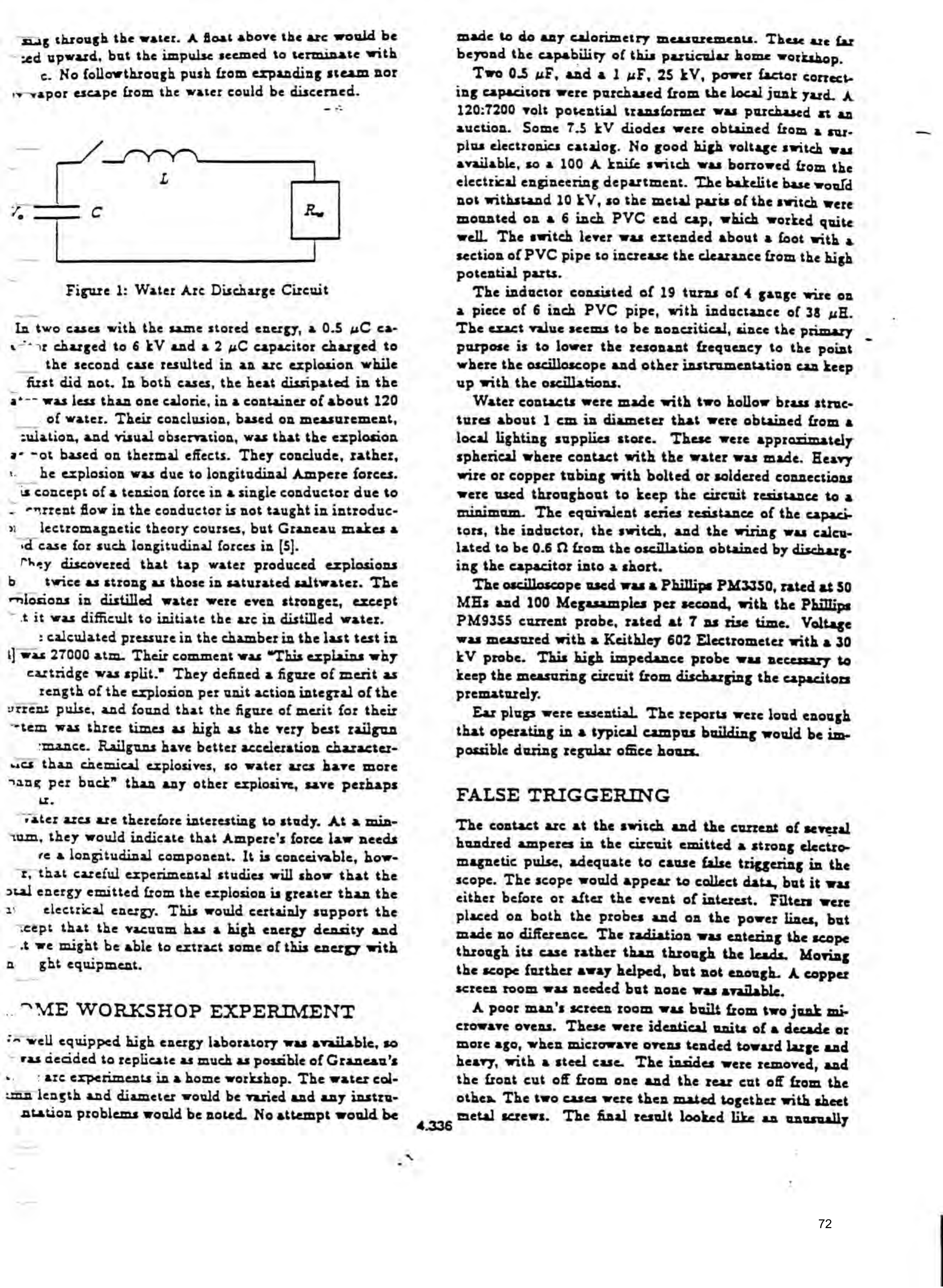
Two 05 uF, anda] uF, 25 kV, power factor correct. ing Capacitors were purchased from the local junk yard. A 120:7200 volt potential transformer was purchased at an auction. Some 7.5 kV diodes were obtained from a guyplus electronics catalog. No good high voltage switch was available, so a 100 A knife switch was borrowed from the electrical engineering department. The bakelite base would not withstand 10 kV, so the metal parts of the switch were mounted on a 6 inch PVC end cap, which worked quite well. The switch lever was extended about a foot with a section of PVC pipe to increase the clearance from the high potential parts.
The inductor consisted of 19 turns of 4 gauge wire on a piece of 6 inch PVC pipe, with inductance of 38 uH. The exact value seems to be noncritical, since the primary purpose is to lower the resonant frequency to the point where the oscilloscope and other instrumentation can keep up with the oscillations.
Water contacts were made with two hollow brass structures about 1 cm in diameter that were obtained from a local lighting supplies store. These were approximately spherical where contact with the water was made. Heavy wire or copper tubing with bolted or soldered connections were used throughout to keep the circuit resistance to a minimum. The equivalent series resistance of the capaci tors, the inductor, the switch, and the wiring was calculated to be 0.6 M from the oscillation obtained by discharging the capacitor into a short.
The oscilloscope used was a Phillips PM3J50, rated at 50 MHz and 100 Megasamples per second, with the Phillips PM935S5 current probe, rated at 7 ns rise time. Voltage was measured with a Keithley 602 Electrometer with a 30 kV probe. This high impedance probe was necessary to keep the measuring circuit from discharging the capacitors prematurely.
Ear plugs were essential The reports were loud enough that operating in a typical campus building would be impossible during regular office hours.
FALSE TRIGGERING
The contact arc at the switch and the current of several hundred amperes in the circuit emitted a strong electro magnetic pulse, adequate to cause false triggering in the scope. The scope would appear to collect data, but it was either before or after the event of interest. Filters were placed on both the probes and on the power lines, but made no difference. The radiation was entering the scope through its case rather than through the leads. Moving the scope further away helped, but not enough. A copper screen room was needed but none was available.
A poor man's screen room was built from two junk microwave ovens. These were identical units of a decade or more ago, when microwave ovens tended toward large and heary, with a steel case. The insides were removed, and the front cut off from one and the rear cut off from the othes The two cases were then mated together with sheet metal screws. The final result looked like an unusually
Page 73
deep microwave oven, complete with the door in working order. The scope would easily fit inside. “A power line filter was added where the power cord entered the modified oven, The signal was brought in by a small 50 N coaxial cable through a small hole. The scope would be armed to collect data, the door closed, and then the knife switch closed. The door would then be opened and the trace examined. This technique eliminated the false triggering up to the limits of the experiment, approximately 10 kV and
CURRENT PROBE
The Phillips PM9355 current probe is only rated to about 4 A peak, so some method of current division had to be used. The manufacturer suggested placing several identical wires in parallel, and measuring the current in one of the wires. This technique did not work because the probe would insert additional impedance into the wire being measured, causing the current to divide unequally. This effect is called the burden of the meter.
The solution was to put a 0.1 9, 10 W resistor in series with the water are. A 50 © coaxial cable was connected across the resistor. The other end of the cable was terminated with a 50 M resistor inside the oven. Current through this resistor was then measured with the PM9355 probe. The 0.1 @ resistor was placed inside an aluminum box to reduce the transient electric field effects. The burden of the probe was small compared with 50 1 so this technique worked rather weil.
WATER COLUMN
Three different sizes of plastic tubing were obtained, with nominal inside dimensions of 1/8, 5/32, and 7/32 inches. These were cut in lengths of 1 and 2cm. The tube was filled with saturated salt water or tap water and placed in a horizontal position between the two electrodes. Surface tension of the water was usually adequate to keep the water in place in an otherwise dry and clean piece of tubing. The electrodes were held in place by the stiffness of a few inches of 4 gauge copper wire. That is, the electrodes were free to move when an explosion occurred. For some tests, the electrodes were held to the tubing with large rubber bands. This would help keep the tubing in place for small water ares, but seemed to have little difference on the results.
RESULTS
Preliminary tests were performed with 1 uF of capacitance and voltages up to 10 kV, on the shortest and thinnest piece of tubing. At voltages up to 7 or 8 EV, there would be little or no sound, but the water may be blown out of the tubing. At 9 kV there was a small “pop” part of the time. At 10 kV there was a larger pop, similar to « small firecracker. Tap water may have been slightly louder than salt water, but certainly not much. Low resistance arcs were bard to establish, so all the remainder of the tests were performed with 2 uF of capacitance.
The circuit acts as an overdamped RLC circuit when the resistance of the water column is greater than about 3 0. The water resistance decreases with time and with the applied voitage, making it difficult to present specific values with broad application. Examples would be the 7/32 inch ID by 1 em long tubing which had a resistance of 27M at 6 kV and 17 Mat 10 EV, at 10 us after switching, and the 5/32 inch by 1 cm long tubing which had a resistance of 55 M at 6 KV and 32 M at 10 EV, also 10 us after switching. Only if a low impedance arc forms will the resistance drop below 3 M and the current become oscillatory. This takes time to develop and will not occur consistently even for apparently identical conditions. ;
For example, compare two consecutive tries at 10 EV on the 1/8 inch ID by 2 cm long tubing. Both produced a loud bang, similar in loudness. In the first try, the current was 50 A at 5 us after switch closing, 80 A at 50 ps, a peak of 130 A at 130 us, and went to sero at 153 ys. In the second try, the current was 24 A at 5 us, 72 A at 50 ps, and went to sero at 166 us. At 138 us, however, an arc was apparently initiated, so there was what appeared to be a half cycle of an underdamped wave between 138 and 166 us. The peak current of this half cycle was 540 A.
Longitudinal Ampere forces vary as the square of the current, so if the explosion is due to these forces we would expect a significant difference in loudness. Since little or no difference was noted in the explosion, there remains a question whether the longitudinal Ampere forces are eves a major cause of the explosion.
Another observation was that of small bubbles forming in the tubing, with no arc and no noise. At 6 EV,a 7/32 inch by 1 cm piece of tubing would show a very small (less than 1 mm diameter) bubble. At 8 KV, the same tubing would show a bubble about 2 mm in diameter. The presence of a bubble will lower the arc inception voltage. That is, with the bubble in place, the next firing at 8 kV may be adequate to cause an arc with an oscillating waveform. Increasing the capacitance also lowers the arc inception voltage.
Loudness was found to be inversely proportional to the tubing area. The loudest reports were from the 1/8 inch ID tubing. Changing from salt water to tap water did not make nearly as great a difference
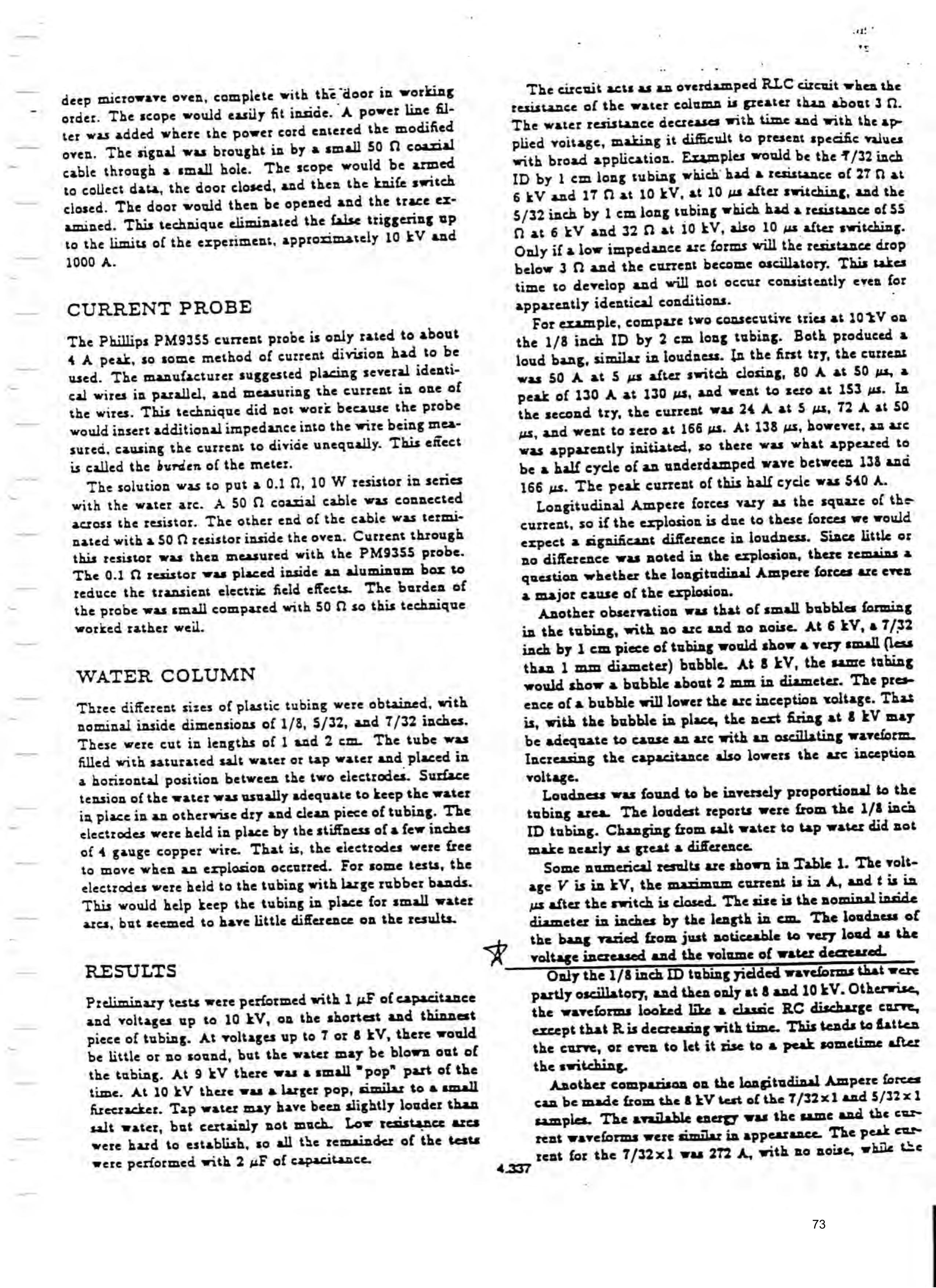
Some numerical results are shown in Table 1. The voltage V is in EV, the maximum current is in A, and ¢ is in ps after the switch is closed. The size is the nominal inside diameter im inches by the length in em. The loudness of the bang varied from just noticeable to very load as the voltage increased and the volume of water decreared.
—Gnaly the 1/8 inch ID tubing yidlded wavelorms that were partly oscillatory, and then only at 8 and 10 kV. Otherwise, the waveforms looked like a classic RC discharge curve, except that Ris decreasing with time. This tends to flatten the curve, or even to let it rise to a peak sometime after the switching.
Another comparison on the longitudinal Ampere forces can be made from the 8 EV test of the 7/32x1 and 5/32x1 samples. The available energy was the same and the cur rent waveforms were similar in appearance. The peak cam rent for the 7/32x1 was 272 A, with no noise, while the
Page 74
; twrent for the $/22 x1 was 195 A, wnico produced @ sa pop. The czrrent density for the smaller tubing was sat 40 % greater than for the larger tubine, so perhaps
at density is more important to a water explosion
jan the actual current.>-
TABLE 1
Maximum Current and Time to Maximum
Vv size teas t bang?
ICLUSIONS
ectrically induced explosions in water are relatively easy iduce with a 2 uF capacitor charged to 10 kV. Exag steam does not seem to be the main cause. Similar vlosions are obtained with significantly different peak "ts, which raises questions about the longitudinal re forces being the primary cause. It is therefore aceivable that we are tapping a new energy source. “te experiments need to be performed to demonstrate ae way or the other. A better screen room, larger ca- -tors, and a better high voltage switch would be helpful weriety of electrode and water channel configurations 10 be tested to separate out the effects of water arcs water explosions. A calorimeter test would be interime, A microphone pickup to electronically determine ss would be useful.
f course, even if water explosions are tapping into a - energy source, this technique may not be the optimum ) extract this energy. But it could lead us toward « ex understanding of this source.
ohnson, Gary L., “Searchers for a New Energy Source la, Moray, and Bearden”, IEEE Power Engineering
2. Hathaway, George D., “Zero-Point Energy: A New Prime Mover? Energy Requirements for Energy Productien & Propulsion from Vacuum Fluctuations", Proceed. tugs of the IECEC, 1991.
3. Graneau, Peter and P. Neal Graneau, “Electrodynamic Explosions in Liquids", Applied Physics Letters, Vol.
4. Azevedo, Roy, Peter Granean, and Charles Millet, “Powerful Water—Plasma Explosions, Physics Letters A,
5. Graneau, Peter, Ampere-Neumann Electrodynamics of Metals, Hadronic Press, Nonantum, Mass. 02195, 1945.
ComOITON WHEN (CB Pac ten
(S Rurty QW PEGE APPLING ANE =
HIGHEST Verbece WwTiEVVIAN ZF ei. TPE
GRROSITR Parkry GF yatt
q7TaNoNy ACkayS 54O wepee~oaP
ELE CHCY CLUSTHAUM: 770 Uns
Whe) SPID CAPACITCN iS WU WR
Pity -CW ARGH STATE,
Provenance
- Pages
- pages 71–74 of 140
- Binder
- WFC Project Binder 423-DA
- Method
- pdftoppm 300dpi + tesseract 5 (eng), orientation-corrected
- Source
- WFC International Independent Test-Evaluation Report (1995), scanned binder
- Attribution
- Gary L. Johnson, Kansas State University — SAE Technical Paper 929469 (1992)
- Reproduced material
- Reproduced inside Meyer's 1995 report as bound; copyright is the original author's.