Pulsing a coil with a cap pulser
Started by John_Koorn · · 59 posts · last reply 1 June 2018
-
#26 ·
Faraday, you don't have to do it exactly the way I am. Think about it - in it's simplest form it's a 3 battery switch that pulses a coil and then captures the spike into the third battery.Faraday88 wrote:
JK,
Thanks for that little help! however, your schematic earlier shows the primary coil in series with the charge battery while the secondary is 'kind of parallel' via the conversion in FWBR.
Since i do not have the Large Comparator... I would in essence have the Capacitor Discharge through a SCR or a MOSFET,(Transistors will not survive for sure) the SCR would Self commutate due to Series Resonance action but with this startegy you cannot make the 'bell ring twice' so Dual MOSFET is the best bet. BTW this is true even with Battery based primary switching..a cousin of the SSG.
just my way of tinkering...
thank s again... lets experiment..
Rgds,
Faraday88.
You could do the switching easily with 1 transistor and a 555 timer. Would cost about 50 cents in parts to do that.
John K. -
#27 ·
Hi JK,John_Koorn wrote:
Faraday, you don't have to do it exactly the way I am. Think about it - in it's simplest form it's a 3 battery switch that pulses a coil and then captures the spike into the third battery.
You could do the switching easily with 1 transistor and a 555 timer. Would cost about 50 cents in parts to do that.
John K.
If it is BJT (Bipolar Junction transistor) MJE15024 should be ok...hmmmm..
one transistor and Ringing it twice...ok !
Rgds,
Faraday88. -
#28 ·
Hi Richard,Richard wrote:
I appreciate your knowledgeable comments here, John.
Would you be so kind as to make a quickie schematic of such circuit including battery voltage and amp hours and also coil number of turns, wire gauge and type of core, air or iron, nothing exact, just off the top of your head approximate numbers?
A 12 volt 100 amp hour battery would be a good example but I can scale up or down from whatever you choose.
555 timer circuits are plentiful so if you can just "black box" diagram that part and show the frequency.
Thanks.
Here's a simple schematic. I'm not going to list component details, that's up to you guys to experiment with. The batteries you're planning on using will determine the size of the coil, the transistor, etc., etc.
Simple 3 Batt Switch.pdf
This is about as easy as I can make it. -
#29 ·
Faraday,Faraday88 wrote:
Hi JK,
If it is BJT (Bipolar Junction transistor) MJE15024 should be ok...hmmmm..
one transistor and Ringing it twice...ok !
Rgds,
Faraday88.
I have absolutely no idea what "ring the bell twice" means. If you want to paraphrase that quote to suit this set up, knock yourself out. I'd rather use "really efficient battery charger".
John K. -
#30 ·
JK,John_Koorn wrote:
Faraday,
I have absolutely no idea what "ring the bell twice" means. If you want to paraphrase that quote to suit this set up, knock yourself out. I'd rather use "really efficient battery charger".
John K.
'Tesla Impulse Technology'...thats all I too meant.. It was my contension to try the experiment to acheive the same thing without the access to the Large Comparator! in my opinion the Comparator is already doing the TIT part, with the circuit you showed, it does another level of amplification of the gain in the connected battery.
Best Regards,
Faraday88. -
#31 ·
Hi Richard,Richard wrote:
Thank you, John.
Very helpful.
Your schematic does not show the gist of what JK is wanting us to experiment with..
remember its the Capacitor-Discharge into an Inductance coil...and capturing the reaction spike of this Radiant Energy.
but there is nothing wrong in the way it is shown(your schematic)...no doubt it works.. you need to have specific duty cycle to the switching you have there using 555 pusle generator.
Best Regards,
Faraday88. -
#32 ·
Here's a quick video I shot earlier today:
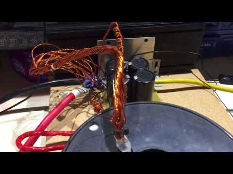
Richard, you are right - air core and fast diodes. I have UF5408 in the FWBR but I should put faster ones in. I don't have the extra diode because I'm using the cap pulser. But if you are going to use 2 batteries in series in place of a cap pulser you'll need it.
I did try R60 rod core, but the charging wasn't as good as with the air core.
After I shot this video I did mount the solar panel on the roof. Got a few minutes of late afternoon sun in between the clouds, where I was getting just under 3A from the solar panel
If you have #18, I'd go with that. ~130' will be 3 ohms per winding IIRC. Make the coil as big as you can if you've got a 100Ah battery. Just wind all the strands together and twist them to keep it tidy.
John K. -
#33 ·
Hi JK,John_Koorn wrote:
Here's a quick video I shot earlier today:
Richard, you are right - air core and fast diodes. I have UF5408 in the FWBR but I should put faster ones in. I don't have the extra diode because I'm using the cap pulser. But if you are going to use 2 batteries in series in place of a cap pulser you'll need it.
I did try R60 rod core, but the charging wasn't as good as with the air core.
After I shot this video I did mount the solar panel on the roof. Got a few minutes of late afternoon sun in between the clouds, where I was getting just under 3A from the solar panel
If you have #18, I'd go with that. ~130' will be 3 ohms per winding IIRC. Make the coil as big as you can if you've got a 100Ah battery. Just wind all the strands together and twist them to keep it tidy.
John K.
Great video and thanks !
Yes, Power Schottky Diodes http://www.st.com/resource/en/datash...ps30l30djf.pdf
for the Bridge must just be the gift for this circuit!
some interiguing questions though....[U]the Series- Resonant frequency of the dump is high when it is Air cored.[/U].. should that be the only reason for the lower performance with a ferromagnetic core(R60)?
Rgds,
Faraday88 -
#34 ·
Hi Richard,Richard wrote:
Faraday, that is JK's schematic, not mine.
I hope he will respond to your comment.
It looks to me like the battery is "capturing the reaction spike of this Radiant Energy" rather than a cap. I would think the FWBR should be high speed diodes as well as that other diode.
I would also like to know the best gauge wire to use in the coil for 100 amp hour batteries and the number of primary and secondary turns. I have a good supply of #10 square, #18 and #26. Should it be wound bifilar or with one winding first and the second winding over the first winding? I presume an air core.
Please feel free to post a schematic of your own. Any added notes as to what results you got from the circuit would be helpful.
Richard
Here is a schematic i would like to share and as a food for thought..
It is basically a Vanilla coil to study the reaction of the coil to a Capacitor dump and how you can catch the Radiant at different Tesla nodes!
Rgds,
Faraday88. -
#35 ·
Hi Faraday,
Not sure that circuit will work. Looks like the diodes in the FWBR are drawn wrong.
Have you built the basic version that I posted? Not sure why your innovating before replicating????
John K. -
#36 ·
Hi JK,John_Koorn wrote:
Hi Faraday,
Not sure that circuit will work. Looks like the diodes in the FWBR are drawn wrong.
Have you built the basic version that I posted? Not sure why your innovating before replicating????
John K.
Thank you for your wise inputs as always! Yes, not yet tried your version.. just intriguing on the coil geometry , turns ratio, gauge, with respect to the standard Switched Battery (SSG) mode ect. about the FWBR orientation,I just worked out the other possible configuration for this topology... it seems to short the Switch either ways.. so i stick with the above schematic. must be doing something to the receive battery for sure.
Best Regards,
Faraday88. -
#37 ·
So, has no one else tried this yet?
Here's a pic of a charge monitor for today. Note that today was cloudy all day, only a couple of small periods of sunlight. This is real world data, not made up. Here is a free energy machine, COP of infinity.
Graph starts at 6:15AM and ends at around 7:00PM
One day soon I'll get a sunny day
John K.Attached Files -
-
#38 ·
Hi JK,John_Koorn wrote:
So, has no one else tried this yet?
Here's a pic of a charge monitor for today. Note that today was cloudy all day, only a couple of small periods of sunlight. This is real world data, not made up. Here is a free energy machine, COP of infinity.
Graph starts at 6:15AM and ends at around 7:00PM
One day soon I'll get a sunny day
John K.
Infinity COP for the sunlight falling on the panels... that is known already! what do you what to show by those the scope shots ? its a CBAIII software plot..
rgds,
Faraday88. -
#39 ·
Hi Faraday,Faraday88 wrote:
Hi JK,
Infinity COP for the sunlight falling on the panels... that is known already! what do you what to show by those the scope shots ? its a CBAIII software plot..
rgds,
Faraday88.
The plot is showing that even on a cloudy and rainy day this setup is charging the battery a lot more than if you were to just hook the solar panel up directly to the battery.
John K. -
#40 ·
Hi JK,John_Koorn wrote:
Hi Faraday,
The plot is showing that even on a cloudy and rainy day this setup is charging the battery a lot more than if you were to just hook the solar panel up directly to the battery.
John K.
Agreed..but then the plot doe'snt show when there is sunlight(or wind flow) or not corresponding to the plot reading..how do we asses that??
Is this using your Pulser circuit with the Comparator?
Rgds,
Faraday88. -
#41 ·
Hi Faraday,
Well, the plot does show a couple of periods where the charging is higher than the rest of the plot. Between roughly 250 and 350 minutes (about midday) you can see the voltage fluctuates between 13.0 and 13.6.
Yes, this is using the setup as shown in the video.
John K. -
#42 ·
Hi Richard,Richard wrote:
On your video posted 5-13-18 I get only a black square and does nothing when I click on it. Does anyone else have a problem viewing it?
I was able to view the video with no problem what so ever!

Rgds,
Faraday88. -
#43 ·
-
#44 ·
@all,Faraday88 wrote:
Hi JK,
Thank you for your wise inputs as always! Yes, not yet tried your version.. just intriguing on the coil geometry , turns ratio, gauge, with respect to the standard Switched Battery (SSG) mode ect. about the FWBR orientation,I just worked out the other possible configuration for this topology... it seems to short the Switch either ways.. so i stick with the above schematic. must be doing something to the receive battery for sure.
Best Regards,
Faraday88.
Here is my latest circuit... I would like to emphasis one thing in perticular to this topology though.. the input parameters such as the Capacitors, the Coil and the some other things have to of the following specification:
1) High Voltage/Low capacitance Capacitor you can use the output of a SSG machine to charge this.
2) Coil bifilar Air-cored
3) High-impedance light bulb (High-Voltage/low current)
4)The FWBR has to be a High-Voltage Fast recovery type (descrete assembled), also the Diode on the positive line above 'feeding' the light bulb(Electron extraction element of Stanley Meyer) .
.
@All,
Just wanted to post a corrected Circuit..here below is the corrected circuit: the Battery(Polarization) alignment to the Radiant spike is corrected please note.
Best Regards,
Faraday88.Attached Files -
-
#45 ·
Hi Faraday,Faraday88 wrote:
@all,
Here is my latest circuit... I would like to emphasis one thing in perticular to this topology though.. the input parameters such as the Capacitors, the Coil and the some other things have to of the following specification:
1) High Voltage/Low capacitance Capacitor you can use the output of a SSG machine to charge this.
2) Coil bifilar Air-cored
3) High-impedance light bulb (High-Voltage/low current)
4)The FWBR has to be a High-Voltage Fast recovery type (descrete assembled), also the Diode on the positive line above 'feeding' the light bulb(Electron extraction element of Stanley Meyer).
Best Regards,
Faraday88.
can you please explain how your circuit is pulsing the coil with a cap pulser? (as per the thread title)
John K. -
#46 ·
Graph showing pulsing the coil reduces charge time with same input
I wanted to prove whether or not pulsing a coil with a cap pulser was providing any extra benefit, rather than just directly charging a battery with a cap pulser.
Here's a charge chart that shows that pulsing a coil with the Bedini Large Comparator reduces the charge time with the same input.
The black charge curve is displaying the battery being charged with just the output of the Bedini Large Comparator (BLC). The input to the BLC is a lab power supply that has the current set at 2.0A. The BLC is set to discharge the capacitors at 25V.
The red charge curve is displaying the battery being charged with the BLC and the coil, as per the previously posted schematic. The input to the BLC is a lab power supply that has the current set at 2.0A. The BLC is set to discharge the capacitors at 25V.
As you can see by the below chart, the battery was completely charged about 1 hour faster by pulsing the coil with the cap pulser, as opposed to charging it directly with the cap pulser.
Below is an enlarged part of the last part of the black charge curve, showing the battery was charged to 15.409V in 1,299 minutes.
Below is an enlarged part of the last part of the red charge curve, showing the battery was charged to 15.429V in 1,243 minutes - a slightly higher voltage in 56 minutes less.
This a approximately a 5% reduction in charge time.Attached Files -
-
#47 ·
Hi JK,John_Koorn wrote:
Hi Faraday,
can you please explain how your circuit is pulsing the coil with a cap pulser? (as per the thread title)
John K.
I did not have access to the cap pulser ( Large Comparator), but that did not stop me from trying out this version of the circuit.
The power switch i will leave it for people here in the forum to tinker with. i know it can be done with several ways present in all bedini books (FEG as well).
I have hinted enough on the parameters essential to this topology..especially the High-Voltage, Low Capacitance for a Air-cored Coil that you showed us.
i want people to understand the gist of the process more than just build it and leave it.. Science behind this is paramount.. its 'Use' only reaps as a blessing to individuals.
How the circuit works: this circuit is inverted version of the standard SSG/SG circuit.
but its the full regaugue version of it with the use of the Light bulb used in that position.
Look at the resistor/light bulb, as i said its exact opposite of the battery..ie a battery is a Negistor and the a light buld is a Resistor.. in the Gauge -regauge mechanism process(Tesla-Impulse-Reaction) the resistor becomes more resistive and the negistor becomes more Negative and that is where it is the same as the Electron-extrator like what Stan Meyer does in further boosting the Energy level by Ionizing HHO gas (ie. the Gas atoms get highly charged and the electrons ripped off and sent into the resistor getting 'consumed' there as Power.
Best Regards,
Faraday88. -
#48 ·
Super JK!!John_Koorn wrote:
I wanted to prove whether or not pulsing a coil with a cap pulser was providing any extra benefit, rather than just directly charging a battery with a cap pulser.
Here's a charge chart that shows that pulsing a coil with the Bedini Large Comparator reduces the charge time with the same input.
The black charge curve is displaying the battery being charged with just the output of the Bedini Large Comparator (BLC). The input to the BLC is a lab power supply that has the current set at 2.0A. The BLC is set to discharge the capacitors at 25V.
The red charge curve is displaying the battery being charged with the BLC and the coil, as per the previously posted schematic. The input to the BLC is a lab power supply that has the current set at 2.0A. The BLC is set to discharge the capacitors at 25V.
As you can see by the below chart, the battery was completely charged about 1 hour faster by pulsing the coil with the cap pulser, as opposed to charging it directly with the cap pulser.
Below is an enlarged part of the last part of the black charge curve, showing the battery was charged to 15.409V in 1,299 minutes.
Below is an enlarged part of the last part of the red charge curve, showing the battery was charged to 15.429V in 1,243 minutes - a slightly higher voltage in 56 minutes less.
This a approximately a 5% reduction in charge time.
Plus the Depth of Charge in the Battery that happens by this method..
I guess with cycling on this Charger it will increasingly get better and then stabilize at a point
Best Regards,
Faraday88. -
#49 ·
I did say in an earlier post that you don't need a Bedini Large Comparator to try this circuit. In fact, I said you could build it with 2 12V batteries and a $1 555 timer circuit in about 20 minutes. Remember, the basis of the experiment is a "3 battery switch"??Faraday88 wrote:
Hi JK,
I did not have access to the cap pulser ( Large Comparator), but that did not stop me from trying out this version of the circuit.
The power switch i will leave it for people here in the forum to tinker with. i know it can be done with several ways present in all bedini books (FEG as well).
I have hinted enough on the parameters essential to this topology..especially the High-Voltage, Low Capacitance for a Air-cored Coil that you showed us.
i want people to understand the gist of the process more than just build it and leave it.. Science behind this is paramount.. its 'Use' only reaps as a blessing to individuals.
How the circuit works: this circuit is inverted version of the standard SSG/SG circuit.
but its the full regaugue version of it with the use of the Light bulb used in that position.
Look at the resistor/light bulb, as i said its exact opposite of the battery..ie a battery is a Negistor and the a light buld is a Resistor.. in the Gauge -regauge mechanism process(Tesla-Impulse-Reaction) the resistor becomes more resistive and the negistor becomes more Negative and that is where it is the same as the Electron-extrator like what Stan Meyer does in further boosting the Energy level by Ionizing HHO gas (ie. the Gas atoms get highly charged and the electrons ripped off and sent into the resistor getting 'consumed' there as Power.
Best Regards,
Faraday88.
I'm not going to hold you back from whatever experiments you want to do (in fact I encourage it!), however I do consider that your circuit is so far removed from mine that you should've started a separate thread.
John K. -
#50 ·
Thank youFaraday88 wrote:
Super JK!!
Plus the Depth of Charge in the Battery that happens by this method..
I guess with cycling on this Charger it will increasingly get better and then stabilize at a point
Best Regards,
Faraday88.
Yes, I did theorise to myself that this method of charging should provide a deeper charge and improved rejuvenation capabilities, however I have not done enough testing to prove that theory yet.
Anyhow, I did design this primarily as a practical "solar charger" so the next step is to design a circuit that will stop charging when the battery is fully charged.
After that I'm going to revisit my 3 battery switch circuit that rotates the batteries when required, but still using the "pulsing the coil" method that is the topic of this thread. The end goal is the "self-running" battery charger - still chasing that dream
John K.