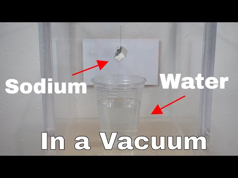
Hello Aaron, it's cool that you replied! I would like to clarify for you that i am not apart of the research team or nor-did i make the posted video. I am posting them to stimulate thought and conversation. However i am currently building the RF power source, i have the frequency generator and will be experimenting with the set-up presented in the research paper. My idea is however to use a cationic membrane based water reservoir with a NaCl electrolyte on one side and a NaOH electrolyte on the other, or kCl and KOH respectively. In theory that should minimize the glow discharge of sodium ion's reacting with water and hydrogen gas at the "pinch" point, which would allow the device to liberate chlorine gas and use it as an "oxidant" as a working gas.
tree Of Meraki
23 posts · 16 threads started · 27 more in threads this archive does not carry · writing between Sep 2018 and Oct 2018
An identity on Energy Science Forum as it was harvested, not an account on this site. Nobody here has claimed it, and nothing connects it to a person by name.
Hello, i would like to clarify that the video and research are not mine and i have no place in them except for that i am interested in the chemistry and the feasibility of Radio-frequency induced dissociation and further usage of a chlorine-hydrogen fuel. The research link is to stimulate conversation and thought about the concepts. Correct, @Faraday88, had this video used a UV led as well it would have been more conclusive, however the reaction between H-CL is very well known and very "old" chemistry.
The alloy activation chamber in progress of being constructed. These pictures are mock ups of the potential valve configurations for best functionality, but with safety in mind (as this will operating at 8bar) The pressure release is set to 12 bar, a 16b pressure gauge will be placed at the elbow point (not shown as it hasn't arrived in the mail yet) and the two valve connections are specific, one for hydrogen, and one for Argon, with a gas exit valve at the bottom of the chamber.
What will happen in this device is the Hydrogenation of the target metal alloy (see my earlier posts for image of alloy) the alloy will be exposed to heat and hydrogen gas under pressure which will pulverize the metal in an extremely fine mesh with hydrogen bound to the metal lattice as a Metal-hydride crystal. The powdered metal will then be ball milled with conductive carbon and graphite powders and then made into an electrode with conductive polymer binder This is the first step in creating the electrode active material, activation of the metal alloy via hydrogenation reaction.
I haven't weighed it. It's an atmosphered controlled thermal reactor or hydrothermal reactor. Just a reaction vessel.
There will be a gravity based escape valve and a connection to a vacuum pump.
I also have attempted "ORMUS" using non-alkaline states of high dielectric pressure as well, i used a 24,000V tesla coil and maltodextrin though so it wasn't truly monatomic, just angstrom colloidal. Brilliant purple colour, but not much i could do with it hahaha. I must add i was using 99.99% gold wire as well.
I've read reference to cooper-pairs as "special state matter" before.
Thank you, Gary. Your reply is appreciated.
I am wondering, from the Stanley Meyer's fans that will see this, or those who know. If i am using coaxial (cocentric) tubes as the electrolysis electrodes, the harmonic oscillation of the waveform between the electrodes is slightly variable, but generally a set frequency range for the dimensions of the electrodes. But if i use instead a slightly recursive spiraling pattern to the electrode geometry, so parallel plates that are separated but spiraled similar to "jelly roll" 18650 cells. This would increase the active surface area while decrease total reaction volume in space. However, would the variable distance between the electrodes at different points cause multiple harmonic points, harder to focus in on? How would the electrical wave travel through the variable gap in such a way that oscillation is not destructive in nature. Anyone know the answer to this question? I'll end up trying both electrode configurations either way, but this is just confirmation for my understanding of the basic principles.
https://www.researchgate.net/publica...4uWRObOhNZBcJw
Using this process to dissociate water with sodium chloride electrolyte and 10-25% NaOH or KOH mixture would catalyze the sodium ion to be transverse between the chloride and OH group. Rendering the chlorine to bubble off with greater redox flow than normally witnessed. The benefit of this is the photochemical reaction of Hydrogen with Chlorine gas. If the HHO stream is passed through an electron extraction mesh electrode, the resultant gas can be subjected to UV light and cause the spontaneous photoelectrochemical reaction between Chlorine and Hydrogen. Roughly 14 times the combustive force than gasoline of equal volume.
see here:
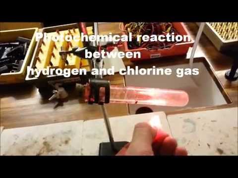
With water injection into the exhaust all chlorine radical can be purified out of the exhaust stream.
Using this process to dissociate water with sodium chloride electrolyte and 10-25% NaOH or KOH mixture would catalyze the sodium ion to be transverse between the chloride and OH group. Rendering the chlorine to bubble off with greater redox flow than normally witnessed. The benefit of this is the photochemical reaction of Hydrogen with Chlorine gas. If the HHO stream is passed through an electron extraction mesh electrode, the resultant gas can be subjected to UV light and cause the spontaneous photoelectrochemical reaction between Chlorine and Hydrogen. Roughly 14 times the combustive force than gasoline of equal volume.
see here:
With water injection into the exhaust all chlorine radical can be purified out of the exhaust stream.
https://www.researchgate.net/publica...1MBbptQ70U9mt0
This is essentially just creating a optical oscillator and putting conductive ions in the path of the oscillating wave. In theory by using high voltage pulsed current would be more effective than constant current or AC.
What do you think?
This is essentially just creating a optical oscillator and putting conductive ions in the path of the oscillating wave. In theory by using high voltage pulsed current would be more effective than constant current or AC.
What do you think?
Alright, all of the materials for the alloy activation chamber have arrived, will be picking them up sometime this week. The chamber itself being built sometime within the next 2-3 weeks. Activation will take 1-2 days. I'll try to remember the phone for capturing the build and activation procedures. The main difficulty now is finding a source of hydrogen gas, until we get that the activation can not happen.

i need 99.9999% pure chemical grade pressurized H2 gas, i'll be using it around 8bar
MHD technology great tech, requires tremendous levels of magnetic fields to generate useful power. 3+ Tesla
My batteries are best for long term power supply but not instantaneous high power demand, due to the nature of the chemical reaction.
I am fascinated with MHD and am confident that i have a design that could work VERY well and use rare-earth permanent 8+ T magnetic rings. It would be heavy, but could generate in excess of 100kw+ for medium units. Only needing HHO or molten salt input
MHD is one of my favorite future technologies for scaling down to commercial- civilian application.
the major issue is that MHD does not scale down very well as it is a mass and velocity dependent energy generation mechanism. At least the conventional application. So it can only be scaled down so much, until it costs WAAAAAy more to operate than it off-sets from energy production
an ingenius technology that will soon be discovered by human scientists is the ability for silicates and some crystalline formations to generate "excess" energies when in a MHD setup, where an applied photon beam generates statically polarized vibration within the crystal lattice and an applied magnetic field will force the charge to flow in certain directions. This is known as solid-state mhd effects. This technology could be used to not only breed anti-matter (different subject) but also generate massive surplus' of electrical energy in the form of mainly high voltage potential gradients. If used as the particle accelerator mechanisms for a Liquid Metal-Room temperature MHD dynamo, then the velocities and low-power requirements for civilian scale MHD tech is possible
The issue then becomes R&D, investment cost, and liquid metal choice..... because mercury and mercuric alloys are the best choice and more power-dense at the given temp requirements.... gallium works, but needs fine tuning
If a thin Palladium or Platinum coated carbon layer is placed over Sterling Engines piston chambers, HHO can be directly used, without need of combustion, to power the sterling, no problem. However the energy to generate super heated steam, run a stirling, create gas, just to harness the ionic differential of the gaseous streams would leave you with more energy loss than energy gain. A more efficient process is just to power a turbine from the Steam, and put the MHD on the output of the steam generator system (whether HHO, or CO2, Coal or Natural gas, or Thermal) Less room for loss.
HHO can be used in a MHD environment, both the H and the O atoms have charge, and conductivity and therefor will function as a reasonable MHD working fluid. The issue lies in the energy required to generate the HHO and accelerate the HHO plasma up to high enough velocities to generate useful current
Also, the major issue with HHO is when the HHO gas is combusted, it reforms back into water. Which can not be used in an MHD unless it contains conductive impurities
i need 99.9999% pure chemical grade pressurized H2 gas, i'll be using it around 8bar
MHD technology
great tech, requires tremendous levels of magnetic fields to generate useful power. 3+ TeslaMy batteries are best for long term power supply but not instantaneous high power demand, due to the nature of the chemical reaction.
I am fascinated with MHD and am confident that i have a design that could work VERY well and use rare-earth permanent 8+ T magnetic rings. It would be heavy, but could generate in excess of 100kw+ for medium units. Only needing HHO or molten salt input
MHD is one of my favorite future technologies for scaling down to commercial- civilian application.
the major issue is that MHD does not scale down very well as it is a mass and velocity dependent energy generation mechanism. At least the conventional application. So it can only be scaled down so much, until it costs WAAAAAy more to operate than it off-sets from energy production
an ingenius technology that will soon be discovered by human scientists is the ability for silicates and some crystalline formations to generate "excess" energies when in a MHD setup, where an applied photon beam generates statically polarized vibration within the crystal lattice and an applied magnetic field will force the charge to flow in certain directions. This is known as solid-state mhd effects. This technology could be used to not only breed anti-matter (different subject) but also generate massive surplus' of electrical energy in the form of mainly high voltage potential gradients. If used as the particle accelerator mechanisms for a Liquid Metal-Room temperature MHD dynamo, then the velocities and low-power requirements for civilian scale MHD tech is possible
The issue then becomes R&D, investment cost, and liquid metal choice..... because mercury and mercuric alloys are the best choice and more power-dense at the given temp requirements.... gallium works, but needs fine tuning
If a thin Palladium or Platinum coated carbon layer is placed over Sterling Engines piston chambers, HHO can be directly used, without need of combustion, to power the sterling, no problem. However the energy to generate super heated steam, run a stirling, create gas, just to harness the ionic differential of the gaseous streams would leave you with more energy loss than energy gain. A more efficient process is just to power a turbine from the Steam, and put the MHD on the output of the steam generator system (whether HHO, or CO2, Coal or Natural gas, or Thermal) Less room for loss.
HHO can be used in a MHD environment, both the H and the O atoms have charge, and conductivity and therefor will function as a reasonable MHD working fluid. The issue lies in the energy required to generate the HHO and accelerate the HHO plasma up to high enough velocities to generate useful current
Also, the major issue with HHO is when the HHO gas is combusted, it reforms back into water. Which can not be used in an MHD unless it contains conductive impurities
Another battery chemistry for those who want to DIY, this is cheaper than zinc but slightly less energy density.
Iron ion Air Battery-Rechargable:
Negative Electrode:
Iron powder, Ink solution of Graphene Oxide coated Magnetite (can be made by lookng up Robert Murray Smith's videos), addition of garlic based carbon and between 0.1-0.9%wt ABtype Metal Hydride material. Make a binder out of garlic oil (from fresh garlic) and 2-5%wtPTFE or other binder and pasted onto a conductive electrode mesh. Addition of FeS and BiS from 2-10% wt can improve cell life time and reduce hydrogen evolution.
Positive electrode (two of these per 1 negative):
conductive porous scaffold material, graphitized carbon with high surface area carbon based ink, addition of NiO, Ag powder, CoO for ORR and OER, coat the scaffold in the ink, freeze dry, then photonically "sinter" by flashing with a high flash xenon bulb. This reduces the oxygen and exfoliates the carbon lattice-increasing surface area.
Electrolyte: Liquid or gel
Gel: 1.Sodium polyacrylate with water and KOH
2. PVA,water,KOH
3. other gel type of choice
liquid: NaOH or KOH and water, possible addition of 0.1-.4%Li(OH) for increase in capacitance
The gel version of these with a GANS paste outer layer for the oxygen side may scavange CO2 and prevent caronization of the air-based electrodes. Either this, or the batteries can be used in tandem with an electrolysis cell is used and the "waste" oxygen is used to keep the O2 concentration higher than the CO2 concentration at the surface of the air electrodes. These batteries are relatively cheap, easy to recycle, easy to manufacture, and reasonably powerfull at 1.28-1.4V and 400-900mAh\g average
Iron ion Air Battery-Rechargable:
Negative Electrode:
Iron powder, Ink solution of Graphene Oxide coated Magnetite (can be made by lookng up Robert Murray Smith's videos), addition of garlic based carbon and between 0.1-0.9%wt ABtype Metal Hydride material. Make a binder out of garlic oil (from fresh garlic) and 2-5%wtPTFE or other binder and pasted onto a conductive electrode mesh. Addition of FeS and BiS from 2-10% wt can improve cell life time and reduce hydrogen evolution.
Positive electrode (two of these per 1 negative):
conductive porous scaffold material, graphitized carbon with high surface area carbon based ink, addition of NiO, Ag powder, CoO for ORR and OER, coat the scaffold in the ink, freeze dry, then photonically "sinter" by flashing with a high flash xenon bulb. This reduces the oxygen and exfoliates the carbon lattice-increasing surface area.
Electrolyte: Liquid or gel
Gel: 1.Sodium polyacrylate with water and KOH
2. PVA,water,KOH
3. other gel type of choice
liquid: NaOH or KOH and water, possible addition of 0.1-.4%Li(OH) for increase in capacitance
The gel version of these with a GANS paste outer layer for the oxygen side may scavange CO2 and prevent caronization of the air-based electrodes. Either this, or the batteries can be used in tandem with an electrolysis cell is used and the "waste" oxygen is used to keep the O2 concentration higher than the CO2 concentration at the surface of the air electrodes. These batteries are relatively cheap, easy to recycle, easy to manufacture, and reasonably powerfull at 1.28-1.4V and 400-900mAh\g average
so, i've been thinking about doping my activated carbons with silver nano-particles. Should i pursue a graphite/carbon and acetlycarboxylicacid-silver complex and pyrolize at 300C or should i make a supernatant Ag-colloidal suspension, put in highly porous activated carbon and freeze-dry the material?
the left over carbon product from either method would be used in battery electrodes/electrochemical cells specifically printed Ni-Fe, Ni-FeMH, and hydrogen generation chemistries . As well as Ni-Al,Carbon-Al, Carbon-Carbon,or Proton batteries
the carbons i use are a ball milled combination of ZnCl microwave assisted activated carbon mixed with 45 micron conductive graphite powder.
Mke colloidal silver, in a super natant solution and pour in your active carbon material then freeze-dry to get silver in carbon
What do you think?
the left over carbon product from either method would be used in battery electrodes/electrochemical cells
specifically printed Ni-Fe, Ni-FeMH, and hydrogen generation chemistries . As well as Ni-Al,Carbon-Al, Carbon-Carbon,or Proton batteries the carbons i use are a ball milled combination of ZnCl microwave assisted activated carbon mixed with 45 micron conductive graphite powder.
Mke colloidal silver, in a super natant solution and pour in your active carbon material then freeze-dry to get silver in carbon
What do you think?
Some pics of the alloy before activation, currently waiting for the pieces to build the activation vessel. This is a AB4.3 alloy of La-Ni-Co-Al the outside is an oxide coating from the annealing process, easily brushed off to reveal the lustrous silvery metal alloy underneath. I have about 150g, all of it going into 1 electrode
the electrode material is going to be PTFE-60% etOH sol with high conductivity silver intercalated graphite powder, and this alloy in powdered and activated form the support will be nickel metal mesh. counter electrode is nickel metal mesh.
coming together quite rapidly, i am excited to see how the proof-of concept performs


the outside is an oxide coating from the annealing process, easily brushed off to reveal the lustrous silvery metal alloy underneath. I have about 150g, all of it going into 1 electrode the electrode material is going to be PTFE-60% etOH sol with high conductivity silver intercalated graphite powder, and this alloy in powdered and activated form
the support will be nickel metal mesh. counter electrode is nickel metal mesh.coming together quite rapidly, i am excited to see how the proof-of concept performs
The chief advantage of the hydro-battery concept is it's ability for user-versatility in how the hydrogen is utilized. It's pure enough for chemistry and lab work, it has enough flow rate to be used in both ICE and FC applications, and can run on any DC or AC input source, ideally from Off-peak PV. Then the energy is safely stored in the device, electrical input is turned off, the tank can simply be plugged in to any required system. Water and electricity are the only "fuels".
Most definitely the possibility of it overheating is greatly reduced!!
I am excited for this, will be posting pictures and videos as the project evolves will be posting the activation procedures soon
The device is limited by weight, sadly, it's heavier than li-ion currently (will change as i advance the tech) but rights now for every 1.6kg of battery device, it will store 300Ah on average it still needs a fuel cell. I am also working on a MUCH MUCH lighter version, it has less storage density but is lighter than Li-ion and has equal storage density (lower average voltage though).
I definitely have something for a drone-blimp as well. With every additional 1kg of weight is a percentage of power that goes to maintaining the weight and not going to the thrust vector. It can supply anywhere from 12-48+V and over 8 amps. The current is dependant on the fuelcell used, like a 300W fuel cell puts out 36V@8amps and the 1.6kg battery can power this for 2 hours roughly. It weighs 1.6kg without the fuel cell, the fuel cell weighs about 2kg. With all the fans and heat-controlling circuits, without the fans it weighs about 1.4kg. The basics is the standard liters of storage, my battery can store 300L of H2 per 1.6kg of alloy, 300L can power a 300W FC for 2 hours at a rate of 3.6L per minute of consumption. The fuelcell can also be altered to fit your application. Also, the entire thing can come in smaller versions as well you can have all the way down to only 1W if you want. It's best to go for a FC battery system. Such as, if your drone requires 400W of power 250W comes from the FC and 150W comes from the battery, but the battery also has enough storage to safely land the drone in the advent of sudden hydrogen loss.
What do you think?
Most definitely the possibility of it overheating is greatly reduced!!
I am excited for this, will be posting pictures and videos as the project evolves
will be posting the activation procedures soonThe device is limited by weight, sadly, it's heavier than li-ion currently (will change as i advance the tech) but rights now for every 1.6kg of battery device, it will store 300Ah on average
it still needs a fuel cell. I am also working on a MUCH MUCH lighter version, it has less storage density but is lighter than Li-ion and has equal storage density (lower average voltage though). I definitely have something for a drone-blimp as well. With every additional 1kg of weight is a percentage of power that goes to maintaining the weight and not going to the thrust vector. It can supply anywhere from 12-48+V and over 8 amps. The current is dependant on the fuelcell used, like a 300W fuel cell puts out 36V@8amps and the 1.6kg battery can power this for 2 hours roughly. It weighs 1.6kg without the fuel cell, the fuel cell weighs about 2kg. With all the fans and heat-controlling circuits, without the fans it weighs about 1.4kg. The basics is the standard liters of storage, my battery can store 300L of H2 per 1.6kg of alloy, 300L can power a 300W FC for 2 hours at a rate of 3.6L per minute of consumption.
The fuelcell can also be altered to fit your application. Also, the entire thing can come in smaller versions as well you can have all the way down to only 1W if you want. It's best to go for a FC battery system. Such as, if your drone requires 400W of power 250W comes from the FC and 150W comes from the battery, but the battery also has enough storage to safely land the drone in the advent of sudden hydrogen loss. What do you think?
ARRRGGHHHH, the wholesale company i am in contact with will only sell a minimum of 20 kg of metal alloy XD i only need 1kg for the tests... I have no other choice, but to buy the alloy. This is n unfortunate set-back. The experimental set-up only has 150 grams in it, which i already have, but i'll need another 1kg for the later device. At least 3kg for making 2 hydrogen storage canisters, but 20kg?? woooo that's 19 bottles of hydrogen storage alloy XD at 400SL per canister, haha that's a lot of storage.
I am thinking i'll just sell the other remaining canisters of alloy i receive, since i'd be getting them at wholesale prices. If anyone is interested in a Hydrogen storage alloy LMK!! They'll be on sale, cheaper the more you buy!
I am thinking i'll just sell the other remaining canisters of alloy i receive, since i'd be getting them at wholesale prices. If anyone is interested in a Hydrogen storage alloy
LMK!! They'll be on sale, cheaper the more you buy!
Yes, the FET controls the frequency the circuit operates at, the thyristor controls the amount of time that frequency is applied to the circuit. They are acting in synchronization.
just wondering peoples opinions, it's a circuit that i am working on for an electric bike
I need a proof of concept for my battery design, so i am looking at ways to make something that is both functional, compact, and innovative. Since the battery is wired in such a way 95% of the time it is being charged by an on-board generator, a small 24V generator (only a few amps) which can be toggled on and off. This is the basic circuit. I am now working on the logical circuits for monitoring circuit conditions and toggling the generator and battery connection (not shown but an arduino will regulate the output of the comparator.
I need a proof of concept for my battery design, so i am looking at ways to make something that is both functional, compact, and innovative. Since the battery is wired in such a way 95% of the time it is being charged by an on-board generator, a small 24V generator (only a few amps) which can be toggled on and off. This is the basic circuit. I am now working on the logical circuits for monitoring circuit conditions and toggling the generator and battery connection (not shown but an arduino will regulate the output of the comparator.
The two switches are because the thyristor is necessary to carry high current loads into the coil primary, while the FET acts as a gate switch for application of a current frequency. By increasing the frequency that the FET is triggered the current applied to the coil increases. While the Thyristor simply carries the high current load and keeps the pulse width within 300nano-seconds
If anyone reading this has a toyota mirai.... when you get bored and want the next big thing.... i am more than happy to take it off your hands  ooooooo to get under the chasis and look at that custom-made marvel of engineering the 114 Kilowatt fuel cell!!! Haha
ooooooo to get under the chasis and look at that custom-made marvel of engineering the 114 Kilowatt fuel cell!!! Haha
asking for feedback
#1 ·
deltaT<(1/4D)-(Xad/x)^2
deltaT=Pulse Width Duration in Nano-seconds (3-300ns)
D=the diffusion coefficient (cm^2 s^-1) 2.3x10^-5cm^2 s^-1
Xad= the density of Hydrogen ions on the cathode (cm^-2) 10^15cm-2 (for Platinum specifically, each electrode material is different, slightly)
X= the concentration of Hydrogen ions in the solution (cm^-3) 6x10^20cm^-3 for 1M of KOH solution.
Formula for pulsed DC electrolysis where by the application of current at Ultra-Short pulse width of 3-300nano-seconds at 25-40+Khz. The increasing of electrical frequency increases the applied current, pulse width must remain static in order to prevent the diffusion layer and electron double layers from forming on the the surface of the electrode. Thus instead Virtual breakdown occurs at the surface of the electrode and within the E-field generated surrounding the anode and cathodes respectively. The high frequency "impulse current" (high voltage of peak current @ 140V 0.3-1 amp per "cell"). If cell electrodes are 3cm apart, the device will produce H3O and OH(-+) radicals which will then decompose into H2 ions and 1/2O2. This is purely a field effect, and therefor the decomposition of the water is due to Virtual forces exerted upon the dipole nature of the H2O atoms.
What do you think?
deltaT=Pulse Width Duration in Nano-seconds (3-300ns)
D=the diffusion coefficient (cm^2 s^-1) 2.3x10^-5cm^2 s^-1
Xad= the density of Hydrogen ions on the cathode (cm^-2) 10^15cm-2 (for Platinum specifically, each electrode material is different, slightly)
X= the concentration of Hydrogen ions in the solution (cm^-3) 6x10^20cm^-3 for 1M of KOH solution.
Formula for pulsed DC electrolysis where by the application of current at Ultra-Short pulse width of 3-300nano-seconds at 25-40+Khz. The increasing of electrical frequency increases the applied current, pulse width must remain static in order to prevent the diffusion layer and electron double layers from forming on the the surface of the electrode. Thus instead Virtual breakdown occurs at the surface of the electrode and within the E-field generated surrounding the anode and cathodes respectively. The high frequency "impulse current" (high voltage of peak current @ 140V 0.3-1 amp per "cell"). If cell electrodes are 3cm apart, the device will produce H3O and OH(-+) radicals which will then decompose into H2 ions and 1/2O2. This is purely a field effect, and therefor the decomposition of the water is due to Virtual forces exerted upon the dipole nature of the H2O atoms.
What do you think?
Circuit for High Frequency Ultra-short Pulse Width DC Voltrlysis. Where the decomposition of the water molecule is the result of HF Virtual break down in a resonant-step-charged capacitor. The resulting gas can be used as seen fit. The overall circuit will maintain it's efficiency even as applied current is increased. This cell system is designed to operate high efficiency, low power consumption and consolidate storage, purification, and pressurization requirements within one device. (This only only for the version of this device where special metal alloys are used at the negative electrode. Standard HHO gas can be created otherwise).
Normal water would work in this setup, any water would work. Normal, sea, urine, rain, waste water, etc etc. This circuit prevents the Electron Double Layer and Electron Diffusion Layers from forming, which prevents brute-forcing and instead allows for Virtual breakdown
For circuit estimations, the total current moving through the circuit will be maximum 350W generally 12V @1-6amps depending on how many "cells" are connected to the power supply.
For device design, i'd go more for germanium diodes, a Static Induction Thyristor, and a standard FET fit for the current you plan on running through the circuit. For coil winding numbers i gave give you theoretical values for each coil that would suit as good starting points.
Primary can have between 1-560 turns
C2: (@P=560) 2,880 turns
C1:3,000 turns
S:3,020 turns.
The voltage and circuit resonance can be changed based on the turn relationships, and the applied frequency. the Pulse Width is 300ns but the pulse frequency is between 2-25Khz up to 40+Khz. The circuit is experimental, so the values are completely open to be seen. I know what the theory says is an appropriate starting point, but who knows how the circuit will behave once built.
What do you think?