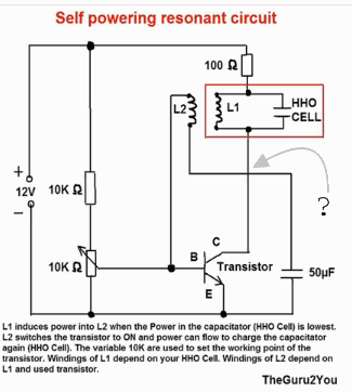
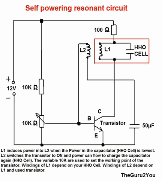
Schematic
Can someone post a schematic of this circuit that Ali is posting?
Thanks
Can someone post a schematic of this circuit that Ali is posting?
Thanks
14 posts · 2 threads started · 91 more in threads this archive does not carry · writing between Feb 2010 and May 2012
An identity on Energetic Forum as it was harvested, not an account on this site. Nobody here has claimed it, and nothing connects it to a person by name.
#2 ·
hydrotom wrote:
hhoheaterplans.com has just open sourced there plans. They are looking to start getting the word out. I know these guys and they are the real deal. I have seen this system running and it is amazing. They felt charging for these plans was holding back the technology from everyone. So they have made it open source..
They have told me that they will also advertise for all energy forums for free..
Thought I would let ya know.
geotron wrote:
With the two intersecting paths here without a mend point does this
represent a connection? If not would the 50uF capacitor benefit from
the use of a blocking diode at transistor to prevent causing flow
backwards through L2 and the 10k potentiometer?
boguslaw wrote:
Guruji
Thanks for link.What transistor did you use ? Is that 50uF cap electrolytic one ?I hardly can find any other with so much uF except big one for motors.
Did yoy replaced HHO cell with speaker of placed a capacitor instead of HHO cell and then speaker parallel to this cap ?
geotron wrote:
When the energy level of the HHO cell, or water-fluid gap is at its
lowest, would you explain the way in which the L2 coil is pulsed
with energy from L1?
Upon entry of positive charge from the battery into the region you've outlined
consisting of the L1 coil and HHO cap, it seems a portion of it also goes through
L2 into filling the 50uf capacitor, but for what purpose?
The amount of energy required to switch a 2n3055 transistor looks to be 1.5V.
12v into 1.5 would require the potentiometer to be set for 1.25 Kohm.
The 50uF capacitor will only charge at a very slow rate with this amount of
current.
120mA into the hho cel and L1 coil from the 100ohm resistor, interesting.
It looks like coil L2 will be pulsed with current from L1 when the 50uF cap's
anode is charged up to an appropriate level.
Michael John Nunnerley wrote:
For many years I thought that this is so close, but for the wrong reasons.
What do you have here, two oscillators at two different frequencies, but they inter react wrongly and you have to get the frequencies right. Think a little differently, make the oscillations independant to start with and only mix them at the point of reaction.
An oscillation at frequency of whatever is a radio frequency depending on the delivery, the bifilar coli is a balun, but it is all set up wrong for it to work as it should, now where would we put the GROUND plane!!!!!!!!!!!!!!!!!!!!!!!!!!hmmmm, lokk at the none electrolysis of water thread and you will see what is needed.
Mike
Sputins wrote:
Vickers,
I asked for you.. I asked the resident chemistry guru, the supervisor of the "general chemistry" department at my workplace. He says its going to be very difficult. He knew of nothing off hand. As the ethanol is soluble in water the dye soluble in ethanol would also be soluble in the water..
Tough one, not saying that there isn't somthing, but chances are you wont find anything..
I gather you are vacuum distilling the ethanol. This is a very worthy effort. I would be interested in a small set-up myself for fuel purposes.. I have a vacuum pump too.. I gather you are familiar with David Bloom's work?
Good luck with it..!
Stealth wrote:
The easiest thing to do, if you can't buy or find a battery, is to build a Leyden jar. They are simple to build, and you can build any size needed. They should be able to handle any amount of current and will store it just as a battery or capacitor. They are now in the process of building some very large capacitors that will make batteries obsolete. Good Luck.. Stealth
linesrg wrote:
Guruji,
This is a devleopment of the well known Dave Lawton twin 555 timer based PWM.
This device generates a varying signal seeking a resonant point and then locks on to it. It is based on a HEF4046 Phase Lock Loop IC.
Regards
Richard