patent · US964031
Liquid-hydrocarbon-burning apparatus.
12 July 1910
Page 1
Drawing sheet — no readable text.
Page 2
Drawing sheet — no readable text.
Page 3
UNITED STATES PATENT OFFICE.
LoUIS K. LEAHY, o F Los ANGELES, CALIFORNIA.
LIQUID-HYDROCARBON-BURNING APPARATUS.
9??,081. . Specification of Letters Patent. Patented July 12, 1910.
To all whom it may concern: cooled by contact with the boiler flues or Be it known that I, LOUIs K. LEAHY, a other surface to be heated, to the ignition citizen of the United States, residing at Los chamber or the main consuming or burning Angeles, in the county of Los Angeles and chamber, or both, and intermingling the 5 State of California, have invented certain same with the injected fuel and thus again 60 Improvements in Liquid-Hydrocarbon subjecting such partially consumed product Burning Apparatus, of which the following to intense heat thereby insuring the total is a specification. m consumption thereof.
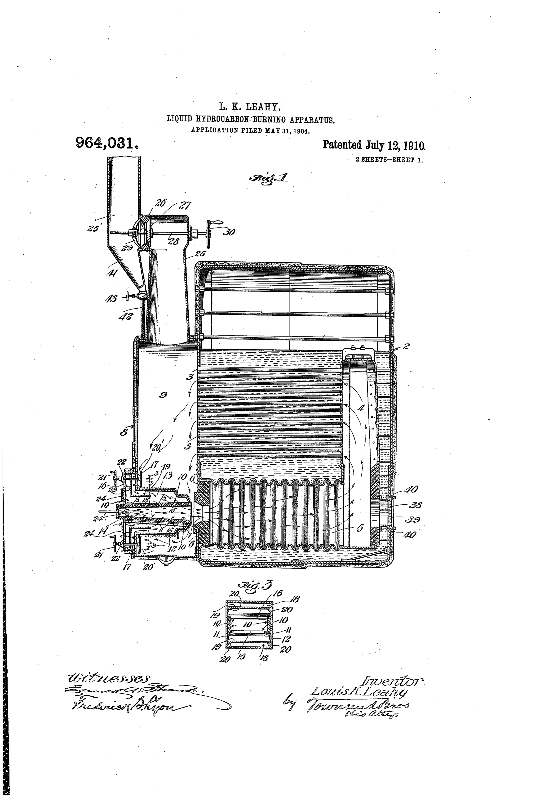
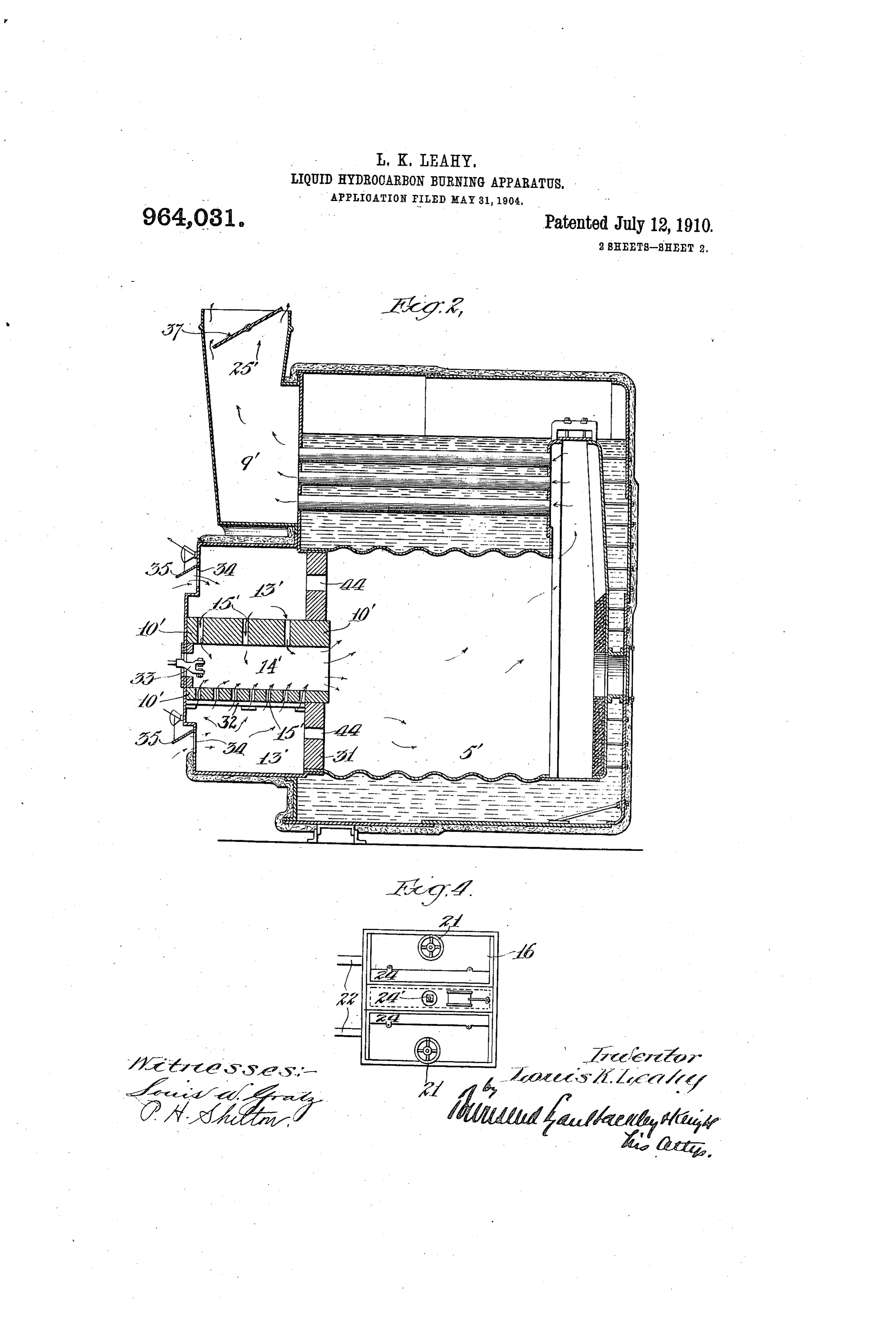
This invention relates to apparatus for The invention consists further in the con O burning liquid hydrocarbons for fuel pur structions and in combination of parts all 65 poses and more especially for heating pur as hereinafter described and particularly set poses, either under steam boilers or other out in the claims, and will be more readily apparatus in connection with which it is understood by reference to the accompany desired to generate an intense heat. ing drawings, forming part of this specifica 5 The primary object of the invention is to tion, and in which :- 70 eliminate the production of Smoke in burn Figure 1 is a longitudinal sectional view ing of such fuel and to entirely consume the of a liquid hydrocarbon burning apparatus fuel and all gases generated by such com embodying my invention. Fig. 2 is a par bustion and to do away with all the incon tial longitudinal section of a slightly modi 20 veniences and annoyances resulting from fied form thereof. Fig. 3 is a transverse 75 smoke and soot from chimneys. sectional view on the line a-ac of Fig.1. A further object of the invention is to Fig. 4 is a detail front view of the removable secure perfect and complete combustion of ignition chamber.
the fuel and the application of all heat In Fig. 1 I have shown my invention as 25 thereby generated to heating the desired applied to a marine boiler of the common 80 chamber or material. type. 2 represents the boiler shell which A further object is to provide such appa may be of ordinary. or any preferred con ratus in simple cheap, durable and efficient struction, and 3 the boiler flues which, as form, which shall not be likely to get out shown, lead through the water chamber. At 30 of order or to require expensive repairs or the rear end of the boiler flues I form a ver- 85 close attention and which shall be exceed tical chamber 4, which leads upward past ingly economical. the boiler flues from the main consuming To these, and such other objects and ends or burning chamber 5, which chamber 5 may as hereinafter appear from the detail de be of the ordinary or any preferred con 35 scription of construction and operation, the struction, its front wall being preferably 90 invention consists primarily in an ignition made up of fire-brick 6 having a central in chamber into which the liquid fuelis in let 7, the mouth of which is inwardly con jected under pressure, a main burning or verging. 8 represents an outer fire-wall or consumption chamber into which the burn shell for the front end of the boiler forming 40 ing fuel is projected from the ignition between the water chamber and main con- 0Es
leading and asaidcontinuous burningduct or or passage suming consuming chamber thereof and such front wall, a vertical chamber 9 which extends from chamber under, about, or through the cham below the inlet 7 up above the top flues 3 of ber or body to be heated, and back to and the boiler. This wall 8 is provided with an 45 communicating with the main consuming opening at its base into which the removable 10. or burning chamber, or which leads into the fire-box, forming the ignition chamber, is ignition chamber, or both. adapted to be inserted into place, as shown. The invention consists further in the pro This fire-box consists of fire-brick 10 ar vision of means whereby air under atmos ranged to provide a tapering chamber, the 50 pheric pressure is supplied to the atomized walls of which diverge toward the outlet i?: fuel, in the ignition chamber, to supply end of the chamber so that when the remov the desired proportions of carbon, oxygen, able fire-box is placed in position the large hydrogen and nitrogen. or outlet with
disposed
The invention further consists in means preferably respect to the inlet 7, but is 55 for returning the partially consumed gases, spaced apart from the walls of 10
Page 4
the inlet 7 a sufficient distance to allow an outer end of the rod 28 is passed through the 65 indraft of gases from the chamber 9 into wall of the chimney and through a bearin the inlet 7 as hereinafter referred to. The provided therefor and an operating whee fire-brick 10 is supported by angle plates 11 30 provided on its outer end. The spider 29 and ring 26 for the damper seat are pref 70 suitably mounted upon the main frame 12 erably formed integral, though any other of the removable fire-box or pot, as shown preferred construction may be employed. best in Fig. 3. In Fig. 2, I have illustrated a modified Toward the outlet end of the removable fire-box the walls 12 are brought together form of my apparatus. In this modification O so as to form an opening of such size that I have dispensed with the connection of the 75 the edges of such walls rest upon the outer chamber 9 (corresponding to the chamber of Fig. 1) with the chamber 13' (corre surfaces of the fire-brick 10, as shown. The 9sponding chamber 13 is thus formed about the ignition it will be tonoted the chamber 13 of Fig. 1), and that with this construction chamber 14 formed within the fire-brick.
5 A series of inlets 15 are provided through the gases will not be returned through the 80 the fire-brick from the chamber 13 into the burning or the fuel in either the ignition chamber main consuming chamber. I provide chamber 14, as shown. The front plate 16 is provided with a central aperture through an ignition chamber 14 formed, preferably, which the fire brick 10 extends. This front by brick-work 10' having air-inlets 15 from 20 plate may be supported in position in any the surrounding chamber 13. This brick 85 suitable lets 17 aremanner. From provided, the chamber
the extended 10 is supported on a brick-wall 31 supported on the floor of the main-combus walls 12, into the chamber 13. The inlets. tion chamber as shown, the wall 31 being preferably communicate with the main por continued up to the top wall of such com 25 tion of the chamber 13 through passages 18 bustion chamber as shown. The brick-work 90 formed by a partition19, as shown; the par 10' is also supported on angle-irons 32 from tition 19 being suitably supported on the the walls of the chamber 13. 38 represents inner faces of the walls 12 by angle-plates the atomizing liquid fuel burner or injector. 20 (see Fig. 3). 34 represents air-inlets into the chamber 13, 30 In order to regulate as desired, the inflow the entrance of air therethrough being con 95 through the inlets 17, valves or dampers 20 trolled by means of dampers 35. Air-inlets are provided. These dampers are provided 44 are provided in the wall 31, communicat with suitable stems leading out through ing from the chamber 13 to the main con bearings on the front plate and provided suming or fire chamber 5. In the chimne 35 with hand wheels 21 ¥??ereby they may be flue 25 a damper 37 is provided by whic operated to partially or wholly close the in the outlet through the chimney flue may be 00 lets 17. regulated. This damper may be operated 22 represents pipes leading into the cham from without the flue by any of the well ber 13, preferably behind the partition. 19. known means.
40 These pipes preferably lead from the outer The operation is as follows: When it is 05 air outside the boiler room but may be con desired to “fire up' the damper is turned to nected with any suitable air supply. allow free draft out through the chimney. The front plate 16 is provided with air The supply of atomized liquid fuel is turned inlets 23, dampers 24 being provided in con on and flows out through the atomizer into 45 nection therewith whereby the ingress of the ignition chamber where it is ignited in air ???! the inlets 23 may be regulated the usual or any preferred manner. In 10 as desired. burning heavy crude asphaltum oil (as for 24 represents an atomizing burner for instance the California oil) ignition may not Supplying atomized liquid hydrocarbon fuel be instantaneous and an accumulation, of 50 to the ignition chamber 14. This atomizer highly inflammable gas, may take place in is connected by suitable pipes with a suitable the main consuming chamber. The ignition 15 source of supply for furnishing, liquid hy of this may produce more or less of an ex drocarbon and expansive fluid (either steam plosion. To compensate for this and to re or compressed air) to the atomizer under lieve the boiler and walls of the chamber 55 pressure. from the shock resulting from any such ex 20 At the top of the chamber 9 I provide a plosion, I provide an outlet 38 in the rear wall opposite the main consuming or fire chimney 25, which may be of any ordinary chamber and provide a damper 39 therefor. or preferred construction. This chimney is The damper 39 is normally held closed by provided with a suitable damper by means springs 40 but upon any such explosion 60 of which the passage of gases out through the chimney may be cut off. This preferably yields outwardly to allow the force of the 25 consists in a seat 26 and a damper 27, the explosion to expend itself through the outlet 38. When the pressure is relieved the heavy damper 27 being mounted on a revoluble rod springs 40 will immediately close the dam 28 having its bearings in a spider 29. The
Page 5
Drawing sheet — no readable text.
Page 6
openings therein, with the combustion cham- two subscribing witnesses, at Los Angeles, ber, the ignition chamber having inlet open- county of Los Angeles, and State of Cali ings leading from the air supply chamber, fornia, this 23rd day of May, 1904. and means for injecting atomized liquid LOUIS K. LEAHY. 5 hydrocarbon into said ignition chamber. Witnesses:
In testimony whereof I have signed my FREDERICK S. LYoN, name to this specification, in the presence of JULIA TowNSEND.

Provenance
- Collection
- Cited prior art
- Original PDF
- patentimages.storage.googleapis.com →
- Filed
- 1904-05-31
- Pages
- 6
- Method
- pdftotext (the PDF's own text layer) + pdftoppm 300dpi page scans
- Source
- Google Patents bibliographic record
- Granted
- 1910-07-12
- Inventors
- Louis K Leahy
- Transcribed from
- patentimages.storage.googleapis.com →