patent · US6067973
Method and system for late cycle oxygen injection in an internal combustion engine
30 May 2000
Page 1 — bibliographic record
United States Patent (19) 11 Patent Number: 6,067,973 Chanda et al. (45) Date of Patent: May 30, 2000
54 METHOD AND SYSTEM FOR LATE CYCLE 5,640,845 6/1997 Ng et al. ................................... 60/274 OXYGEN INJECTION IN AN INTERNAL 5,649,517 7/1997 Poola et al. . 123/585 COMBUSTION ENGINE 5.992,400 11/1999 Meiwes ................................... 123/586
75 Inventors: Ashok A. Chanda, Peoria; Randall R. Primary Examiner John Kwon
Richards, Chillicothe; John T. Vachon, Attorney, Agent, or Firm-Robert J. Hampsch
Peoria, all of Ill. 57 ABSTRACT 73 Assignee: Caterpillar, Inc., Peoria, Ill. A method and System for late cycle injection of oxygen enriched air into the combustion chamber of an internal 21 Appl. No.: 09/235,721 combustion engine is disclosed. The late cycle oxygen 22 Filed: Jan. 22, 1999 injection System is part of an airflow management System that effectively controls the use of oxygen and nitrogen
Related U.S. Application Data available in the intake air. The preferred System comprises 60 Provisional application No. 60/100,021, Sep. 11, 1998. an intake air Separation device adapted for Separating a 7 prescribed portion of intake air into a flow of oxygen 51) Int. Cl.' ...................................................... FO2B 23/00 enriched air and a flow of nitrogen enriched air. The System 52 U.S. Cl. .................. ... 1231585; 123/586 includes an oxygen enriched air flow circuit extending from 58 Field of Search ..................................... 123/585,586, the intake air Separating device to one or more combustion 123/587 chambers and a control device adapted for controlling the introduction of the oxygen enriched air into the combustion 56) References Cited chambers late in a combustion cycle in response to Selected engine operating conditions Such as engine Speed or engine
5,080,061 1/1992 Nishimura ............................... 123/585 enriched air into the combustion chamber occurs late in a 5,147,417 9/1992 Nemser ....................................... 55/16 combustion cycle at a crank angle between about 20 degrees 5,400,746 3/1995 Susa et al. 123/25 C and 120 degrees after top dead center and lasts for a 5,517,978 5/1996 Yi ... . . . ... 123/585 prescribed time interval between about 5 degrees and 20 5,522,349 6/1996 Yoshihara et al. 123/25 C degrees of crank angle movement.
5,526,641 6/1996 Sekar et al. ............................... 60/274 5,553,591 9/1996 Yi ................. ... 123/585 5,636,619 6/1997 Poola et al. ............................. 123/585 18 Claims, 5 Drawing Sheets
Page 2
Drawing sheet — no readable text.
Page 3
Drawing sheet — no readable text.
Page 4
Drawing sheet — no readable text.
Page 5
Drawing sheet — no readable text.
Page 6
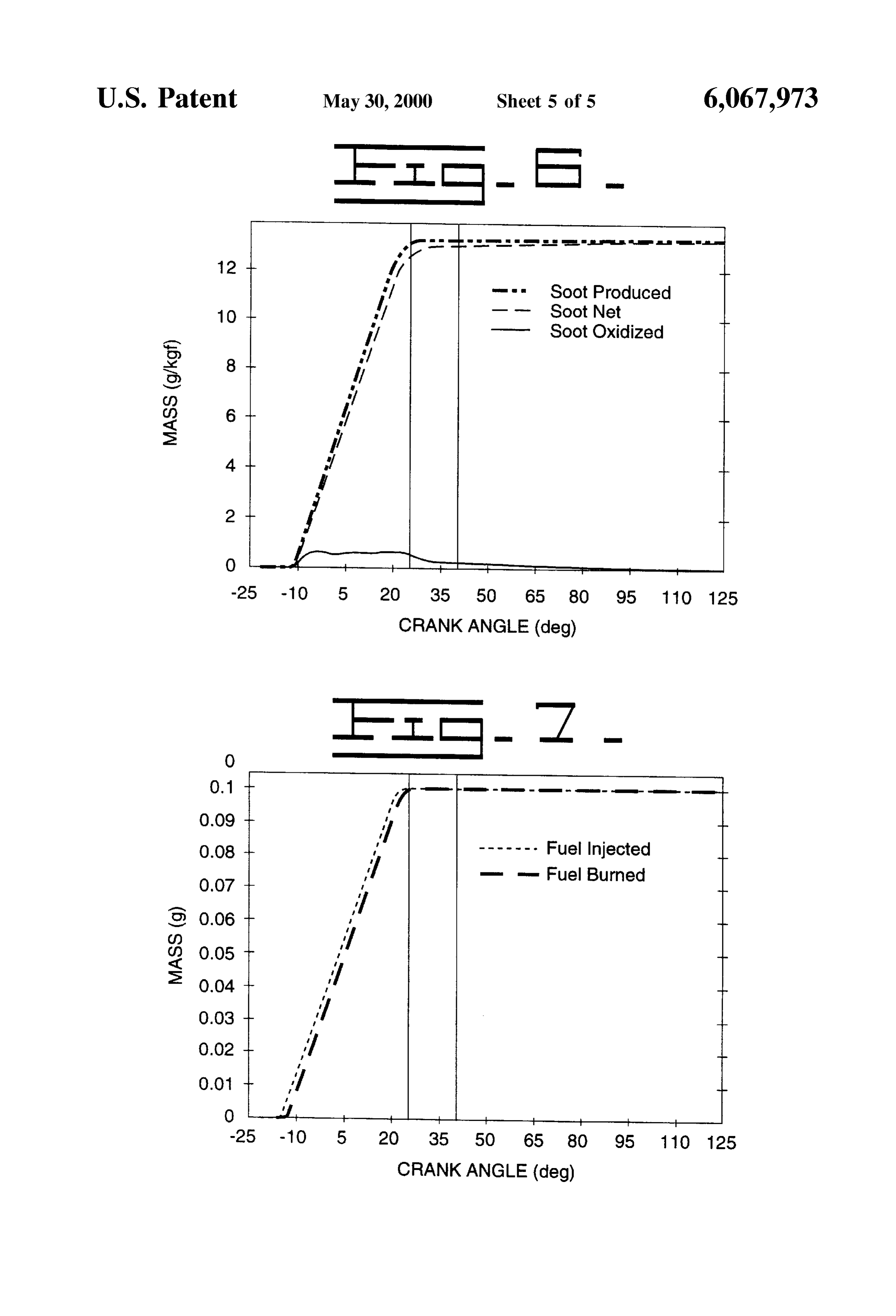
Soot Produced - - Soot Net - Soot Oxidized -25 - 10 5 20 35 50 65 80 95 110 125 CRANK ANGLE (deg)
- un a Fuel Injected H. m. Fuel Burned -25 - 10 5 20 35 50 65 80 95 110 125 CRANK ANGLE (deg)
Page 7
METHOD AND SYSTEM FOR LATE CYCLE bustion cycle as the preSSure and temperature decreases. In OXYGEN INJECTION IN AN INTERNAL addition to decreasing BSFC, increasing air intake oxygen COMBUSTION ENGINE content Serves to reduce the quantity of unburned hydrocar bons by increasing the likelihood of complete combustion.
CROSS REFERENCE TO RELATED Aftertreatment of exhaust gas is useful in reducing the APPLICATIONS amount of unburned hydrocarbons. Aftertreatment methods This application claims the benefit of prior provisional take StepsOne to continue the oxidation of the unburned hydro patent application Ser. No. 60/100,021 filed Sep. 11, 1998. carbons. manner is by introducing a Secondary air Supply into the exhaust Stream. This Secondary air Stream
TECHNICAL FIELD provides more oxygen to the already high temperature exhaust ensuring further oxidation. While using Secondary
The present invention relates to a method and System for air is effective in eliminating particulates, a Secondary air late cycle oxygen injection in an internal combustion engine System creates a higher temperature in the exhaust System. and more particularly to an engine airflow management Designing the exhaust System for these higher temperatures System that involves the dedicated uses of oxygen enriched 15 requires components able to withstand the hotter environ air for reducing engine pollution and increasing engine ment. These components often times are heavier, more performance. More specifically, the present airflow manage expensive, or require more frequent Servicing. ment System involves the introduction of oxygen enriched While particulate production generally decreases along air into the combustion chamber during the later Stages of with fuel consumption, NOX production generally increases. the combustion cycle. NOX forms where nitrogen mixes in a high temperature BACKGROUND OF THE INVENTION Setting with exceSS oxygen not used in the combustion process. Thus, while excess oxygen and high combustion
In recent years, internal combustion engine makers have temperatures are beneficial in reducing fuel consumption, been faced with ever increasing regulatory requirements. 25 Such combination is detrimental in terms of increased NOX These requirements have been directed mainly at two formation. This conflict generally leads engine manufactur aspects of engine performance, namely fuel economy and ers to delicately balance NOx production with BSFC and exhaust emissions. Exhaust emissions takes on a number of particulate matter in order to meet emission regulations. The forms including particulate matter and oxides of nitrogen present invention resolves, at least in part, the continuing (NOx). AS is generally know in the art, particulate matter is conflict between reducing particulates, reducing NOx, and comprised of mainly unburned hydrocarbons and Soot decreasing BSFC.
whereas NOX is an uncertain mixture of oxides of nitrogen Exhaust Gas Recirculation (EGR) is one manner of air (mainly NO and some NO2). Different forms of airflow flow management currently in use to reduce NOX formation management Systems have been used to improve each of within the combustion cylinder. EGR reduces the amount of 35 available oxygen for formation of NOX. By reducing the these characteristics.
One well-known method of decreasing fuel consumption amount of oxygen, the combustion process is also slowed is by increasing the amount of air in the cylinder. Typically thereby reducing the peak temperatures in the combustion this has been accomplished by preSSurizing the air taken into chamber. EGR Systems typically use exhaust gas, however the combustion chamber. The main goal of this pressuriza Poola shows using an enriched nitrogen Source instead of tion is to increase the oxygen available for combustion. 40 exhaust gas to displace oxygen in the combustion chamber. Others have increased the concentration of oxygen in the The enriched nitrogen is both cleaner and cooler than combustion air using air Separation techniques. See, for exhaust gas.
example, U.S Pat. No. 5,649,517 (Poola et al.) issued on Jul. Like particulate matter reduction, NOx emissions may be 22, 1997 which discloses the use of a semi-permeable gas decreased using various after treatment methods. For membrane to remove a portion of nitrogen from the intake 45 example, the Poola et al., Sekar et al., and Ng et al. air flow to create an oxygen enriched air Supply. See also disclosures all show an aftertreatment System using enriched U.S. Pat. Nos. 5,526,641 (Sekar et al.) and 5,640,845 (Nget nitrogen Supply to reduce NOX. AS disclosed therein, the al.) which disclose similar air separation techniques for enriched nitrogen Supply is exposed to a Spark Source to creating oxygen enriched air as well as nitrogen enriched air. form nitrogen plasma. Directing the nitrogen plasma Stream Another related art disclosure of interest is U.S. Pat. No. 50 into the exhaust Stream results in a chemical reaction form 5,553,591 (Yi) issued to on Sep. 10, 1996 which shows a ing nitrogen gas and OXygen gas. Vortex air Separation System for creating oxygen enriched From the above discussion it appears well known that intake air to increase the power generated during combus oxygen enriched air and nitrogen enriched air have a number tion. Introduction of oxygen enriched intake air during the of beneficial uses within an internal combustion engine and intake Stroke facilitates burning a larger part of the available 55 a diesel engine in particular. However, these uses are not fuel injected which in turn increases the power output for always complimentary. Also, production of oxygen enriched each combustion cycle or charge and generally reduces air and nitrogen enriched air requires energy. These energy brake specific fuel consumption (BSFC). Lower BSFC requirements place a limit on the availability of enriched air. correlates Strongly with reduction in unburned fuel. Like any limited resource, the enriched air must be effi Manipulation or control of the airflow system within an 60 ciently managed. In this case, the air flow management engine has also been tried for the purpose of reducing System needs to prioritize power requirements, particulate emissions Such as particulates and NOX. Most particulates formation, and NOX production in light of emission regu generated during the combustion cycle form relatively early lations and operator demand. In most situations, one factor in the combustion cycle, but Such early forming particulates (e.g. power, particulates, or NOx) may dominate over the usually burn as temperature and preSSure increase during the 65 other factors. What is needed therefor is an air flow man combustion cycle. The particulates that typically enter the agement System that effectively balances the emissions and exhaust Stream tend to form in the latter part of the com fuel consumption requirements of an internal combustion
Page 8
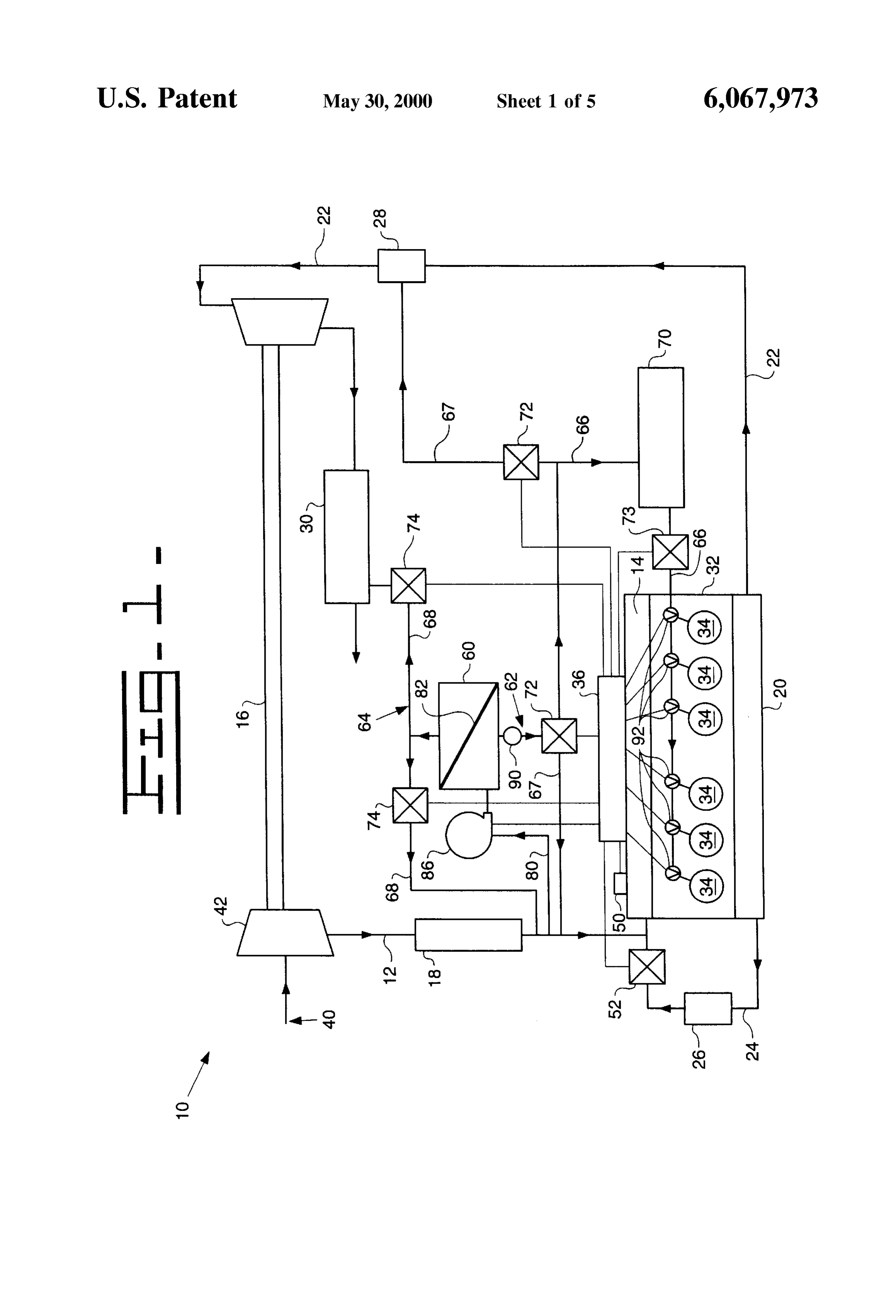
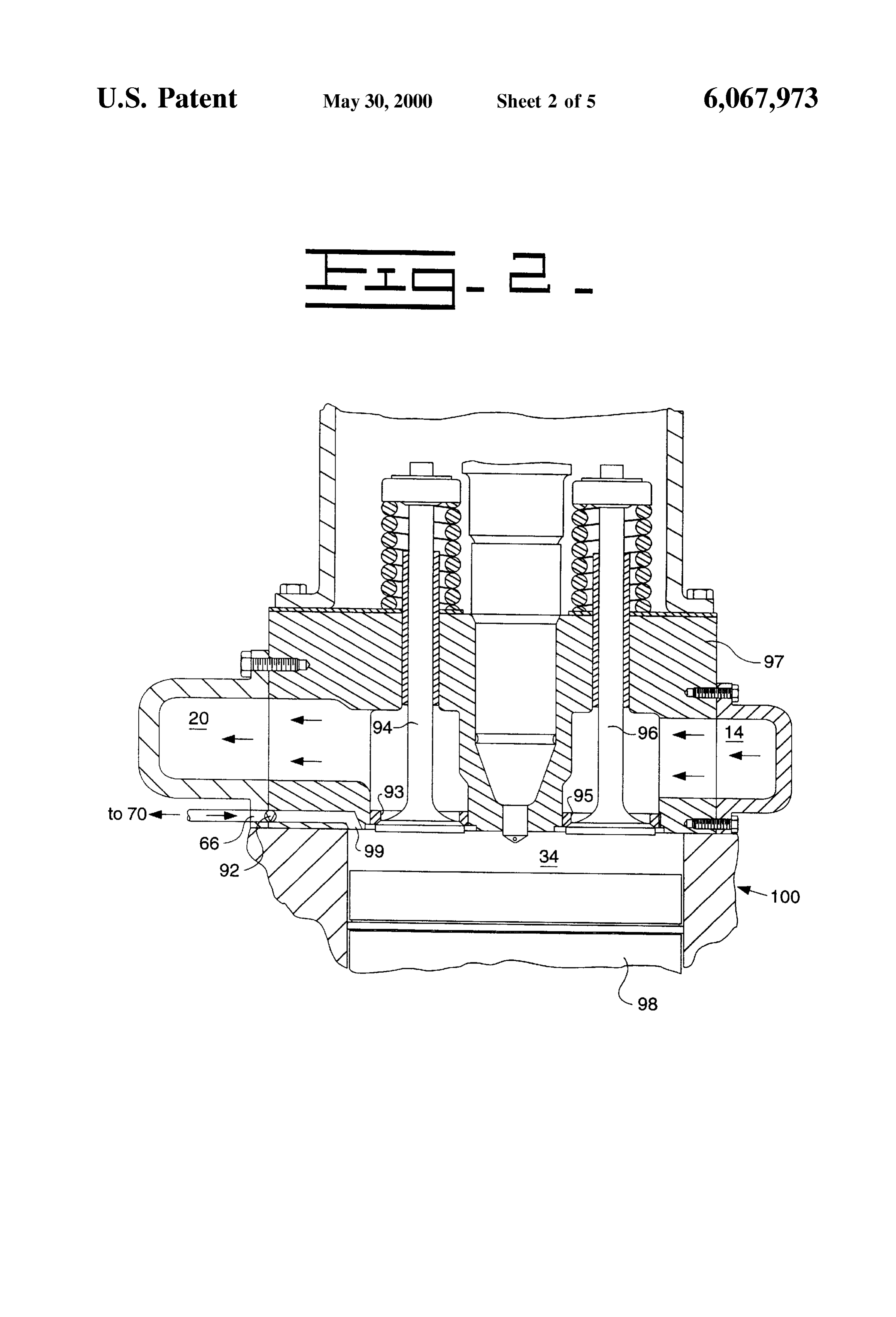
engine, Such as a diesel engine. For instance, under certain FIG. 2 depicts a more detailed view of a combustion operating conditions NOx emissions may be reduced using chamber and air flow management System of the engine of nitrogen in lieu of exhaust gas in an EGR System or by using FIG. 1 and the introduction of oxygen enriched air into the nitrogen within the aftertreatment method, or both. On other combustion chamber late in the combustion cycle; occasions enriched oxygen might be required to either FIG. 3 illustrates a typical cylinder pressure verses piston increase power or reduce particulates. The present invention location graph for the engine of FIG.1 and further graphi is directed at Overcoming one or more of the problems Set cally depicting the introduction of oxygen enriched air late forth above. in the combustion cycle;
SUMMARY OF THE INVENTION
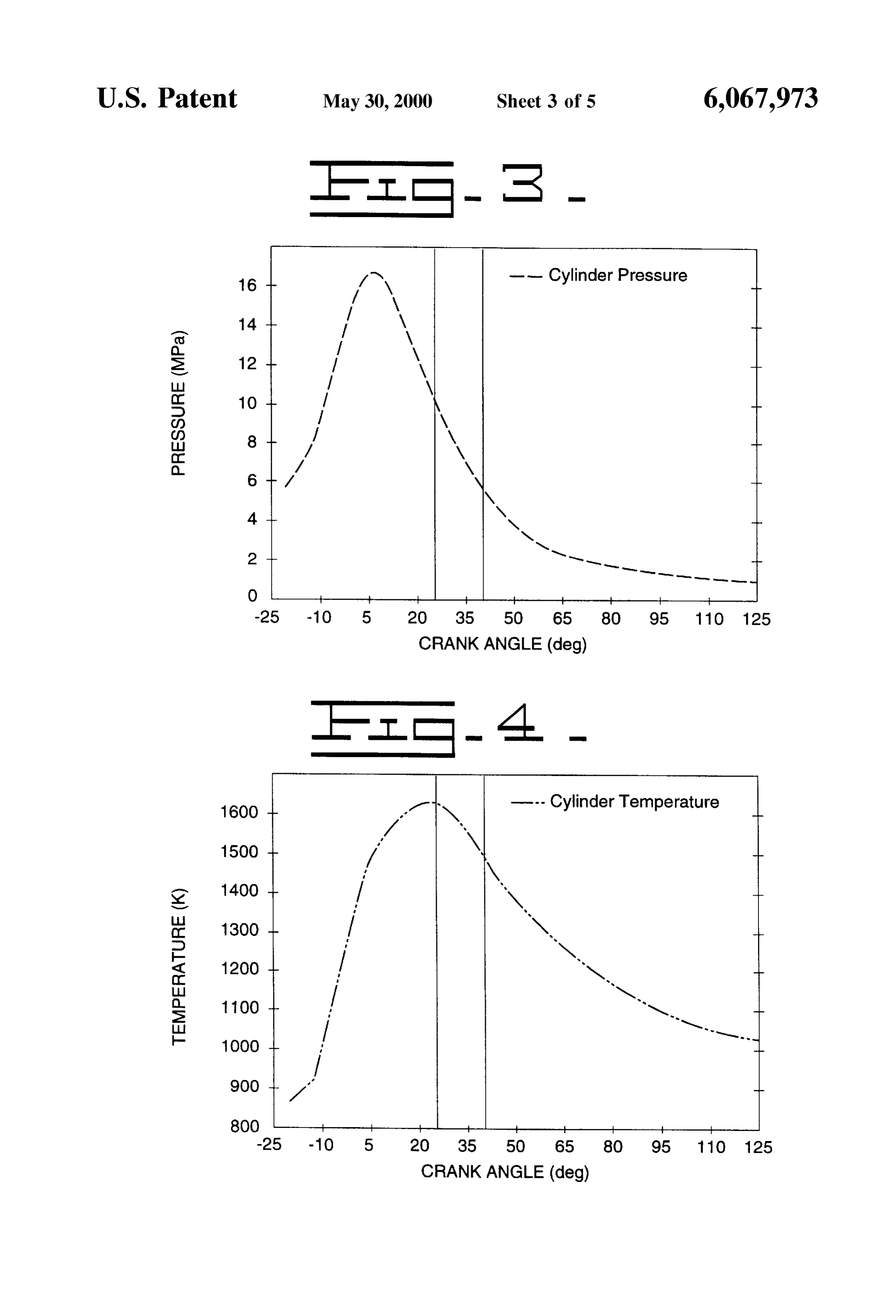
FIG. 4 illustrates a typical cylinder temperature verses piston
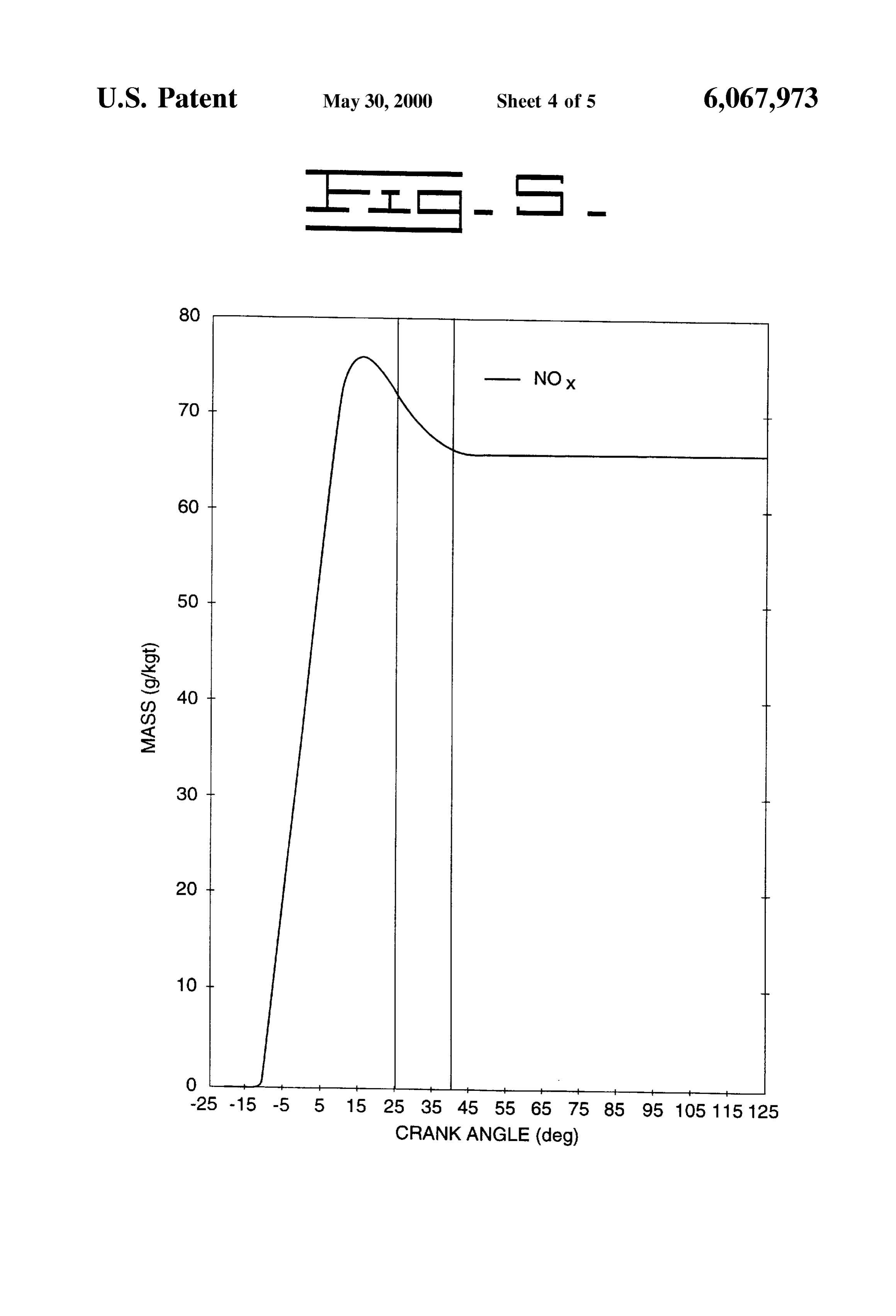
The present invention is a method and System for late graphically location graph for the engine of FIG.1 and further depicting the introduction of oxygen enriched air cycle injection of oxygen enriched air into the combustion late in the combustion chamber of an internal combustion engine. AS disclosed cycle; herein, the late cycle oxygen injection System is an airflow FIG. 5 is a graphical simulation of the NOx content within management System that comprises an intake air Separation 15 a cylinder verses piston location and further depicting the device adapted for Separating a prescribed portion of intake effects of introducing oxygen enriched air late in the com air into a flow of oxygen enriched air and a flow of nitrogen bustion cycle;
enriched air. The System includes an oxygen enriched air FIG. 6 is a graphical simulation of the soot content within flow circuit extending from the intake air Separating device a cylinder verses piston location and further depicting the to a combustion chamber and a control device adapted for effects of introducing oxygen enriched air late in the com controlling the introduction of the oxygen enriched air into bustion cycle; and the combustion chamber late in a combustion cycle in FIG. 7 is a graphical simulation of the fuel injected and response to Selected engine operating conditions Such as burned within a cylinder verses piston location and further engine Speed or engine load or both. depicting the effects of introducing oxygen enriched air late Preferably, the introduction of the oxygen enriched air 25 in the combustion cycle.
into the combustion chamber occurs late in a combustion Corresponding reference numbers indicate corresponding cycle at a crank angle between about 20 degrees and 120 components throughout the Several views of the drawings. degrees after top dead center and lasts for a prescribed time interval between about 5 degrees and 20 degrees of crank PREFERRED EMBODIMENT TO THE angle movement. INVENTION In the disclosed embodiment, the intake air Separation The following description is of the best mode presently device comprises a Selectively permeable membrane device contemplated for carrying out the invention. This descrip adapted for Separating nitrogen from intake air and produc ing nitrogen enriched air at a first outlet and oxygen enriched for the purpose taken tion is not to be
in a limiting Sense but is made merely describing the general principals of the air at a Second outlet. The intake air Separation device also 35 includes an intake air driver adapted for forcibly passing the determined with reference to the of invention. The scope and breadth the invention should be claims.
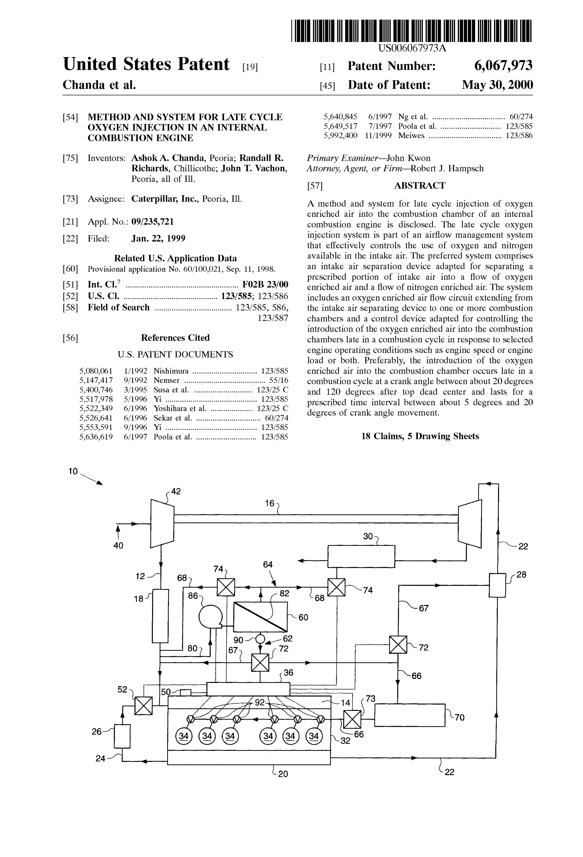
portion of intake air through said Selectively permeable membrane device. Turning now to the drawings and particularly FIG. 1, The invention may also be characterized as a method of there is shown a Schematic diagram of an airflow manage reducing particulate emissions from a compression ignition 40 ment System 10 for an internal combustion engine having an engine comprising the steps of: (a) operating the normal air intake System including an intake air conduit 12, an intake and compression Strokes of the compression ignition intake manifold 14, exhaust gas driven turbocharger 16, an engine including inducting a charge of intake air from the air to air aftercooler (ATAAC) 18; an exhaust system includ intake manifold into the combustion chamber, compressing ing an exhaust manifold 20, a primary exhaust gas conduit the charge of intake air in the combustion chamber, intro 45 22, and optionally an exhaust gas recirculation (EGR) con ducing fuel into the combustion chamber and igniting the duit 24, EGR cooler 26, particulate trap 28, and aftertreat mixture of fuel and charge of compressed intake air to form ment Subsystem 30; and a main combustion section 32 that expanding exhaust gas within the combustion chamber; (b) includes, among other elements, a plurality of combustion introducing a charge of Supplemental oxygen enriched air cylinders each having a fuel injector (not shown) associated into Said combustion chamber late in a combustion cycle 50 there with, an intake port, an intake valve, an exhaust port, an after ignition of the mixture of fuel and charge of com exhaust valve, and a reciprocating piston moveable within pressed intake air, wherein the charge of Supplemental the cylinder to define the combustion chamber 34. The oxygen enriched air reacts with the exhaust gases resident engine also includes an engine control module (ECM)36 for within in Said combustion chamber to form exhaust gases operatively controlling the fuel injection and air System having reduced particulate content; and (c) moving said 55 Valve operations in response to one or more measured piston assembly within Said cylinder to expel Said exhaust engine operating parameters, used as inputs to the ECM 36. gases having reduced particulate content from the combus An internal combustion engine may come in a number of tion chamber to the exhaust System. different engine configurations including “in-line” and “V” type engines. The disclosed intake air management System is
BRIEF DESCRIPTION OF THE DRAWINGS 60 operative regardless of the engine configuration. The above and other aspects, features and advantages of AS seen in FIG. 1, the intake air conduit 12 is in flow the present invention will be more apparent from the fol communication with intake air input 40, the compressor 42 lowing more particular description thereof, presented in of the exhaust gas driven turbocharger 16, and the ATAAC conjunction with the following drawings, wherein: 18. Although the present intake airflow management System FIG. 1 depicts a Schematic diagram of an internal com 65 10 is shown and described in conjunction with a turbo bustion engine incorporating the air flow management SyS charged diesel engine, the disclosed System is equally useful tem in accordance with the present invention; on other supercharged engines, including COMPREX
Page 9
S 6 equipped engines. The intake manifold 14 is connected to an Separate flows of oxygen enriched air (from the oxygen side) end of the intake air conduit 12 and an EGR conduit 24. An and nitrogen enriched air (from the nitrogen side). inlet pressure sensor 50 is located in the intake manifold and Alternatively, it is contemplated that the air Separation provides pressure data to the ECM 36. Other sensors such as device 60 could include a vortex separator or other air temperature Sensors, oxygen sensors (not shown) may also Separation means.
be incorporated within the intake air System and likewise In the preferred embodiment, a blower 86 is connected in coupled to the ECM 36. In addition, various other devices the air separation conduit 80 between the intake air conduit Such as filters, valves, actuators, bypass conduits, etc., 12 and the inlet of the air separation device 60 to forcibly although not shown may also be incorporated within the move intake air to the air separation device 60. The ECM 36 intake air System. Any Such operative components Such as operatively controls the blower. An oxygen enriched air Valves and actuators are preferably operatively coupled to conduit 66.67 exits the oxygen Side of the air Separation the ECM 36 and operate in response to Selected engine device and optionally enters a vacuum pump 90. The ECM operating parameters or conditions. 36 also operatively controls the vacuum pump 90, if used. The exhaust system includes an exhaust manifold 20 An optional oxygen Sensor is disposed in the oxygen adapted to receive exhaust gases expelled from each of the 15 enriched air conduit intermediate of the vacuum pump and combustion chambers 34 and, as illustrated in FIG. 1, may the air Separation device. Although illustrated as using a include an EGR system that includes the EGR conduit 24 blower 86 and a vacuum pump 90, it is contemplated that the connecting the exhaust System with the intake air System of air flow management System disclosed herein could use a the engine, an EGR valve 52, an EGR cooler 26, and other turbocharger compressor or other driver means to create the elements commonly found in EGR Systems. Such as traps, needed pressure differential presently created by the com filters, bypass conduits, etc. Likewise, the illustrated bination of the blower 86 and the vacuum pump 90. embodiment includes an after treatment Subsystem 30, such After exiting the vacuum pump 90, the oxygen enriched as a plasma catalyst System for reducing NOx emissions. air conduit 66 connects to an oxygen manifold or plenum 70. The air flow management System 10 includes an intake air A relief valve 73 is placed in or near the oxygen manifold to separation device 60 disposed within the intake air system of 25 prevent over-pressurization. Each combustion chamber 34 is the engine that is adapted for Separating a portion of intake connected to the oxygen plenum 70 via an oxygen enriched air into a flow of oxygen enriched air 62 and a flow of air conduit 66. Flow of oxygen enriched air to each com nitrogen enriched air 64. The air flow management System bustion chamber 34 is controlled by means of one or more 10 further includes an oxygen enriched air conduit 66 or oxygen boost valves 92 or similar such flow control devices circuit extending from the intake air separating device 60 which, like the other flow control devices 72 within the various oxygen introduction locations Such as the combus system are operatively controlled by the ECM 36. The boost tion chambers 34 while circumventing the intake manifold preSSure applied to the oxygen enriched air must be Suffi 14. Oxygen enriched air conduits 67 may also extend from cient to inject a prescribed volume of oxygen enriched air the intake air Separating device 60 to the intake air System into each combustion chamber 34 preferably late in the (as Supplemental oxygen) or to the exhaust System (to 35 combustion cycle.
regenerate particulate traps). In addition, nitrogen enriched FIG.2 depicts a view of a combustion chamber 34 and air air conduits 68 or circuits extending from the intake air flow management System 10 of the engine described above separating device 60 to the intake air system (in lieu of EGR and shown in FIG. 1. The disclosed embodiment shows an gas) and/or to the-aftertreatment system30. Either or both of exhaust port 93, an exhaust valve 94, an intake port 95, and the enriched air circuits may also include a plenum 70 or 40 an intake valve 96 in a cylinder head 97 and a piston 98. other accumulating device Such that the oxygen enriched Additionally the cylinder head 97 has an oxygen port 99 to intake air or nitrogen enriched air can be injected on demand provide oxygen-enriched air 62 either during the intake to the appropriate location. AS Seen in FIG. 1, the oxygen Stroke or, more preferably, late in the combustion cycle. The enriched air circuit 66 leading to the combustion chambers oxygen port 99 is coupled to the Oxygen enriched air is in flow communication with an oxygen enriched air 45 conduits 66 and the oxygen Side of the air flow Separation plenum 70. In addition, both the oxygen enriched air circuits device 60. The oxygen enriched air conduits 66 associated 66, 67 as well as the nitrogen enriched air circuits 68 include with each cylinder preferably includes oxygen boost valves one or more flow control devices or valves 72.74 which are 92 displaced between the plenum 70 and the oxygen port in actuated in response to signals received from the ECM 36. the respective cylinder head of the combustion chamber 34. The valves 72 located within the oxygen enriched air circuit 50 While the present embodiment shows the oxygen port 99 on control the flow of the oxygen enriched air into the com the top of the cylinder, the oxygen port may be located lower bustion chamber. Likewise, the flow control valves 74 on the combustion chamber wall 100 to alleviate exposure to located within the nitrogen enriched air circuit controls the the higher cylinder pressures and temperatures. Each oxygen flow of the nitrogen-enriched air to the EGR conduit, the boost valve 92 is connected to and controlled by the ECM after treatment system or both. Each of the flow control 55 36 (not shown).
valves 72.74 located within the oxygen enriched air circuit Referring back to FIG. 1, the nitrogen side of the air and nitrogen enriched air circuit are operatively controlled Separation device 60 is connected to the intake air System by the ECM 36 in response to Selected engine operating and/or the intake manifold 14 by a nitrogen enriched air parameters or conditions. conduit 68. An optional oxygen sensor (not shown) is More Specifically, intake air passing through the intake air 60 disposed in the nitrogen enriched air conduit 68. The oxygen conduit 12 is diverted through an air conduit 80 into an air Sensor (not shown) may be used to provide an input to the separation device 60. The air separation device 60 has an ECM 36 to optionally control the air flow management oxygen Side and a nitrogen Side. In FIG. 1, the air Separation system 10. A second nitrogen enriched air conduit 68 device preferably uses a Selectively permeable Separation connects the nitrogen Side of the air Separation device 60 to membrane 82, as disclosed in U.S. Pat. Nos. 5,649,517 65 a prescribed location in the exhaust gas conduit 22 to allow (Poola et al.); 5,526,641 (Sekar et al.); 5,640,845 (Nget al.); use of nitrogen enriched air 64 within an aftertreatment and 5,147,417 (Nemser) to separate the intake air into Subsystem 30. A nitrogen control valve 74 is disposed in one
Page 10
or both nitrogen enriched air conduits 68 and operatively From the foregoing, it can be seen that the disclosed connected to and controlled by the ECM 36 using various invention is an air flow management System for an internal control Strategies. combustion engine that includes the production and utiliza Industrial Applicability tion of oxygen enriched air and nitrogen enriched air for The present invention is an airflow management System reducing engine particulate matter and NOX and for increas that effectively controls the use of oxygen and nitrogen ing engine performance. Of particular importance is the available in the intake air. The ECM uses various engine introduction of oxygen enriched air into the combustion operating parameters and optionally oxygen concentrations chamber during the later Stages of the combustion cycle. in the inlet air conduit, the oxygen enriched air conduit, and While the invention herein disclosed has been described by the nitrogen enriched air conduits to allocate oxygen and means of Specific embodiments and processes associated nitrogen usage. The uses of oxygen enriched air include there with, numerous modifications and variations could be introduction into the engine as combustion air for increased made thereto by those skilled in the art without departing power, introduction into the combustion chamber late in the from the Scope of the invention as Set forth in the claims. combustion cycle to reduce particulate matter, to regenerate We claim:
particulate matter traps and Storage of oxygen enriched air in 15 1. An air flow management System for an internal com the oxygen enriched air plenum. Nitrogen enriched air uses bustion engine, Said engine having an intake manifold and at include introduction into the exhaust gas conduit, introduc least one combustion chamber, an intake air System adapted tion into the EGR conduit or intake manifold to function as for providing intake air to Said intake manifold and Said EGR gas, and introduction in to the aftertreatment combustion chamber, and an exhaust System adapted for Subsystems, Such as a non-thermal plasma catalyst System to transporting exhaust gases from Said combustion chamber, reduce NOx emissions. Said air flow management System comprising: Referring now to FIGS. 3-7, there are shown various intake air Separation device disposed within Said intake air KIVA simulations of the late cycle oxygen injection. System and adapted for Separating a prescribed portion Specifically, FIG. 3 illustrates a typical cylinder pressure of intake air into a flow of Said oxygen enriched air and verses crank angle position together with the preferred 25 a flow of nitrogen enriched air; region of oxygen injection. The regime of late cycle oxygen an oxygen,enriched air flow circuit extending from Said injection is preferably between a crank angle position of 20 intake air Separating device to Said combustion cham degrees and 50 degrees (with 0 degrees being top dead ber while circumventing Said intake manifold; center) and more preferably a crank angle position of 25 a flow control device disposed along Said oxygen enriched degrees and 40 degrees. Likewise FIG. 4 illustrates a typical cylinder temperature verses crank angle position illustrating air flow circuit, Said flow control device adapted for the same late cycle oxygen injection profile. AS Seen therein introducing Said oxygen enriched air from Said oxygen the duration of oxygen injection is between about 5 and 20 enriched air circuit into Said combustion chamber, and degrees of crank angle movement and more preferably about a controller operatively coupled to Said flow control 15 degrees of crank angle movement. Operational consid 35 device and adapted to control the introduction of Said erations Suggest the oxygen injection occur where the cyl Oxygen enriched air into Said combustion chamber late inder pressures are about 10 MPa or less, although it may be in a combustion cycle in response to Selected engine feasible to inject the oxygen at higher pressures with an operating conditions.
appropriate injection device, Such as an injector capable of 2. The air flow management System of claim 1 wherein Separate injection of high pressure fuel and late cycle 40 Said intake air Separation device further comprises: oxygen enriched air. an intake air inlet,
FIG. 5 is a graphical simulation of the NOx content within a Selectively permeable membrane device in flow com a cylinder verses the crank angle position that illustrates the munication with Said intake air inlet, Said Selectively general formation of NOx within the cylinder. Similarly, permeable membrane adapted for Separating nitrogen FIG. 6 is a graphical Simulation of the Soot content within a 45 from intake air received at Said intake air inlet and cylinder verses the crank angle position and FIG. 7 is a producing nitrogen enriched air at a first outlet and graphical Simulation of the fuel injected and burned within Oxygen enriched air at a Second outlet, a cylinder verses crank angle position. These later graphs an intake air driver operatively connected with Said Selec show that the Soot content in particular noticeable decreases tively permeable membrane device and adapted for upon the injection of oxygen enriched air during a later 50 forcibly passing Said intake air received at Said intake portion of the combustion cycle. In addition, the amount of air inlet through Said Selectively permeable membrane fuel burned within the cylinder fuel closely approaches the device.
amount of fuel injected after the Supplemental injection of oxygen enriched air within the cylinder at the prescribed Said3. oxygen The air flow management system of claim 1 wherein enriched air flow circuit further includes:
time and for a prescribed duration. 55 an oxygen enriched air conduit extending from Said intake
Clearly, the use of oxygen enriched air injected or other wise introduced directly into the cylinder during the expan air Separating device to Said combustion chamber; Sion Stroke is beneficial during engine operating conditions an oxygen plenum disposed along Said oxygen enriched that are typically high output of particulate matter and Soot. air conduit, Said plenum adapted for accumulating a Similarly, the introduction of oxygen enriched air into the 60 prescribed quantity Said oxygen enriched air, and intake manifold or intake air circuit or even as use to Said flow control device is disposed along Said oxygen regenerate the particulate matter traps is of particular benefit enriched air conduit between Said plenum and Said during Selected regions of the engine-operating envelope. combustion chamber.
The utilization of nitrogen enriched air as an inert gas in the 4. The air flow management System of claim 1 wherein intake or as an aftertreatment aid is also particularly ben 65 Said controller is adapted to control the introduction of Said eficial at Selected operating conditions (i.e. engine speed, oxygen enriched air into Said combustion chamber at a crank engine load, exhaust gas temperatures, etc.). angle between about 20 degrees and 120 degrees.
Page 11
5. The air flow management system of claim 1 wherein combustion chamber occurs during a prescribed time inter Said controller is adapted to control the introduction of Said Val corresponding to between about 5 degrees and 20 oxygen enriched air into Said combustion chamber at a crank degrees of crank angle movement. angle between about 20 degrees and 50 degrees after top 12. The method of claim 9 wherein said prescribed dead center. Volume of Said charge of Supplemental oxygen enriched air 6. The air flow management System of claim 1 wherein introduced into Said combustion chamber varies in response Said controller is adapted to control the duration of Said to engine Speed and engine load.
oxygen enriched air introduced into Said combustion cham 13. An air flow management System for an internal ber between about 5 degrees and 20 degrees of crank angle combustion engine, Said engine having an intake manifold movement. and at least one combustion chamber, an intake air System 7. The air flow management system of claim 1 wherein adapted for providing intake air to Said intake manifold and Said controller is adapted to control the introduction of Said combustion chamber, and an exhaust System adapted for oxygen enriched air into Said combustion chamber in transporting exhaust gases from Said combustion chamber, response to engine Speed and engine load. Said air flow management System comprising: 8. A method of reducing particulate emissions from a 15 an oxygen enriched air Source;
compression ignition engine, Said engine having an intake manifold and at least one piston assembly moveable within an oxygen enriched air flow circuit extending from Said a cylinder to form a combustion chamber, an intake air Oxygen enriched air Source to Said combustion chamber System adapted for providing intake air to Said intake while circumventing Said intake manifold; manifold and combustion chamber, and an exhaust System a flow control device disposed along Said oxygen enriched adapted for transporting exhaust gases from Said combustion air flow circuit, Said flow control device adapted for chamber, Said method comprising the Steps of: introducing Said oxygen enriched air from Said oxygen moving Said piston assembly in Said cylinder to increase enriched air circuit into Said combustion chamber, and the Volume of Said combustion chamber and inducting a controller operatively coupled to Said flow control a charge of intake air from Said intake manifold into 25 device and adapted to control the introduction of Said Said combustion chamber; Oxygen enriched air into Said combustion chamber late moving Said piston assembly in Said cylinder to compress in Said combustion cycle in response to Selected engine Said charge of intake air in Said combustion chamber; operating conditions.
introducing fuel into Said combustion chamber and ignit Said oxygen The air flow management system of claim 13 wherein ing Said mixture of fuel and charge of compressed air Separationenriched air Source further comprises an intake device disposed within Said intake air System intake air to form expanding exhaust gas within Said and adapted for Separating a prescribed portion of intake air combustion chamber; into a flow of Said oxygen enriched air and nitrogen enriched introducing a charge of Supplemental oxygen enriched air air and wherein Said oxygen enriched air flow circuit extends into Said combustion chamber late in a combustion 35 from Said intake air Separating device to Said combustion cycle after ignition of Said mixture of fuel and charge chamber while circumventing Said intake manifold. of compressed intake air, wherein Said charge of 15. The air flow management system of claim 14 wherein Supplemental oxygen enriched air reacts with Said Said intake air Separation device further comprises: exhaust gases resident within in Said combustion cham ber to form exhaust gases having reduced particulate 40 an a intake air input;
Selectively permeable membrane device in flow com content; and moving Said piston assembly within Said cylinder to expel munication with Said intake air input, Said Selectively permeable membrane adapted for Separating nitrogen
Said exhaust gases having reduced particulate content from intake air received at Said intake air input and from Said combustion chamber to Said exhaust System. producing nitrogen enriched air at a first output and 9. The method of claim 8 wherein the step of introducing 45 Oxygen enriched air at a Second output; Said charge of Supplemental oxygen enriched air into Said combustion chamber late in Said combustion cycle further an intake air driver operatively connected with Said Selec comprises the Steps of: tively permeable membrane device and adapted for forming a Supply of oxygen enriched air using an intake forcibly passing Said intake air received at Said intake air input through Said Selectively permeable membrane
device.
controlling timing and Volume of oxygen enriched air 16. The air flow management system of claim 13 wherein introduced to Said combustion chamber in response to Said controller is adapted to control the introduction of Said Selected engine operating conditions, and oxygen enriched air into Said combustion chamber at a crank introducing Said prescribed Volume of Supplemental oxy 55 angle between about 20 degrees 50 degrees. gen enriched air into Said combustion chamber at Said 17. The air flow management system of claim 13 wherein prescribed timing wherein Said charge of Supplemental Said controller is adapted to control the introduction of Said oxygen enriched air reacts with Said exhaust gases oxygen enriched air into Said combustion chamber during a resident within in said combustion chamber to form prescribed interval of between about 5 degrees and 20 exhaust gases having reduced and particulate content. 60 degrees of crank angle movement.
10. The method of claim 9 wherein the introduction of 18. The air flow management system of claim 13 wherein Said charge of Supplemental oxygen enriched air into Said Said controller is adapted to control the introduction of Said combustion chamber occurs during Said expansion at a crank oxygen enriched air into Said combustion chamber in angle between about 20 degrees 50 degrees. response to engine Speed and engine load. 11. The method of claim 9 wherein the introduction of
Said charge of Supplemental oxygen enriched air into Said
Provenance
- Collection
- Cited prior art
- Original PDF
- patentimages.storage.googleapis.com →
- Filed
- 1999-01-22
- Pages
- 11
- Method
- pdftotext (the PDF's own text layer) + pdftoppm 300dpi page scans
- Source
- Google Patents bibliographic record
- Granted
- 2000-05-30
- Inventors
- Ashok A. Chanda; Randall R. Richards; John T. Vachon; Caterpillar Inc
- Transcribed from
- patentimages.storage.googleapis.com →