patent · US5946916
Vapor forced engine
7 September 1999
Page 1 — bibliographic record
United States Patent (19) 11 Patent Number: 5,946,916 Ven et al. (45) Date of Patent: Sep. 7, 1999
54) VAPOR FORCED ENGINE 58 Field of Search ............................... 60/618, 671, 655 76 Inventors: Livien D. Ven, Desguinlei 206, B-2018 56) References Cited Antwerpen; Andre R. Vincent, Avenue
Du Parc 71, B-4053 Embourg, both of U.S. PATENT DOCUMENTS
Belgium 3.266,246 8/1966 Heller et al. .............................. 60/655 4,235,077 11/1980 Bryant ....................................... 60/618 21 Appl. No.: 08/852,631 Primary Examiner Michael Koczo 22 Filed: May 7, 1997 Attorney, Agent, or Firm Jones, Day, Reavis & Pogue
Related U.S. Application Data
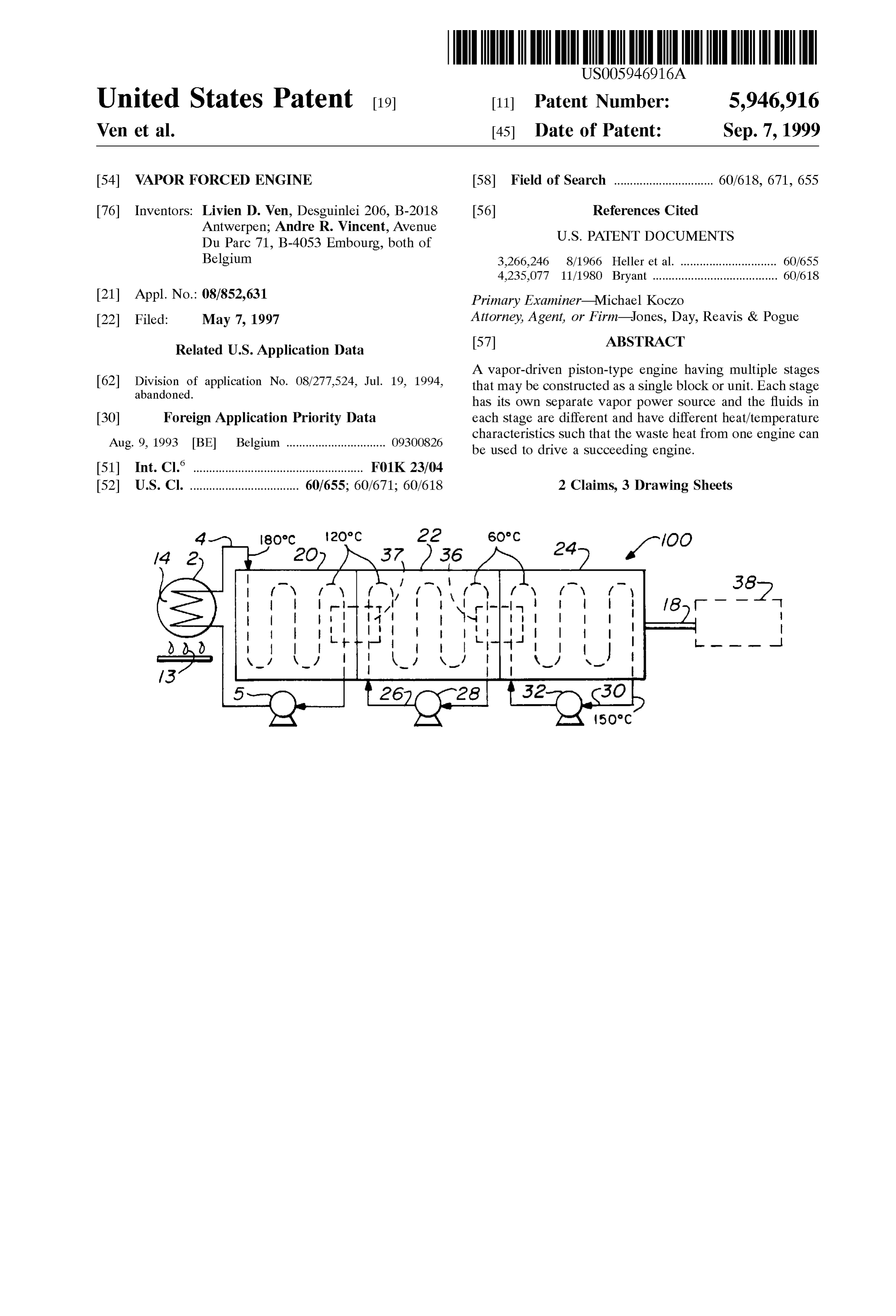
A vapor-driven piston-type engine having multiple stages 62 Division of application No. 08/277,524, Jul. 19, 1994, that may be constructed as a single block or unit. Each Stage abandoned.
has its own Separate vapor power Source and the fluids in 30 Foreign Application Priority Data each Stage are different and have different heat/temperature Aug. 9, 1993 BE Belgium ............................... O930O826 characteristics Such that the waste heat from one engine can be used to drive a Succeeding engine.
(51) Int. Cl. ............................................... F01K 23/04 52 U.S. Cl. .................................. 60/655; 60/671; 60/618 2 Claims, 3 Drawing Sheets
Page 2
Drawing sheet — no readable text.
Page 3
Drawing sheet — no readable text.
Page 4
Drawing sheet — no readable text.
Page 5
WAPOR FORCED ENGINE efficiency figures Stated in this patent, the use of Such high temperatures and low pressures must have a detrimental
This is a divisional of application Ser. No. 08/277,524 influence on the overall efficiency of the turbine. filed on Jul. 19, 1994 now abandoned. In U.S. Pat. No. 4,700,543 to Krieger et al., a plurality of
BACKGROUND OF THE INVENTION
independent, closed Rankine cycle power plants, each of which has a vaporizer and is operated by Serially applying a 1. Field of the Invention medium or low temperature Source fluid to the vaporizers of The invention relates in general to a vapor-driven piston the power plants for producing heat-depleted Source fluid. type engine and in particular to a vapor-driven piston-type The heat-depleted source fluid is applied to all of the engine that has a first fluid therein that receives heat from a preheaters in parallel. The power plants are shown to be heat Source to vaporize the fluid and drive the piston engine turbines.
and which includes therein a Second closed fluid path in heat Thus, there is a significant need in the art for a vapor eXchange relation with the first fluid path to increase the driven piston-type engine that has high efficiency and which efficiency of the engine. In a still further embodiment, a 15 operates at relatively low temperatures. plurality of the efficient vapor-driven piston-type engines are SUMMARY OF THE INVENTION coupled one to another in different closed circuits whereby the fluid in the first closed circuit in a Second or Subsequent The present invention aims to remedy these disadvantages Vapor-driven piston-type engine is heated by the first vapor and to provide a highly efficient vapor-force piston device driven piston-type engine or by the fluid flowing through it. whose operation is relatively inexpensive and which, in a 2. Description of Related Art particular embodiment, enables practical use to be made of A conventional vapor force piston device contains a temperature Sources at a relatively low temperature, thus Vaporizable fluid, an evaporator for vaporizing the fluid, the enabling the use of inexpensive fuels. Vapor piston machine and a closed circuit in which the The results are achieved with the present invention evaporator and the vapor piston machine are interposed for 25 because the fluid used in the machine is a fluid with an the transport of the fluid. Such a conventional vapor force atmospheric evaporation temperature lower than 50 C. and device of this Sort may be a Steam power plant which uses with Such evaporation characteristics that even at a low water as a fluid. The evaporator is the Steam generator and temperature, high pressure vapor is obtained. Suitable fluids the vapor machine is a Steam engine with pistons or a steam are, in particular, those fluids which are used in cooling turbine driving a current generator. installations Such as fluorohydrocarbons or an equivalent However, water evaporates at 100° C. under atmospheric alternative. A very well-suited fluid, therefore, is 1,1- preSSure. In order to obtain a good efficiency, over-heated or dichloro 2.2.2-trifluoroethene.
Super-heated Steam at an even far higher temperature is According to a special embodiment of the invention, the required. This implies that for the evaporation in the Steam evaporator is a heat eXchanger having the above-mentioned generator, high quality and quantities of fuel are required. It 35 fluid as a Secondary fluid and another liquid as the primary further implies that the device cannot work on heat alone at fluid. The heat eXchanger may, in a practical Sense, form the a relatively low temperature even though it may be available radiator of an explosion engine, Such as an automobile in large amounts. Thus the Supplied energy is relatively engine, whose coolant forms the primary fluid. expensive. Alternatively, the heat eXchanger may be a device that In U.S. Pat. No. 3,218,802 and issued in the name of D. 40 eXchanges heat between a hot gas and a fluid or may be a R. Sawle, a binary vapor power plant includes a Sulfur cycle boiler that is filled with the primary fluid and that is heated consisting of a heat Source 10 which heats and vaporizes by a heat Source. The heat Source may be a burner, an electric Sulfur, a first stage Sulfur heat engine 12 which converts the resistor, Solar energy, and the like. heat in the vapor into kinetic energy, and a heat eXchanger In another embodiment of the invention, the evaporator 14 that receives the partially cooled Sulfur and removes the 45 itself contains the heat Source. This heat Source may be a remainder of the heat. The heat exchanger 14 heats the fluid burner, a reflective mirror in a Solar energy installation or an in conduits 37, 41, and 43 to convey Steam to a Second Stage electric resistor. It may also be an explosion engine, Such as heat engine 16. Similar Systems have been employed at an automobile engine, wherein the fluid Serves as a coolant petrochemical plants that use ethylene-oxide reactors. The for the automobile engine. In case the heat is Supplied by reactors are cooled by a high temperature, low preSSure fluid 50 Such automobile engine, the vapor machine can be con (diphyl fluid). This fluid is sent to a heat exchanger to nected to the power output shaft of the engine or may be produce the Super-heated Steam. The Steam was used in a formed in one and the same engine block with the explosion Steam turbine to compress ethylene gas. This System has engine and thus both the vapor machine and the explosion very difficult problems to overcome since using Sulfide, engine are coupled to the Same power output shaft. Sulfur, phosphorus or even Sodium is excluded because Steel 55 In accordance with another embodiment of the invention, is hydrogen permeable and hydrogen with the above mate the vapor force device contains more than one vapor rials will give Severe problems. This is a very high tempera machine which are erected one after the other in the form of ture device with Saturated sulfur vapor at 1260 F. a cascade. In Such case, the plurality of vapor machines may In U.S. Pat. No. 4,070,862 issued to Doerner et al., a be coupled to each other in closed circuits whereby the fluid turbine in power station plants is provided with two different 60 in the fluid circuit for the Second or Subsequent vapor fluids such as water and H. One of the problems is the machine is heated by the first or preceding vapor machine leakage from one turbine Site to the other. The invention is and/or by the fluid running through it. Again, in Such case, a choice of two liquids where the Second liquid has a lower the fluids in the Successor circuits may be different, Such as boiling point than the first liquid and returns the vapor each having a different temperature function. condensate (linkage) to the boiler. The two liquids have low 65 Thus, it is an object of the present invention to provide a pressures compared to their temperatures at 800 F. with 34 Vapor force engine that has a primary fluid therein that is PSIA and 450° C. at 51 PSIA. Athough there are no heated by the waste heat from an explosion engine Such as
Page 6
an automobile engine that has a fluid circulating there The invention also relates to a low temperature vapor through to cool the explosion engine. force engine comprising n vapor driven piston-type engines It is also an object of the present invention to provide an where ne2, each vapor-driven piston-type engine having a explosion engine and a vapor force engine within a common Vapor fluid inlet and a fluid outlet, a first heat eXchanger housing and both having pistons coupled to a common coupled to the vapor inlet and the outlet of a first one of the output drive Shaft, the explosion engine being cooled by a Vapor-driven piston-type engines for receiving the fluid from first fluid that is heated to a first temperature and the vapor the fluid outlet of the first one of the vapor-driven piston force engine being driven by a Second fluid having a type engines, a heat Source for Selectively coupling to the Vaporizing characteristic that is at a lower temperature than first heat eXchanger to vaporize the fluid therein at a tem the first temperature of the cooling fluid of the explosion perature less than 180° C. (356°F) for powering the first one engine and that is coupled in heat transfer relationship to the of the vapor-driven piston-type engines, a Second heat fluid of the explosion engine to be vaporized and drive the eXchanger for receiving the fluid output from the first Vapor engine. Vapor-driven piston-type engine at a temperature of less than It is still another object of the present invention to provide 120° C. (248 F.), the vapor fluid of the second vapor-driven a vapor engine and an explosion engine mounted in the same 15 piston-type engine being coupled to the Second heat housing and wherein the vapor engine has a first fluid therein eXchanger for being vaporized at a temperature of less than that cools the explosion engine which vaporizes it to drive 120° C. (248 F) to drive the second vapor-driven piston the vapor engine. type engine, and each Succeeding vapor-driven piston-type It is still another object of the present invention to mount engine having a heat eXchanger between it and the preceding a plurality of different vapor machines in the form of a Vapor-driven piston-type engine and having a vapor fluid cascade wherein the input fluid to the first vapor machine is therein that will vaporize and drive the Succeeding vapor of a temperature and character to drive the pistons therein driven piston-type engine at a temperature leSS than the and the waste temperature of the output fluid thereof is Such temperature of the output fluid of the preceding vapor-driven as to heat a Second fluid in the Second engine to vaporize it piston-type engine.
and drive the Second vapor piston engine, the waste tem 25 perature of the fluid output from the Second vapor engine BRIEF DESCRIPTION OF THE DRAWINGS being Such as to transfer heat to a third fluid in a third vapor These and other objects of the present invention will be piston engine to vaporize the third fluid and drive the third more fully understood when taken in conjunction with the piston engine and then transmit the fluid output of the third following DETAILED DESCRIPTION OF THE DRAW engine back to a heater to vaporize the fluid to begin the INGS in which:
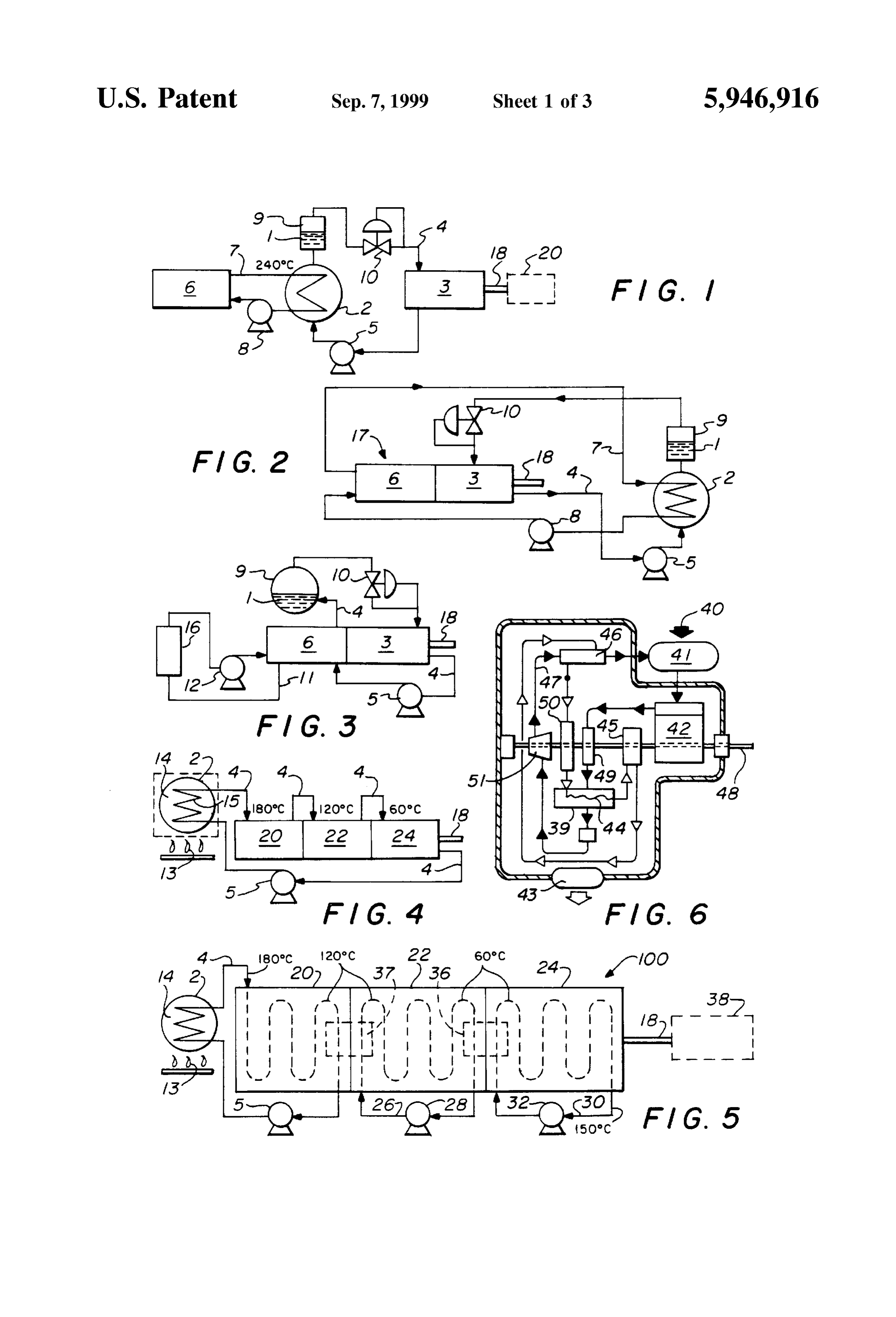
cycle all over again. FIG. 1 represents a block diagram of a vapor force device It is also an object of the present invention to cascade a according to the invention;
plurality of different vapor machines Such that they are FIG. 2 represents a block diagram analogous to that in mounted in Separate closed fluid circuits whereby a different FIG. 1 but with reference to another embodiment of the fluid flows in each vapor machine and which receives its 35 invention where the heat Source is an explosion-type engine input heat from the waste heat of the preceding vapor contained within the same housing as the vapor engine; machine.
It is an important object of the present invention to utilize FIG. 3 is a block diagram analogous to that in FIGS. 1 and a vapor-driven piston-type engine that has a first fluid for 2 but with reference to yet another embodiment of the invention wherein the fluid that is vaporized and drives the driving the pistons and a Second fluid circulating in a closed 40 Vapor loop within the engine in heat transfer relationship with the piston-type engine is the cooling fluid for the
first fluid to thereby increase the efficiency of the vapor with the vapor-driven engine that is housed in a common housing drive piston-type engine. piston-type engine; Thus, the invention relates to a vapor force engine con FIG. 4 is a block diagram of another embodiment of the taining an vaporizable fluid, an evaporator for vaporizing 45 present invention in which the fluid providing the heat Said fluid, a piston engine in a closed fluid circuit in which Sources for a plurality of cascaded vapor-type engines passes the fluid is vaporized, is coupled to the piston engine for through all of the cascaded engines, entering each engine at work, is condensed, and is returned to the evaporator, the one temperature Sufficient to vaporize a fluid therein, exiting improvement comprising a vapor-driven piston-type engine the first engine at a temperature to vaporize the Second fluid having a vapor input and a fluid output, a heat eXchanger 50 in the Second engine, exiting the Second engine at a still having an input and an output coupled to the engine, the heat lower temperature sufficient to vaporize a third fluid in the eXchanger receiving a low temperature fluid from the engine third vapor-type engine and coupling the fluid back to the fluid output and generating a vaporized fluid for the engine heater for revaporizing the fluid and commencing the cycle Vapor input for driving the piston engine, an explosion OVer, engine cooled by a circulating fluid and Serving as a Source 55 FIG. 5 is a block diagram of still another embodiment of of heat, a radiator on Said explosion engine for cooling the the invention in which each vapor machine has its own circulating fluid and forming the heat eXchanger Such that closed fluid circuit with the temperature of the output fluid the explosion engine circulating fluid is a primary fluid and in one engine being Sufficient to vaporize a fluid in the the low temperature fluid for the vapor force engine is a Succeeding engine and all of which engines are coupled to secondary fluid that flows through the radiator in heat 60 a common Shaft for providing an output; eXchange relationship with and is vaporized by the heat of FIG. 6 is a Schematic diagram of a Baudino vapor-driven the primary fluid to drive the vapor piston engine, and the piston-type engine that has two closed fluid circuits and that low temperature Secondary fluid having an atmospheric provides high efficiency;
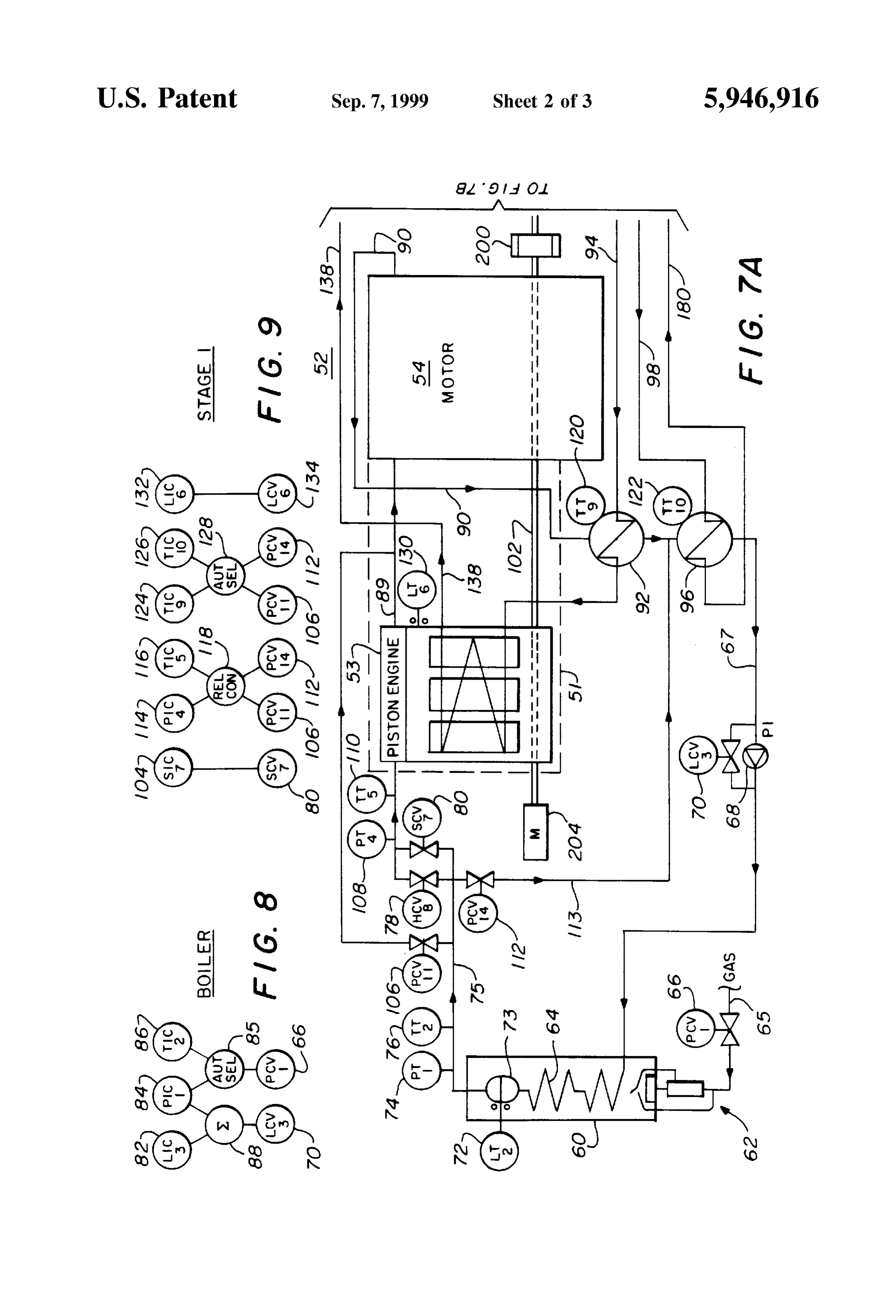
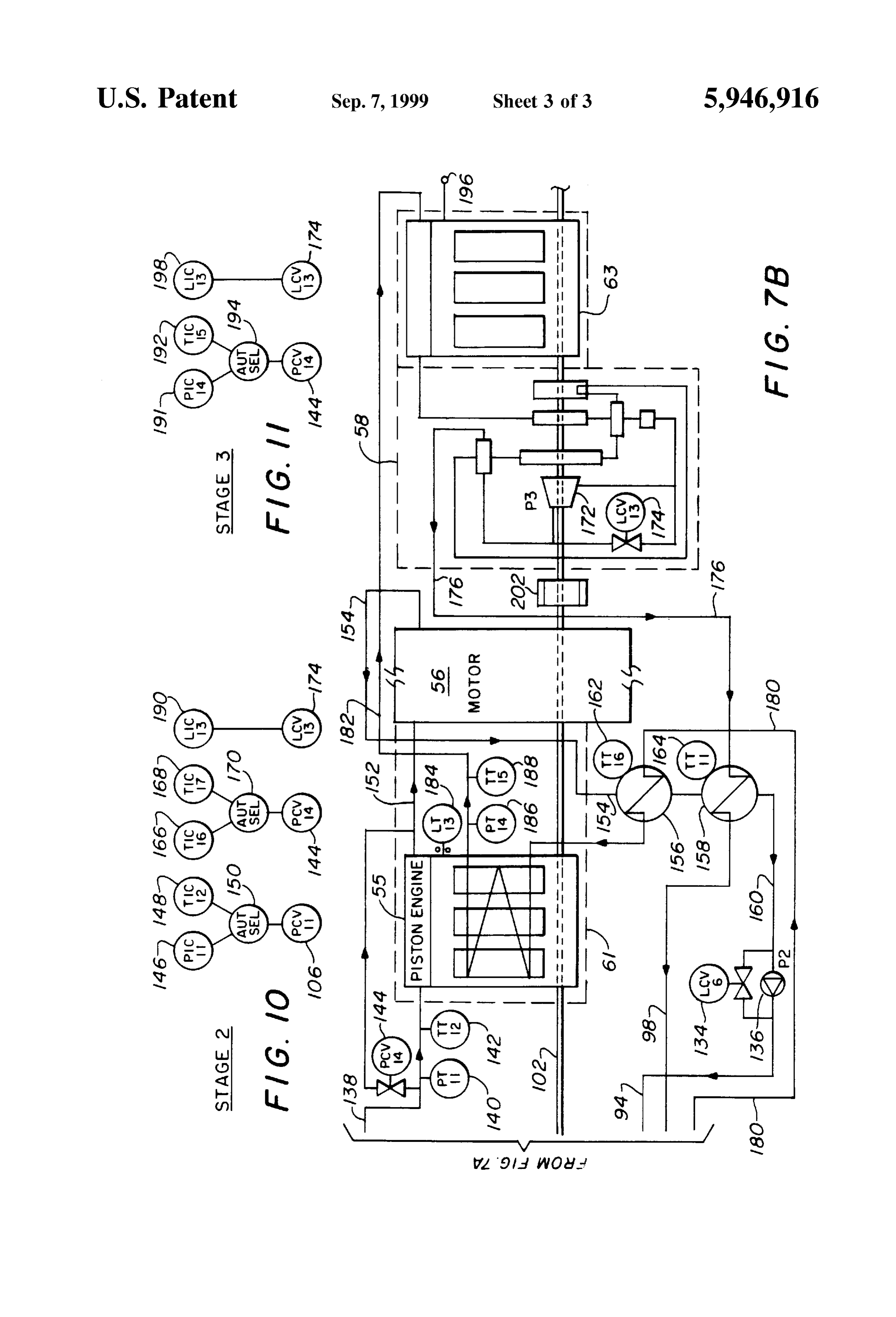
evaporation temperature less than 240° C. (464 F) and FIGS. 7A and 7B are block diagram representations using having evaporation characteristics Such that high pressure 65 a vapor force piston type engine Similar to that in FIG. 5 Vapor greater than 10 bar is provided to the vapor input of except illustrating the details of each vapor engine and the vapor driven piston-type engine. Baudino motor all coupled to a common shaft; and
Page 7
S 6
FIGS. 8, 9, 10 and 11 are each associated with FIG. 7 to tage. Thus the heat of the explosion engine 6 in FIG. 1 which explain the pressure and temperature controls thereof. is otherwise largely lost to the atmosphere can be put to use. DETAILED DESCRIPTION OF THE DRAWINGS AS Stated, in the vapor force device represented in FIG. 1, the evaporator 2 is the heat eXchanger or radiator of an
The novel vapor force device shown in FIG. 1 includes a explosion engine 6 which may be, for example, the radiator Vaporizable fluid 1, an evaporator 2 for vaporizing the fluid, of an automobile or other vehicle, which, instead of being a vapor driven machine 3 which has pistons driven by the cooled with air, is cooled by means of the vapor force engine Vapor, and a closed fluid path 4 in which the evaporator 2 fluid 1 circulating in the closed path 4. The cooling water and the vapor machine 3 are mounted for the transport of the which is pumped through the cooling path 7 of the engine 6 fluid 1. In the closed fluid path 4, upstream of the evaporator by means of the pump 8, and which has a temperature of 2, is mounted a pump 5. The evaporator 2 may in fact be the about 80 C., forms the primary fluid. The fluid which is radiator of a conventional explosion-type engine 6, Such as pumped through the closed path 4 by means of the pump 5 an automobile engine, in which the fluid, Such as water, forms the secondary fluid which is heated until it essentially flows in closed path 7 through the heat eXchanger or radiator reaches the above-mentioned temperature and thereby 2 and is pumped by means of pump 8 back to the explosion 15 evaporates. Downstream of the evaporator 2 is mounted an engine 6 to continually cool the engine. The heat of the fluid expansion tank 9 in which the evaporated Secondary fluid is in closed circuit 7 as it exits from the explosion engine 6 to collected and non-evaporated fluid is collected. Downstream the evaporator 2 may be approximately 240 C. The fluid in thereof is mounted a pressure regulating valve 10 in the the vapor-driven piston-type engine 3 may be of a type that circuit 4. Saturated or preferably Super-heated vapor under vaporizes below 240 C. Such that it will be vaporized by the high pressure is obtained in the evaporator 2. AS indicated heat of the liquid in closed path 7 from the explosion engine above, when tetrafluoroethene is used as the Secondary fluid 6. Thus the invention is characterized in that the fluid 1 is not 1 in closed circuit 4, a pressure of 26 bar can be obtained at water, but is a medium which can be easily evaporated and the outlet of the evaporator 2 at 80° C. The pressure at the whose atmospheric evaporation temperature or boiling tem inlet of the vapor machine 3 can be set by means of the perature is lower than 240 C. and preferably lower than 30 25 preSSure regulating valve 10, for example, as a function of C. in circumstances as will be seen hereafter and which has the pressure in the cylinders of the explosion engine 6. In evaporation characteristics that, even at a low temperature, this way, the explosion engine 6 and the vapor-driven will enable high pressure vapor to be obtained. By “low piston-type engine 3 may be united in one and the same temperature,” it should be understood that such low tem engine block and may possibly even have a common shaft peratures mean below 240 C., as, for example, 240 C., 18 that can be coupled with some driven unit 20 as illus 180° C., 120° C. or 60°, respectively, and the term “high trated in phantom lines in FIG. 1.
preSSure” means a pressure equal to or greater than 10 bar, As illustrated in FIG. 2, the explosion engine 6 and the for example, higher than 20 bar at 120° C., where 1 bar is vapor-driven piston-type engine 3 may be formed in a equal to 1 atmosphere. common housing 17. The operation of the device is similar Fluids which meet these conditions and which are thus 35 to that disclosed in FIG. 1 wherein the cooling water of the Suited to be used in the device are those fluids which are used explosion engine 6 in closed path 7 passes through evapo in cooling installations Such as fluorohydrocarbons. Suited rator 2, is condensed and is pumped back to the explosion fluids are, for example, fluorohydrocarbons from the Series: engine 6 by pump 8. The heat given up in the evaporator 2 trichlorofluoromethane, dichlorodifluor methane, is applied to the fluid 1 which vaporizes in path 4 and is used chlordifluoromethane, 1,1-dichloro 2,2,2-trifluoroethane, 40 to drive the vapor-driven piston-type engine 3. The con 1,1-dichlor-1-fluorethene, 1-chloro-1,1-difluorethene, 1,1,1, densed fluid at the output of the vapor-driven engine 3 is 2-tetrafluorethene and difluoromethane. Further, Substitutes pumped back to the evaporator 2 by the pump 5 where the such as dichlorotrifluoromethane (for example, KLEAF123 process is repeated. Again, an expansion tank 9 may be of ICI) and tetrafluoroethene (for example, KLEA 134a of placed in the line.
ICI) are interesting. The first mentioned Substance has an 45 In the embodiment according to FIG. 3, the evaporator 2 atmospheric boiling temperature of 27 C. and a critical is not the radiator of the explosion engine 6 but is the temperature of 183 C. under a pressure of 36 bar, whereas explosion engine 6 itself which implies that the explosion the last mentioned Substance has a boiling temperature under engine 6 is mounted in the closed fluid path 4 and the fluid atmospheric pressure of -26 C. but evaporates at 80 C. 1 forms the coolant of the explosion engine 6. Thus, as the under 26.3 bar and at 100° C. even under 39.7 bar. The 50 fluid in closed path 4 is pumped by pump 5 through the critical temperature of this substance is 101° C. under a explosion motor 6, it cools explosion engine 6, is vaporized pressure of 40.5 bar. in the process and is coupled through expansion tank 9 to The vapor is Supplied in an analogous manner as Steam to preSSure valve 10, and thence to the vapor-type engine 3 for a vapor machine with pistons driven thereby. In the vapor driving shaft 18. Both the explosion-type motor 6 and the machine 3, there is a pressure drop. The fluid, under this 55 Vapor-driven piston-type engine 3 may be coupled to the lower preSSure, may have a liquid form and is again pumped common shaft 18 to drive the shaft 18. A bypass feeder loop to the evaporator 2 by means of the pump 5 as explained 11 with a pump 12 and a cooler 16 therein is connected to earlier. When the temperature in the evaporator 2 is higher the explosion engine 6 So as to cool off the fluid 1 in closed than the evaporation temperature under the given pressure path 4 in case of a default.
for the vapor machine fluid, a Super-heated vapor is obtained 60 FIG. 4 discloses still another embodiment of the novel and preferably slightly Super-heated vapor is produced in the Vapor driven engine in that the heat for the evaporator 2 is evaporator in order to avoid condensation in the vapor not Supplied by an explosion engine but by a heat Source machine 3. Such Saturated or Super-heated vapor is already such as a burner 13 that heats the operating fluid in fluid path obtained, thanks to the Specially Selected fluid, at relatively 4, by means of a fluid 14 in the evaporator 2 either directly low temperatures, Such that the low-temperature heat 65 or indirectly, as represented in FIG. 4. In the latter case, the Sources, which are abundantly available but cannot be easily evaporator 2 forms a heat exchanger with a boiler filled with put to use in an efficient manner, can be used to an advan a fluid 14 which forms the primary fluid and a pipe or fluid
Page 8
conduit 15 extending through the boiler and which is part of driven piston-type engine 22. This heat can be transferred to the fluid path 4 and through which the operating fluid flows the third vapor engine 24 which is supplied to the third as a Secondary fluid. In this case, the fluid in closed path 4 fluorohydrocarbon, or working fluid, known as R11. This enters the first vapor-driven piston-type engine 20 at a fluid vaporizes at or below 60° C. temperature and drives the temperature, for example, of 180° C. which will drive the third engine 24 and exits the third engine 24 at approxi piston-type engine 20 and vaporize a first fluid in a first mately 15 C. In FIG. 4, the fluid out of the third engine 24 closed System in vapor-driven piston-type engine 20 Such as is transferred back to the evaporator 2 where it is heated disclosed in relation to FIGS. 1 and 2. The primary fluid in again to 180° C. and the cycle is repeated. However, in FIG. closed fluid path 4 that exits the first vapor-driven piston 5, each of the Separate fluids in the Second and third engine type engine 20 is at approximately 120° C. and is coupled to 22 and 24 are reheated through the radiators or heat transfer the Second vapor-driven piston-type engine 22 in a heat devices 36 and 37.
transfer relationship therewith. A second fluid flows in a If the fluid used as the first fluid is one that can be heated closed fluid path within the Second vapor-driven piston-type engine 22 that vaporizes at a temperature less than 120° C. to about 240° C. and that cools off to about 180° C. after and thus drives the Second vapor piston engine 22. The 15 driving engine a vapor-driven piston-type engine, Such vapor piston can be placed between evaporator 2 and the first primary fluid in the closed fluid path 4 exits engine 22 at, for example, approximately 60° C. and is coupled to the third vapor piston engine 20 shown in FIGS. 4 and 5 and thus a Vapor-driven piston-type engine 24 in heat transfer relation unit is obtained with four temperature levels, which, of ship to a third fluid that flows in a closed internal fluid path course, allows for highly efficient use of the heat. Such and which vaporizes at a temperature less than 60° C. to embodiments make it possible to increase the output of an drive the vapor-driven piston-type engine 24. All three explosion engine or other heat Source in a simple manner. engines 20, 22, and 24 are coupled to a common output shaft An efficient engine that can be used as the vapor-driven 18. The fluid in the closed fluid path 4 exits the third piston-type engines discussed in relation to FIGS. 1-5 is Vapor-driven piston-type engine 24 as a liquid which is shown in FIG. 6 in Schematic form. It is known as the pumped by pump 5 back to the evaporator 2 where it is 25 Baudino motor and is patented in France where it carries revaporized and the System repeats itself. publication number FR 2588 645-A1 and national registra FIG. 5 is similar to that illustrated in FIG. 4 except the first tion number 85 15545. (This patent was filed in France on closed fluid path 4 couples vaporized fluid only to the first Oct. 14, 1985 and was made public on Apr. 17, 1987). The Vapor-driven piston-type engine 20 and exits the heat Baudino engine is an anaerobic external combustion engine eXchanger 37, shown in phantom lines, at approximately that uses a combined cycle to co-generate thermal energy 120° C. It gives up essentially all of its heat to the second (cold, heat) and electrical or mechanical energy that can be fluid in the second engine 22. Thus, the first fluid then exits used for any purpose by means of rational utilization of any heat eXchanger 37 as a liquid and is pumped by pump 5 back Source of heat Such as Solar energy, coal, gas, and the like to the evaporator 2, where the process repeats itself. which is first converted into thermal drive power, then into The Second fluid in Second vapor-driven piston-type 35 productive energy. The engine is quiet and clean and engine 22 receives essentially most of the 120° C. heat from operates, using any fuel, in a closed cycle without valves or an ignition System. It can, therefore, meet the Strictest the first stage which is at a Sufficient temperature to vaporize requirements of the new markets requiring the combined use the Second fluid and drive the Second engine. However, after of more than one type of energy Such as heat and electricity, expending this energy driving the Second engine 22, the fluid coupled to the Second heat eXchanger 36 is at approximately 40 and the like by making use of local fuels which existing 60° C. This heat is transferred to the third fluid in the third engines cannot use.
Vapor-driven piston-type engine 24 where the third fluid is This makes it an attractive alternative for developing vaporized and drives the third engine 24. The second fluid countries where it can compete with Steam turbines and fuel output from evaporator 36 condenses to a liquid and is cells as well as a possible option for many industrialized pumped by pump 28 through closed fluid path 26 back to 45 countries Seeking to conquer new markets. The interchange evaporator 37 where the process repeats itself. In like ability of its components make this simple and tough engine manner, the third fluid in the third vapor-driven piston-type a technology that can be adapted to meet requirements as engine 24 exits the engine in fluid path 30 at approximately different as decentralized electricity generation, and Surface 15° C. as a liquid and is forced by pump 32 back to heat or underwater propulsion.
eXchanger 36 where the process again repeats itself. The 50 In this System, the movement of the pistons is not caused three vapor-driven piston-type engines 20, 22, and 24 are in the same way as in conventional engines, as by internal combined in single housing 100 and are all coupled to the combustion of an air/fuel mixture but by a continuous Series same drive shaft 18 for driving some device 38 such as a of actions performed by two active fluids, a working fluid generator. and a reactivating fluid. These two fluids operate in opposite It is to be understood, of course, that the heat Source 13 55 directions of flow inside an enclosure between two heat in FIGS. 4 and 5 could be Solar energy, a hot gas, or any Sources at different temperatures Separated by a two-phase other type of energy desired. adiabatic heat eXchanger. The System receives heat from the The fluids of the three individual fluid circuits are adapted outside atmosphere or an external Source, generates power to the temperatures required. Thus, as a first fluid, the that can be used in mechanical, electrical or a thermal form, aforesaid fluoro-hydrocarbon F123 can be used and this fluid 60 and discharges the residual heat to its cold Source. can be heated to 180° C. in the heat exchanger. In the first The System consists of two separate units, an energy vapor engine 20, this fluid cools off to about 120° C. after conversion unit to convert the energy used to thermal energy driving the pistons therein. The Second fluid in the Second and a fluid tight condensation drive power unit to convert the engine 22 is the above-mentioned hydrocarbon F134a which thermal energy to thermal mechanical or thermal electric is heated to about 120° C. and thus evaporates and is used 65 energy. The thermal energy conversion chambers adapted to to drive the Second vapor-driven piston-type engine 22. It the energy Source used Such as Solar, oils, waste matter, gas, cools off to about 60° C. while driving the second vapor and the like. This energy Source can be used continuously

Page 9
Since the movement of the pistons is not connected to the The choice of fluids determine the design technology of injection and the discharge of combustion gases and this the engine and integrate the following parameters: considerably reduces the quantity of harmful gases Such as temperature, preSSure, heat eXchange Surface, need for Sharp nitrogen oxides, carbon monoxide, and the like discharged decompression that does not require over-heating at the to the outside atmosphere by conventional engines. The engine cylinder inputs, and in particular the thermal loops. condensation chamber contains the engine block and the In theoretical terms, an organic fluid containing fluoro, Such driven Systems including compressors, pumps, AC as fluorinet FC75 in the thermal drive loop, would combine generators, fluid tight enclosed fluid/vapor circulation SyS well with freon R11 in the reactivation loop. tems and thermal reactivation circuits. The engine block The use of the Baudino motor in a multi-stage vapor consists of a number of adjacent cylinderS Such as three, powered engine is illustrated in FIG. 7A and FIG. 7B. The each of which contains a piston to transmit mechanical engine 52 comprises three stages 54, 56, and 58, with each power to the drive Shaft. The compression assembly consists stage formed of a Baudino motor. It should be realized that of a number of radially arranged cylinders, three for each Baudino motor is represented by that motor disclosed example, each of which contains a piston that is thermody in FIG. 6 and is shown in FIG. 7A and 7B with the engine pistons Separated therefrom in order to show the connections namically coordinated with the adiabatic heat eXchanger and 15 between that is integral with the reactivation thermal coils. This dino motor. the engine pistons and the remainder of the Bau ensures optimal coupling of the engine-compressor assem Thus in the first stage, the Baudino motor 54 and bly and operation at constant torque appropriate to the load. the engine pistons 53 are within the same housing as represented by the dashed line 51 Surrounding the engine
The job of the turbine pump is to ensure constant flow rate pistons 53 and extending from the Baudino motor 54. In like circulation and recombination of the working fluid. manner, engine pistons 55 are an integral part of the Baudino Considering now FIG. 6, under the effect of the heat it motor 56 as illustrated by the dashed line 61 surrounding the receives, the working fluid in the high-pressure evaporator engine pistons 55. In like manner, the engine pistons 57 in 41, evaporates thus increasing its pressure and the vaporized the third Stage are formed in the same housing as the fluid can then be used to drive the engine pistons 42 Baudino motor 58 as indicated by the dashed line 63 cyclically in a well-known manner. An external heat Source 25 Surrounding both of them.
40 may provide the heat to the working fluid in the container The heat to drive the process of this engine is shown or high-pressure evaporator 41. The evaporated fluid or gas derived from a Source Such as a boiler 60 with a burner exiting from the pistons 42 is discharged to axial pump 49 system 62 to provide the heat. A fuel such as gas in line 65 and heat exchanger 39 where it transfers a part of its heat in is coupled through a control valve 66 to the burner system closed circulation to the reactivation fluid in fluid path 44. 62. The boiler feed liquid in line 64 in boiler 60 is heated by Heat exchangers 39 and 46 are integrally formed as one unit. the burner System 62 and vaporized. A pump 68 pumps the Thus, gas exiting piston 42 flows through one part 39 in one liquid fluid into the line 64 into boiler 60. A liquid control direction and through the other part 46 in the other direction. valve 70 is in parallel with the pump 68, so that, as will be It is then discharged to the cold Source 43 where it condenses described later, if the valve 70 is opened, the pump 68 is and then passes through turbine pump 51 to the heat 35 essentially disabled to Stop pumping the fluid as needed. exchanger 46 (in the opposite direction than in heat A liquid level sensor 72 detects the level of the liquid in exchanger 39) and returns to its starting point in the closed the expansion tank 73 and the boiler 60. The vaporized container 41 for a new cycle. Thus it should be understood liquid is coupled to line 75, where a pressure sensor 74 and that the heat eXchangers 39 and 46 are part of an integral unit a temperature Sensor 76 give a constant indication of the through which the gas from the pistons 42 passes in the first 40 pressure and temperature of the vapor in the line 75. Thus, direction and then comes back through in the opposite as can be seen in FIG. 8, a computer may be used to control direction as a fluid through the same heat eXchange unit. the operation of the various valves and pumps based upon Thus the fluid in the high-pressure tank 41, at equal mass, the liquid level, pressure, and temperature indicated by the occupies a greater Volume in its vapor phase than in its liquid sensors 72, 74 and 76. Thus, at 82 in FIG. 8, the computer phase. The difference in volume is converted to power that 45 fluid level indicator controller receives the liquid level can be used by the drive shaft 48 and its latent heat is at least indication from sensor 72 and sums that signal at 88 with the partially utilized by the thermal reactivation loop fluid path preSSure Signal received by the pressure indicator controller 44. From the heat exchanger 39, the thermal reactivation 84 that is derived from the pressure sensor 74. The result of fluid is coupled in fluid path 44 to a series of compressors 45 the Summation at 88 is used to control the level control valve and hence by temperature increases, to the adiabatic heat 50 70 that bypasses the fluid pump 68 as described earlier. eXchanger 46. Thus, if the level becomes too high and/or the pressure The discharge of the decompressed active fluid from the increases beyond preset limits, the liquid control valve 70 is engine block cylinders 42 (the decompression is not opened the proper amount and controls the amount of fluid interrupted, but the fluid is decompressed to equilibrium), that pump 68 can continue to supply to the boiler 60. In like and the forced recompression of the fluid in part of the heat 55 manner, as can be seen at step 86 in FIG. 8, the temperature exchanger 46, through which the reactivation fluid low indicator or controller receives the temperature Signal pro preSSure circuit 44 passes, is caused by the axial pump 49 duced by the temperature sensor 76 and is used by the which is integral with the turbine 50. The turbine 50, which computer through auto Selector 85, in conjunction with the is mechanically coupled to the drive shaft 48, is partly driven preSSure indication at Step 84 to control the pressure control by decompression of the compressed reactivation fluid at 46 60 valve 66 that regulates the amount of gas in line 65 being fed and this compensates for a considerable proportion of the to the burner assembly 62. Thus if the pressure and/or the power spent on cyclical recombination of the thermal temperature becomes too high, the amount of gas being fed energy. Depending on the type of application, or the type of to the boiler to produce that temperature is decreased by combustion chamber used to heat the active engine fluid, the partially closing control valve 66. All of these controls by thermal reactivation loop is used either to transfer the heat 65 computer are old and well-known in the art and the operation of the working fluid from the inside of the system to the and control of Such valves based upon temperature and outside or Vice versa. preSSure Signals is not new in and of itself.
Page 10
The vaporized fluid in line 75 is coupled to a manually and providing more heat to the third Stage engine 58 as will adjustable valve 78 which may be similar to a needle valve be explained hereafter.
on a carburetor to allow minimum speed control of the In the fluid return line 94 from the second stage Baudino motor. Speed control valve 80 is manually controlled, such motor 56, there is a pump 136 for pumping the fluid back to as by hand throttle or a foot pedal, but of course, could be the first stage engine pistons 53. The engine pistons 53 Serve controlled by a computer, to provide the amount of vapor as the heat Source for the fluid for the Second Stage Baudino necessary to drive engine pistons 53 of the first stage 54 of motor 56. A fluid level sensor 130 on the piston engine 53 the Baudino motor. Thus the vapor begins to drive the gives an indication if there is a fluid buildup in the piston pistons 53 of the first Baudino motor 54 that begin to rotate engine 53. If so, referring again to FIG. 9, the signal shaft 102 which is commonly coupled to all of the stages. generated by the fluid level sensor 130 is used by the The output vapor from pistons 53 on line 89 is used in the computer through level indicator controller 132 to control a Baudino motor 54 as has been explained previously with valve 134 that bypasses pump 136 to control the amount of respect to FIG. 6 and will not be repeated here. The vapor fluid being pumped in line 94 back to the heat source or output from the Baudino motor 54 on line 90 is coupled to piston engine 53.
a preheater 92 which is a heat eXchanger that also receives 15 Considering the Second Stage, the fluid pumped by pump the fluid on line 94 from the second Baudino motor 56 prior 136 (in FIG. 7B) from the second stage Baudino motor 56 to its being coupled to engine pistons 53 as the cooling fluid. passes through the preheater 92 (in FIG. 7A), where, as In addition, the vapor in line 90 that passes through pre indicated earlier, it receives heat remaining in the fluid heater 92 also passes through a cooler 96 by giving up its output from the first stage Baudino motor 54 on line 90 and remaining heat to the fluid 98 from the third stage Baudino is thus preheated. It is then coupled to the engine piston unit motor 58. Thus, the fluid in line 90 gives up its heat to the 53 of Stage 1 where it serves as the coolant for Stage 1 and, fluid in line 98 and is cooled itself to a liquid in line 67 where in the process, is vaporized and is output from piston engine it is coupled back to pump 68 and the cycle then repeats 53 in conduit 138 to the second stage engine pistons 55 in itself. Thus, as can be seen in FIG. 9, the manual control 104 FIG. 7B. Again, the temperature and pressure of the vapor (or a computer-controlled signal) controls the speed control 25 in conduit 138 is detected by sensors 140 and 142. If either valve 80 to allow more or less vapor to the piston engine 53 the pressure and/or the temperature exceeds predetermined to regulate the engine Speed. limits, then referring to FIG. 10, the computer, through The pressure and temperature of the vapor in line 75 pressure and temperature indicator controllers 146 and 148, entering piston engine 53 is measured by sensors 108 and utilizes the temperature and pressure indications from Sen 110, respectively. Further, a bypass valve 112, when opened, Sors 140 and 142 to control an automatic selector 150 that allows the vapor to pass through conduit 113 to the cooler 96 controls PC valve 144. PC valve 144 is a pressure control for return to pump 68. Thus, referring to FIG. 9, when the Valve that bypasses the engine pistons 55 and couples the pressure and/or temperature as indicated by Sensors 108 and fluid directly into the Baudino motor 56 of the second stage. 110 are too high or outside normal limits, the computer, as Thus again the pressure and temperature of the fluid that is shown in FIG. 9, through pressure and temperature indicator 35 being Supplied to the engine pistons 55 is controlled. Again, controllers 114 and 116, uses the Sensor Signals indicating the vapor output from piston engine 55 in conduit 152 is abnormal pressure and temperature to drive a controller 118 coupled to Baudino motor 56 which functions as described to control the valves 106 and 112. If valve 106 is opened, the previously in reference to FIG. 6. The fluid output of the Vapor can bypass the engine pistons 53 and go directly to the Baudino motor 56 on line 154 is coupled to a pre-heater 156 remainder of the Baudino motor 54 at a higher temperature. 40 and to a cooler (or pre-heater) 158 where the fluid is If the pressure and temperature are Such that they must be condensed in conduit 160 and is coupled back to pump 136 reduced, then Valve 112 is opened to bypass the entire group for recycling through the Second Stage as described previ of Baudino motors and to couple a predetermined portion of ously. Again, temperature Sensors 162 and 164 are provided the vapor back through cooler 96 where it is condensed to a for the preheater 156 and the cooler 158, respectively. liquid in line 67 and coupled back to pump 68. Thus, not 45 Should these temperatures be indicated to be improper, the only the pressure and temperature of the vapor coupled to computer, using temperature indicator and controller 166 the Baudino motor piston 53 are controlled but also the and 168 in FIG. 10, again using automatic selector 170, pistons 53 can be bypassed entirely or a portion of the vapor controls bypass PC valve 144 to allow the vapor to bypass can be coupled back to the cooler 96 to preheat the fluid from the engine pistons 55 and be supplied directly to the Baudino the second and third stages in conduits 94 and 98. 50 motor 56 in the second stage. Thus the output of the second Further, the temperature at preheater 92 is monitored by stage Baudino motor 56 on line 154 would then have an sensor 120 while the temperature at cooler (or preheater) 96 increased temperature for Supplying to the preheater 156 and is monitored by temperature Sensor 122. If the temperature the cooler 158.
at preheater 92 is below a predetermined temperature as It will be noted that the third stage of Baudino motor 58 determined by sensor 120, then, referring again to FIG. 9, 55 illustrates the details thereof and its connection to the piston the computer utilizes that Sensor Signal through temperature engine 63 in the same manner as illustrated in FIG. 6. As indicator controller 124, and an automatic selector 128 to indicated earlier, each of the Baudino motors 54 and 56 are control PC valve 106 and bypass the engine pistons 53 and likewise constructed. It will be noted that internal pump 172 couple the vaporized fluid directly to the Baudino motor 54, in Baudino motor 58 in the third stage is driven by the shaft thus increasing the temperature on the output line 90. In like 60 102. Thus in like manner the pump 68 in the first stage and manner, if the temperature of cooler 96 is below a prede pump 136 in the Second Stage may be part of the Baudino termined level, as determined by Sensor 122, then, referring motorS 54 and 56, respectively, in the same manner as again to FIG. 9, the computer through temperature indicator illustrated in Baudino motor 58 in the third stage. However, controller 126 utilizes that information to operate automatic the pumps 68 and 136 are shown external to Baudino motors selector 128 and control bypass valve 112 to allow more of 65 54 and 56 for ease of explanation. Pump 172 pumps the fluid the vaporized fluid to be conducted directly to the cooler 96 through line 176 out of the Baudino motor 58 to the cooler by bypassing the Baudino motor piston engine 53 entirely 158 in the Second Stage where it picks up Some heat and also
Page 11
helps to condense the output vapor from the Second Stage. It and Second Stages, respectively, can be a part of the Baudino continues to the cooler 96 in the first stage where it does the motor as illustrated by pump 172 in the third stage Baudino Same thing and picks up additional heat. It then returns in motor 58. When pressure indicator 74 and temperature conduit 180 to preheater 156 in the second stage where it indicator 76 in conduit 75 to the first stage piston engine 53 picks up more heat from the output vapor of the Second Stage indicate that the input to the System is brought to the in conduit 154 and then is fed into the piston engine 55 as required pressure and temperature, the computer controls the the coolant therefor. As it is cooling the pistons 55, it absorbs gas Valve 66 as explained earlier to maintain the required heat and is vaporized and exits the piston engine 55 in preSSure. Because of the extremely Small Volume of the conduit 182 where it returns to the input of the piston engine liquid in the boiler, this operation takes only a few Seconds. 63 of Baudino motor 58. There it drives the pistons and then The motor 52 is operated at a minimum speed by the passes through the Baudino motor 58 as explained earlier and repeats the process. adjusted needle control valve 78 as explained earlier and the It will be noted in Baudino motor 58 that a level control desired Speed is controlled by operation of the manual valve 174 bypasses pump 172. A fluid level sensor indicator controlSystem, valve 80 to drive stage one. To have a fast balanced
Stages two and three can be activated quickly by 184 is associated with the second stage piston engine 55 thus 15 controlling providing an indication when a predetermined fluid level is Second Stagebypass to valves 106 in the first stage and 144 in the cause a predetermined amount of the vapor reached in piston engine 55. Then, referring to FIG. 10, the ized fluid to be transferred immediately to the second and signal from fluid level sensor indicator 184 is utilized by the third stages. These bypass valves 106 and 144 are controlled computer and level indication controller 190 to control the by the computer through the pressure controllers 106 in FIG. fluid level control valve 174 in Baudino motor 58 to open the 9 and 144 in FIG. 10. They are also controlled valve 174 and reduce the amount of fluid being pumped by ture controllers 166 in FIG. 10 and 192 in FIG. by tempera 11 based on pump 172. Thus control can be maintained of the fluid level the temperature sensors 122 in the first stage and 158 in the in the piston engine 55 of the Second Stage.
It will also be noted that at the output of the piston engine second from stage at the outlet of coolers 96 and 158, respectively,
Stages one and two.
55 of the second stage, that there is a pressure sensor 186 and 25 Thus the three preSSures applied to Stages one, two and a temperature sensor 188. Referring now to FIG. 11, a three as indicated pressure indicator controller 190 is controlled by the com on the pressures and by associated pressure Sensors are based puter to operate an auto selector control 194 to control the of each stage. The pressure temperatures of the inputs and outputs preSSure control valve 144 at the input to the Second Stage are controlled by the computer control valves 106, 112 and 144 piston engine 55 So as to bypass the engine 55 if necessary to bring the System quickly and thus increase the temperature of the fluid that is in heat into balance. Once the Stages are in balance, then these transfer relationship with the fluid from the third stage in the Valves will be either closed or operated at reduced positions preheater 156 and the cooler 158. Further, fluid level control based on the computer control.
sensor 196 can be attached to the piston engine 57 of the The three Stages are individually powered units and the third stage and referring to FIG. 11, the level indicator 35 forces applied to the shaft are required to be balanced. controller 198, under control of the computer, may operate Therefore the speed of the three units may be different and the level control valve 174 in the Baudino motor 58 to yet mechanically changed by the inner and outer toothed bypass pump 172 and thus maintain the proper fluid level in wheels illustrated by gear boxes 200 and 202 in FIG. 7A and the third Stage piston engine 63. FIG. 7B. By mechanically allowing the toothed wheels to It will be noted that gear boxes 200 and 202 interconnect 40 rotate with respect to each other in a well-known manner, the the shaft 102 of the three stages. Thus gear box 200 connects forces applied to shaft 102 are balanced. The pressures on stages one and two with the shaft 102 while gear box 202 the pistons and in the lines as determined by pressure Sensors couples the Second Stage to the third Stage with the output as indicated, indicate the measurements of the power on shaft 102. The gear boxes are well-known and have inner each shaft from each Stage. A computer compares these and outer toothed wheels in engagement with each other and 45 power measurements in a well-known manner and the heat a respective shaft portion. This will enable forces on the flux from one Stage to another is varied by the computer as indicated to regulate the Speed of Shaft rotation of the three shaft from the three Stages to be balanced even if the Speed Stages.
of the three units is different. When the computer controls the three Stages to achieve Substantially the same Speed, the Because, as indicated earlier, each of the Baudino motors inner and Outer toothed wheels will Simply rotate together. 50 54, 56, and 58 utilize a different fluid that boils at a A description of the operation of the multi-stage vapor temperature less than the output temperature of the preced powered engine 52 shown in FIG. 7A and FIG. 7B is now ing Stage, Stage 2 is receiving Waste energy from Stage 1 and discussed. During start-up, the boiler 60 and burner 62 are Stage 3 is receiving waste energy from Stage 2. In the case Started with a signal that initiates the following Sequence: of needed energy in either Stage 2 or Stage 3 to balance the first, the liquid supply pump 68 is activated and the level of 55 power, Stages 2 and 3 are able to receive additional energy the liquid in the boiler 60 is controlled based on the output through the bypass valves 106 and 144 from stage 1 or stage Signal from level Sensor 72 as indicated previously. At the 2 thus controlling the transfer temperature in the preheaters Same time, the pilot light of the burner System 62 opens a 92 and 156 and coolers 96 and 158. The computer controls Safety valve in a well-known manner and allows fuel in line the Overall heat balance to obtain the optimum working 65 to flow through pressure control valve 66 and is ignited 60 conditions and the cooling temperatures in coolers 96 and by burner 62. The burner 62 is open to a maximum flow rate 158. The coolers of stage 1 and stage 2, 96 and 158 which heats up the System and brings it to the required respectively, are designed Such that the maximum heat flux preSSure. To commence operation, a Starter motor 204 may during heat transfer periods is taken into consideration. Of be connected to and rotate Shaft 102 to begin circulating the course the coolerS may be oversized to avoid cavitation in fluid to the various Stages by the pumps 68 in the first Stage, 65 the pumpS and to safely cool the liquid. 136 in the second stage, and 172 in the third stage. It will be All of the controllers in the systems shown in FIGS. 8, 9, recalled, as stated earlier, that pumps 68 and 136 in the first 10 and 11 by the numerals 82, 84, 86, 104, 114, 116, 124,
Page 12
126, 132, 146, 148, 166, 168, 190, 191, 192 and 198 are all We claim:
proportional-integral controllers that are well-known in the 1. A low-temperature vapor force engine comprising: art and are Such that when the engine functions are noted to at least three vapor-driven piston-type engines, each of have a certain deviation from a Set point as indicated by Said engines having a vapor fluid inlet and a fluid outlet; measurement Signals, the integral function is eliminated. a first heat eXchanger coupled to the vapor inlet and the The integral function comes back into Service whenever it is outlet of a first one of Said vapor-driven piston-type necessary to avoid overshooting in control as is well-known engines for receiving the fluid from said fluid outlet of in the prior art. Said first one of Said vapor-driven piston-type engines, To increase or decrease the power or Speed of the motor, an external heat Source for Selectively coupling to Said the main Supply valve 66 for the fuel is open to Stage 1 and heat eXchanger to vaporize the fluid therein at a tem boiler 60. Because temperature and pressure are always kept constant at the output of the boiler 60, quick acceleration or perature of less than 180°C. (356°F) for powering said heavy tracking at low Speed is possible without perturbation first one of Said vapor-driven piston-type engines, of the combustion. Thus the pressure and temperature of the a Second heat eXchanger for receiving the fluid output fluid from the boiler 60 are controlled separately from the 15 from Said first vapor-driven piston-type engine at a preSSure and temperature that are generated by each of the temperature of less than 120° C. (248 F.); piston engines 53 and 55 for the three stage motors. The a vapor fluid of Said Second vapor-driven piston-type temperature controllers are in auto Select operation to limit engine being coupled to Said Second heat eXchanger for the temperature of the vapors in the coolers and/or preheat being vaporized at a temperature less than 120° C. CS. (248 F.) to drive said second vapor-driven piston-type Thus the present invention relates to a vapor engine that engine; and has multiple Stages but may be formed in a single block. each Succeeding vapor-driven piston-type engine having a Each Stage has it own Separate vapor power Source and the heat eXchanger between it and the preceding vapor fluids in each Stage are different and have different heat/ 25 driven piston-type engine and having a vapor fluid temperature characteristics. In operation, a first fluid passing therein that will vaporize and drive Said Succeeding through the first stage itself is heated by a boiler to a first Vapor-driven piston-type engine at a temperature leSS temperature and passes through the first engine Stage. The than the temperature of the output fluid of the preceding first fluid is pumped back to the boiler by a pump. Stage 1 Vapor-driven piston-type engine. drives an engine Shaft. ExceSS temperature of the first stage 2. A low-temperature vapor force engine comprising: is passed to a cooling fluid from the Second Stage. The three vapor-driven piston-type engines, each of Said cooling fluid of the Second Stage is a Second different fluid engines having a vapor fluid inlet and a fluid outlet, which, at a Second lower temperature, uses the waste heat of the first one of Said engines having a first fluid thereon that the first stage to drive pistons which are also coupled to the is vaporized at less than 180° C. (356 F) at its vapor Same Shaft as the first stage. The Second fluid of the Second 35 fluid inlet and generates waste fluid heat at its fluid Stage passes through an internal heat eXchanger and is outlet of less than 120° C. (248 F.); pumped back to the first Stage for recirculation. A third the Second one of Said engines having a Second different engine Stage has a third different fluid which passes through the heat eXchangers of both the first and Second Stages where fluid therein that is vaporized at less than 120° C. (248 it is heated to a third lower temperature than the Second Stage 40 F.) at its vapor fluid inlet and generates waste fluid heat waste heat and then drives the common shaft after which the at its fluid output of less than 60° C. (140°F); third fluid is pumped back to the Second Stage to be the third one of said engine having a third different fluid recirculated. The three Stages may be mounted one after therein that is vaporized at less than the 60° C. (140°F) another in a cascade form and be constructed in one unitary of the fluid at the fluid outlet of the second engine; engine block. The fluids in the three circuits are all different 45 a heat eXchanger between each two Succeeding ones of and are adapted to vaporize at the temperature required by Said three engines Such that the temperature of the those particular engine Stages. Fluorohydrocarbons may be waste heat from the preceding engine Serves as an employed as the fluids. external heat source for and vaporizes the different fluid While the invention has been described in connection in the Succeeding engine thereby driving each of Said with a preferred embodiment, it is not intended to limit the 50 engines, and
Scope of the invention to the particular forms Set forth, but, a heat Source coupled between Said vapor fluid inlet and on the contrary, it is intended to cover Such alternatives, Said fluid outlet of Said first engine for vaporizing Said modifications, and equivalents as may be included within first fluid and driving Said first engine. the Spirit and Scope of the invention as defined by the appended claims. k k k k k
Provenance
- Collection
- Cited prior art
- Original PDF
- patentimages.storage.googleapis.com →
- Filed
- 1997-05-07
- Pages
- 12
- Method
- pdftotext (the PDF's own text layer) + pdftoppm 300dpi page scans
- Source
- Google Patents bibliographic record
- Granted
- 1999-09-07
- Inventors
- Livien D. Ven; Andre R. Vincent
- Transcribed from
- patentimages.storage.googleapis.com →