patent · US5900330
Power device
4 May 1999
Page 1 — bibliographic record
United States Patent (19) 11 Patent Number: 5,900,330 Kagat agatani (45) Date Oof Patent
54) POWER DEVICE 57 ABSTRACT 76 Inventor: Takeo Kagatani, 308 Mano-Nogizaka The present invention relates generally to a new power 8-12-30 Akasaka Minato-Ku, Tokyo, device. More specifically, it creates hydrogen from Supplied Japan, 107 water and electricity. The hydrogen is then used in combi nation with air in an electrolysis-electrical cell to produce electric power. All of this is accomplished by first Storing the 21 Appl. No.: 08/935,092 hydrogen in a Storage tank or Section furnished for Such 22 Filed: Sep. 25, 1997 Storage, then converting the electricity, via a power converter, to power. Additionally, the power device of the (51) Int. Cl. ................................................ HO1M 8/18 present invention has a special feature whereby the electric 52 U.S. Cl. .................................. 429/17; 429/21; 429/24 power is created from the hydrogen Stored in the above 58 Field of Search .................................. 429/17, 20, 21, mentioned metal alloy hydride Storage tanks. The present 429/24 invention primarily comprises the following four compo nents: (1) an energy Source (i.e., a photovoltaic array to convert Solar energy to electrical power; a windmill to 56) References Cited collect wind power and convert it to electrical power, etc.); (2) a compressor which Supplies the electrolysis-fuel cell
5,187,024 2/1993 Matsumura ............................... 42024 from the atmosphere; (3) a hydrogen storage device (i.e., a 5,250,368 10/1993 Golben et al. ... 429/21 X Solid metallic alloy hydride which Stores hydrogen through 5,506.066 4/1996 Sprouse ..................................... 429/21 a reversible chemical process); and (4) a hydrogen consump 5,612,148 3/1997 Zito ....................................... 429/17 X tion device (i.e., an electrolysis-fuel cell which consumes the hydrogen released from the tanks (using a heat exchange
Primary Examiner Stephen Kalafut process) to provide electricity which powers a motor). Attorney, Agent, or Firm Ward & Olivo 19 Claims, 3 Drawing Sheets
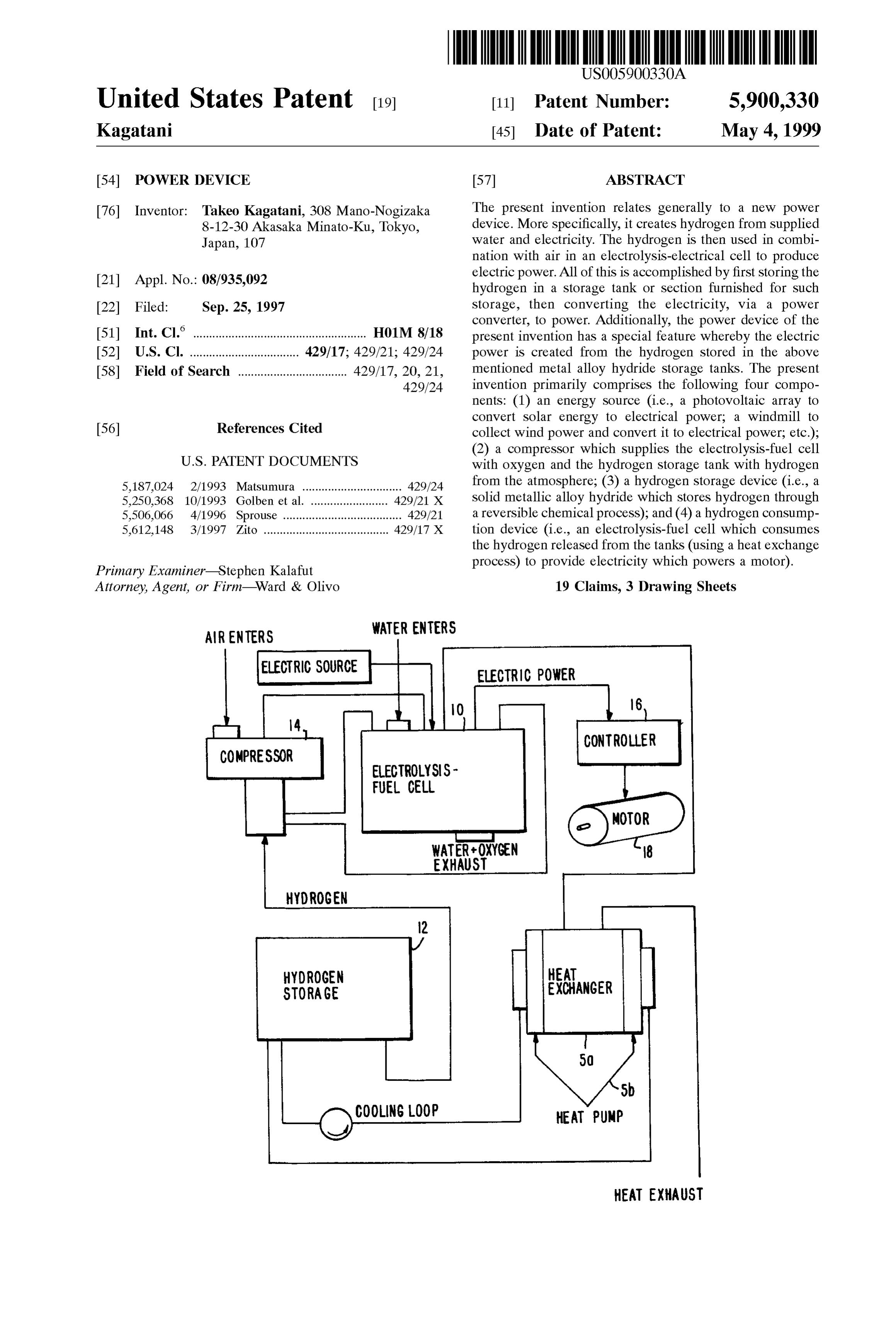
CONTROLLER
COMPRESSOR
ELECTROLYSS
FUEL. CELL
EXHAUST
HYDROGEN
STORAGE EXCHANGER
HEAT EXHAUST
Page 2
Drawing sheet — no readable text.
Page 3
Drawing sheet — no readable text.
Page 4
Drawing sheet — no readable text.
Page 5
POWER DEVICE U.S. Pat. No. 3,577.357 (Winkler) discloses a water
TECHNICAL FIELD OF THE INVENTION
purification membrane composed of block copolymers of
Sulfonated polyvinyl arene block and alpha-olefin elasto
The present invention relates generally to fuel cells and to meric blocks. In one example a styrene-ioSprene-Styrene a power device for use in hydrogen powered cars. More triblock copolymer was Selectively hydrogenated, then Sul Specifically, the present invention discloses a novel power fonated using a premixed SO3/triethylphosphate reagent at device which does not create any environmentally polluting 60° C. for 1.5 hrs. A sulfonated styrene-(ethylene-propylene) exhaust, and is extremely efficient, long lasting, quiet and copolymer was the result. The method provided solid inexpensive. agglomerates of the polymer which were rolled on a mill to BACKGROUND OF THE INVENTION 1O remove water, Swelled in cyclohexane, Slurried in an iso propyl alcohol/water mixture, and coagulated in hot water.
A fuel cell device generates electricity directly from a fuel No membrane was produced, and we have found that Source, Such as hydrogen gas, and an oxidant, Such as polymers produced according to the method of Winkler oxygen or air. It does So by continuously changing the cannot be cast into films.
chemical energy of a fuel and oxidant to electrical energy. 15 Gray et al. Macromolecules 21, 392–397 (1988) dis Since the process does not “burn' the fuel to produce heat, closes a styrene-butadiene-Styrene block copolymer where the thermodynamic limits on efficiency are much higher than the ion-conducting entity is a pendant Short-chain of poly normal power generation processes. In essence, the fuel cell (ethylene oxide) monomethyl ether (mPEG) complexed consists of two catalytic electrodes Separated by an ion with LiCF3SO3 salt and connected through a succinate conducting membrane. The fuel gas (e.g. hydrogen) is linkage to a flexible connecting entity which is the butadiene ionized on one electrode, and the hydrogen ions diffuse block of the triblock copolymer. The ion-conducting entity acroSS the membrane to recombine with the oxygen ions on in the butadiene block is in the continuous phase of the the Surface of the other electrode. If current is not allowed polymer, and the areas populated by the ion-conducting to run from one electrode to the other, a potential gradient is entities do not preferentially touch each other to form built up to Stop the diffusion of the hydrogen ions. Allowing continuous ion-conducting domains. This morphology does Some current to flow from one electrode to the other through 25 not facilitate the ion-conducting properties that are neces an external load produces power. sary for fuel cell operation. The styrene block functions only The membrane Separating the electrodes must allow the as a mechanical Support Structure for the polymer. Moreover, diffusion of ions from one electrode to the other, but must the molecular design chosen by Gray et al. is incompatible keep the fuel and oxidant gases apart. It must also prevent with the working environment of a fuel cell. Because the the flow of electrons. Diffusion or leakage of the fuel or succinate linkage which joins the mPEG to the butadiene oxidant gases across the membrane leads to explosions and backbone and the ether linkages which join the ethylene other undesirable consequences. If electrons can travel oxide units are Subject to cleavage by acid hydrolysis, these through the membrane, the device is fully or partially linkages are unstable in the low pH environment of a fuel shorted out, and the useful power produced is eliminated or cell even for short periods of time. reduced. Ehrenberg et al. U.S. Pat. No. 5,468,574 discloses 35 In the art of battery separators, as exemplified by U.S. Pat. Such a membrane which allows the diffusion of ions, but No. 5,091,275, a number of porous polymers and filled prevents both the flow of electrons and the diffusion of polymer materials are well known. The pores of these molecular gases. This membrane is also mechanically stable. polymers and composite materials are filled with, typically, In constructing a fuel cell, it is particularly advantageous a liquid electrolyte to conduct ions from one electrode to that the catalytic electrodes be in intimate contact with the another in a battery. However, these battery Separator mate membrane material. This reduces the “contact resistance' 40 rials allow the passage of gases, So that fuel cells made with that arises when the ions move from the catalytic electrode them have an unfortunate tendency to explode as the oxygen to the membrane and Vice versa. Intimate contact can be leaks into the hydrogen Side of a fuel cell. facilitated by incorporating the membrane material into the To be useful, the hydrogen gas produced must be Stored catalytic electrodes. See Wilson and Gottsfeld J. Appl. for later use to provide energy when needed. The production Electrochem. 22, 1-7 (1992) 45 of hydrogen from water generally consists of transmitting For reasons of chemical Stability, fuel cells presently electrical energy to electrodes within an electrolyzer to available typically use a fully fluorinated polymer Such as induce an electric potential difference which disasSociates Dupont Nafion Registered TM as the ion-conducting mem water into hydrogen and oxygen. The electrolyzer generally brane. This polymer is very expensive to produce, which contains pure water having as electrolyte of Sodium hydrox raises the cost of fuel cells to a level that renders them 50 ide or potassium hydroxide. These electrolytes are not commercially unattractive. destroyed nor do they need to be replenished during the Ion-conducting polymers are well known. (See Vincent, operation of the electrolyzer. Thus, even though the elec C. A., Polymer Electrolyte Reviews I, 1987). The known trolysis action (the producing of chemical changes by the polymers are, for the most part, Similar to Sulfonated poly passage of an electric current through an electrolyte (a Styrene because of the known ability of Sulfonated polySty 55 nonmetallic electric conductor in which current is carried by rene to conductions. Unfortunately, uncrosslinked, highly the movement of ions, or a Substance that when dissolved in Sulfonated polystyrenes are unstable in the aqueous envi a Suitable Solvent or when fused becomes an ionic ronment of a fuel cell, and do not hold their dimensional conductor)) may take place intermittently, the hydrogen shape. produced can be maintained in Storage and turned back into U.S. Pat. No. 4,849,311 discloses that a porous polymer 60 electrical energy (either by combustion or by use of a fuel matrix may be impregnated with an ion-conducting polymer cell) when desired.
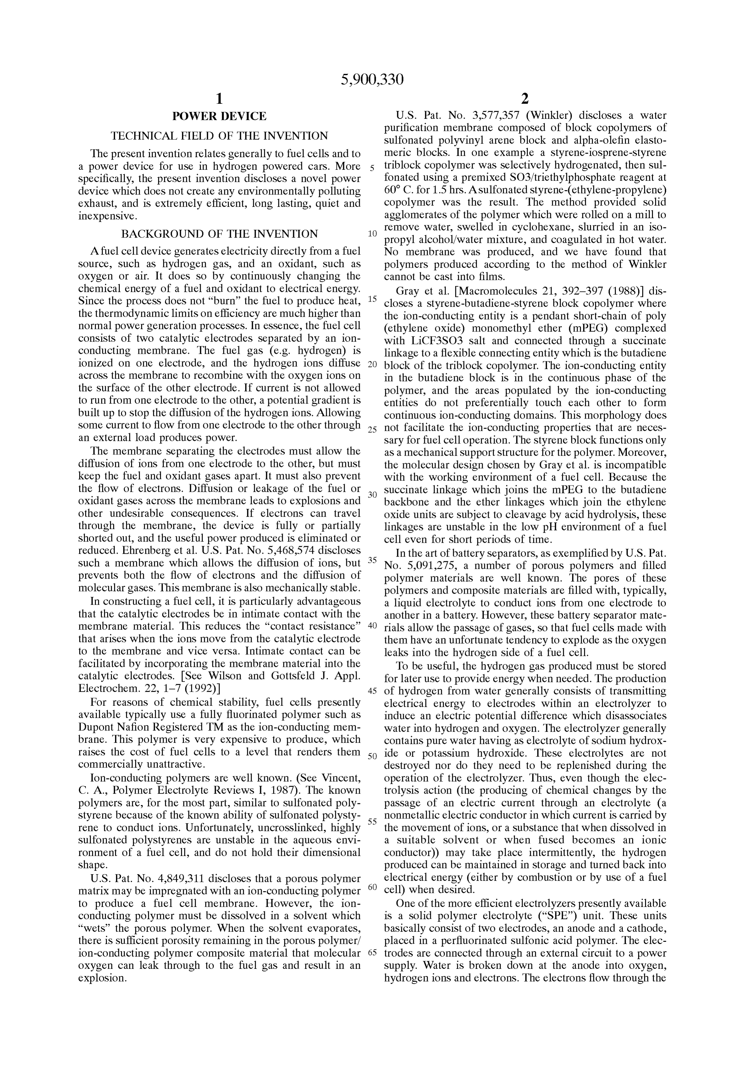
to produce a fuel cell membrane. However, the ion One of the more efficient electrolyzers presently available conducting polymer must be dissolved in a Solvent which is a solid polymer electrolyte ("SPE”) unit. These units “wets” the porous polymer. When the solvent evaporates, basically consist of two electrodes, an anode and a cathode, there is Sufficient porosity remaining in the porous polymer/ placed in a perfluorinated Sulfonic acid polymer. The elec ion-conducting polymer composite material that molecular 65 trodes are connected through an external circuit to a power oxygen can leak through to the fuel gas and result in an Supply. Water is broken down at the anode into oxygen, explosion. hydrogen ions and electrons. The electrons flow through the
Page 6
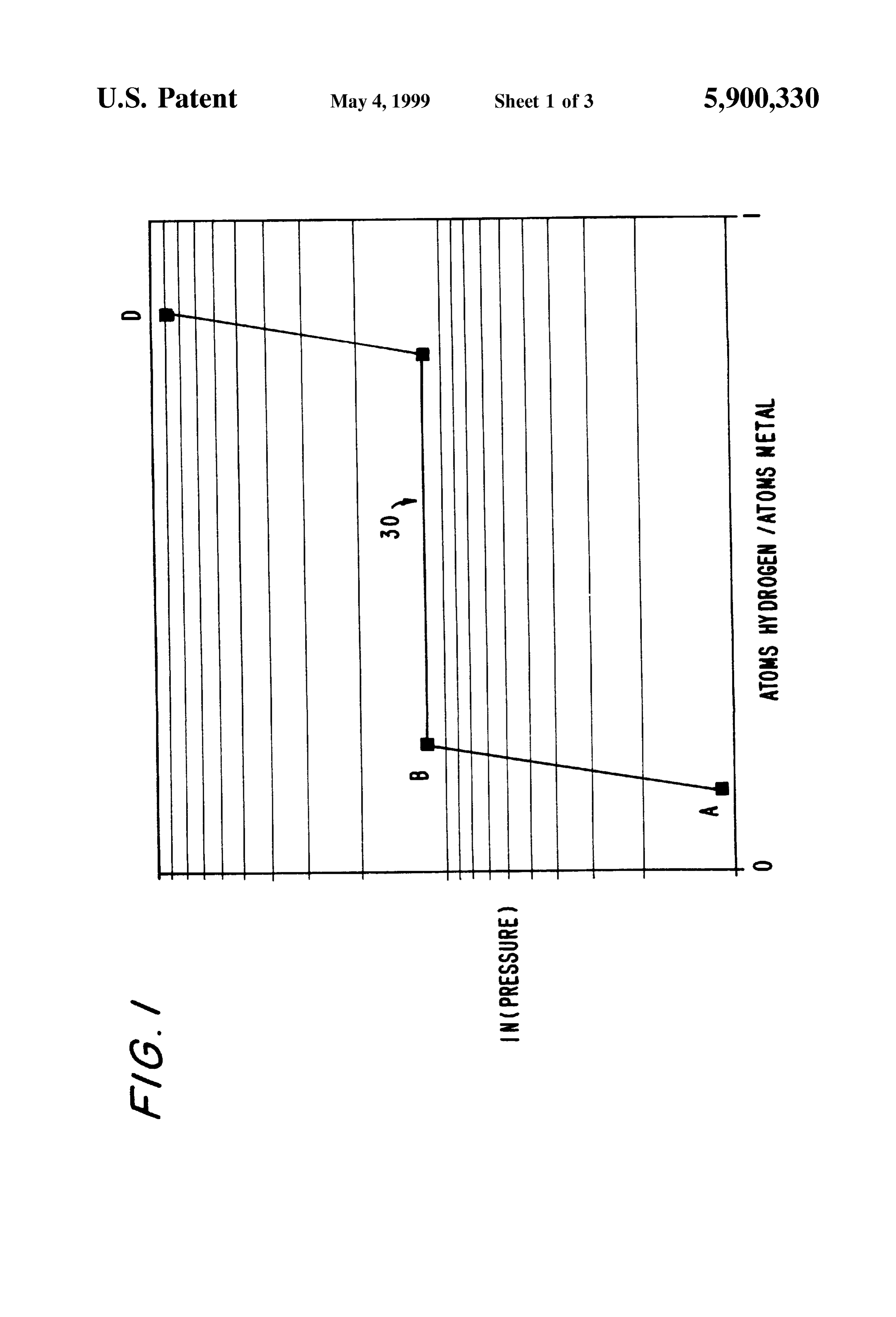
external circuit to the cathode while the hydrogen ions flow The curves connecting points A and B as well as points C through the electrolytic polymer to the cathode where they and D show that for a large increase or decrease in pressure, combine with the electrons and form hydrogen. The equa the amount of hydrogen absorbed or desorbed is Small. tions at the anode and cathode are: In reality, while such isotherms as shown in FIG. 1 might 1 be achievable, most hydrides deviate from this ideal behav
+ O.2 +2e. ior. In addition to the fact that the plateau region slopes and the boundaries of this region are not as well defined, there also exists hysteresis between absorption and desorption and the Overall reaction is: curves. For ideal hydrides, there is no means by which to
measure the composition of the hydride when located along
H.O -> H, -- so, the plateau pressure; but the slope in the isotherm for real metals makes finding the hydrogen to metal ratio as Simple as knowing the temperature and pressure of the hydride.
The by-product of this proceSS is an effluent containing trace The plateau pressure P is related to the absolute tem hydrofluoric acid, oxygen gas and exceSS Water. perature of the reaction, T. by the Vant Hoff equation: SPE electrolyzers are one of the two main types of 15 AH AS
electrolyzers available. SPE electrolyzers are also known as ( PR. T. R
PEM, or Proton Exchange Membrane, for the way in which they split water. The other type, liquid electrolyte (“LE”) where AH is the change in enthalpy, AS is the change in electrolyzers, uses as its electrolyte a Strong acidic or basic
Solution, typically potassium hydroxide. However, there are entropy and R is the universal gas constant. From the Vant a number of advantages that an SPE electrolyzer has over LE Hoff relationship one can determine the charging and dis electrolyzers. The concentration of the Solution in an LE charging preSSures and temperatures of the tank. electrolyzer must be maintained at a constant level for the In recent years, numerous cars have been designed in electrolytic reaction to take place, while SPE electrolyzers order to realize a reduction of pollution and noise. Some of maintain constant concentration over their life. SPE elec these cars have been fueled with nitrogen oxide and trolyzers are also safer, Since they do not require a Supply of 25 hydrogen, resulting in exhaust containing no carbon mon a strong highly corrosive basic Solution as do LE electro oxide. Also, Some of these cars have been getting driving lyZerS. force by loaded Storage cells and motors. The hydrogen gas thus produced is a Storable, However, there are Several shortcomings of the cars transportable, clean, and non-polluting fuel. However, previously made. First, these cars, which were fueled by hydrogen has the fundamental limitation of being difficult to hydrogen, have proven to display reduced driving force due store. Hydrogen has a boiling point of -252.87 C. and a to combusting hydrogen with an internal combustion engine. density of 0.09 grams per liter. This means that in order to Second, regarding the exchange of fuel in the tank which Store hydrogen in reasonable sized tanks, it must be stored Stores the hydrogen and the refilling of this tank, there are either under pressure, at low temperature, or both. currently Serious problems concerning the potential for Unfortunately, it takes energy to create high pressures and 35 dangerous explosions. Third, these cars did not obtain Suf low temperatures. Thus, the overall efficiency and cost ficient driving distances per tank of fuel. Fourth, a car using effectiveness of producing and Storing hydrogen is reduced. a hydrogen fuel cell and a motor could not get enough cell In order to overcome the hydrogen Storage problem, it has capacity with the prior fuel cells Such that it was necessary been found that hydrogen can be stored in a Solid form via to combine many cells in order to get Sufficient power. "rechargeable' metal hydrides, Such as iron-titanium 40 Finally, the prior fuel cells required a very long time to manganese (Fe44Ti55MnS) alloy, mischmetal-nickel alumi charge and their running distances were short. num hydriding (Mn0.97Ni4.5A10.5) alloy, and the like. This It has also been previously Suggested that in order to most can best be described by the reversible chemical reaction of efficiently use a fuel cell System for vehicular propulsion, the a solid metal hydride(Me) with gaseous hydrogen (H2) to System should be, preferably, sized So as to provide Sufficient form a solid metal hydride (MeH x): power, at a useful voltage, for normal continuing operation, 45 or cruising operation, when utilizing air as the Oxidant, and
-Me +H es Me + heat 2 X that during peak loads, pure oxygen should be Substituted for air as the oxidant. This allows the fuel cell system to be sized for normal low power/air operation, but also to provide a
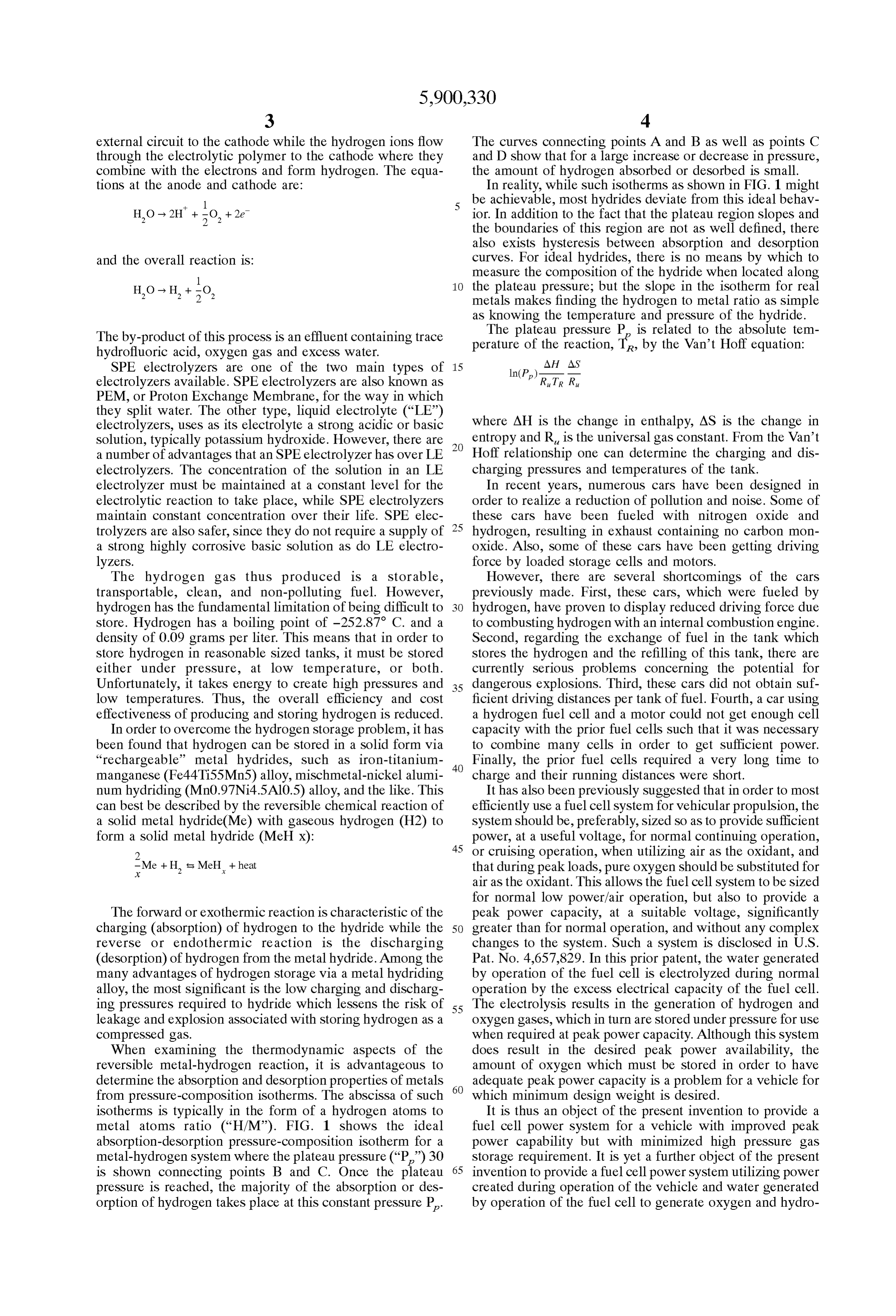
The forward or exothermic reaction is characteristic of the peak power capacity, at a Suitable Voltage, Significantly charging (absorption) of hydrogen to the hydride while the 50 greater than for normal operation, and without any complex reverse or endothermic reaction is the discharging changes to the System. Such a System is disclosed in U.S. (desorption) of hydrogen from the metal hydride. Among the Pat. No. 4,657,829. In this prior patent, the water generated many advantages of hydrogen Storage via a metal hydriding by operation of the fuel cell is electrolyzed during normal alloy, the most significant is the low charging and discharg operation by the exceSS electrical capacity of the fuel cell. ing preSSures required to hydride which lessens the risk of 55 The electrolysis results in the generation of hydrogen and leakage and explosion associated with Storing hydrogen as a oxygen gases, which in turn are Stored under pressure for use compressed gas. when required at peak power capacity. Although this System When examining the thermodynamic aspects of the does result in the desired peak power availability, the reversible metal-hydrogen reaction, it is advantageous to amount of oxygen which must be stored in order to have determine the absorption and desorption properties of metals 60 adequate peak power capacity is a problem for a vehicle for from pressure-composition isotherms. The abscissa of Such which minimum design weight is desired. isotherms is typically in the form of a hydrogen atoms to It is thus an object of the present invention to provide a metal atoms ratio (“H/M”). FIG. 1 shows the ideal fuel cell power System for a vehicle with improved peak absorption-desorption preSSure-composition isotherm for a power capability but with minimized high pressure gas metal-hydrogen system where the plateau pressure (“P”)30 65 Storage requirement. It is yet a further object of the present is shown connecting points B and C. Once the plateau invention to provide a fuel cell power System utilizing power preSSure is reached, the majority of the absorption or des created during operation of the vehicle and water generated orption of hydrogen takes place at this constant pressure P. by operation of the fuel cell to generate oxygen and hydro
Page 7
S 6 gen for use during peak power intervals, but wherein the The present invention primarily is comprised of four effectiveness of the oxidant air is enhanced by enrichment components. First, an energy Source, Such as a photovoltaic with oxygen So as to reduce the amount of Storage capacity array to convert Solar energy to electrical power, a windmill required for peak acceleration requirements. It is yet another used to collect wind power and convert it to electrical power, and further objective of the present invention to provide a and the like. Second, a compressor which Supplies the fuel cell powered vehicle having improved efficacy during electrolysis-fuel cell with oxygen from the atmosphere and operation. Other objects and advantages will become appar hydrogen from the hydrogen Storage tank. Third, a hydrogen ent when considering the following Specific description of Storage device, Such as a Solid metallic alloy hydride which an example of the invention. Stores hydrogen through a reversible chemical process. The present invention provides a novel and useful power Fourth, a hydrogen consumption device, Such as an device which has overcome the problems existing in the electrolysis-fuel cell which consumes the hydrogen released prior hydrogen fuel cell Systems used for electric cars, from the tanks (using a heat exchange process) to provide including but not limited to reducing exhaust pollution. electricity which powers a motor. OBJECTS OF THE INVENTION An important feature of the present invention is matching
the Specifications of the electrolyzer to the hydriding and
The present invention relates generally to a new power dehydriding reactions occurring with the metal hydride to device. More specifically, it creates hydrogen from Supplied allow the System to operate at Sufficiently low pressures water and electricity, which is Stored in a storage tank (near ambient) and thereby eliminate the need for holding furnished for Such storage, So that the hydrogen can be used the System under pressure.
later. An electrolysis-electrical cell then produces electric The hydrogen produced is Stored as a Solid hydride when power from the Supplied hydrogen and air. The electricity not in use, which eliminates the inconveniences and hazards created is then converted to power by a power converter. asSociated with Storing hydrogen as a compressed gas. Additionally, this power device has a special feature Operating the Solid hydride Storage System and electrolyzer whereby the electrical power is created by the hydrogen at low pressures lessens the chance of leakage and Stored in the above mentioned Storage Section. explosion, allows simpler Sealing configurations, allows for Another feature of the present invention is an electrolysis 25 the use of less expensive construction materials, lessens the instrument fuel cell structured with three layers of platinum chance of Structural fatigue, allows for easy assembly of the electrode, multiplex polymer membrane and iridium elec entire System, and eliminates compressor pulsations and/or trode. Vibrations which can cause Structural damage and leakage. Another feature of the present invention is that the Storage A significant advantage of the System is that hydrogen is Section is made of a hydrogen Storage alloy. produced in a steady Supply using only air, water and either Another feature of the present invention is that the power Solar energy, wind power, or the like, which are practically converter contains a motor which acts as a storage cell inexhaustible.
charged with the power created at a fixed rate in the An attractive aspect of the use of photovoltaic energy in electrolysis-electrical cell and which Supplies the necessary the formation of hydrogen fuel is that hydrogen is environ power at time of acceleration. Also, a controller which 35 mentally benign. It can be burned in air without producing controls the charge and discharge of the above mentioned excessive amounts of greenhouse gases or other pollutants Storage cell and controls the rotation Speed of the motor and attributed to hydrocarbon or fossil fuels. Hydrogen can also torque is incorporated in this invention. be used to power a fuel cell to generate electricity directly, Other objects, features, and characteristics of the present with the only by-product being water. The present invention invention, as well as the methods of operation and functions 40 can thus demonstrate the potential of hydrogen fuel as an of the related elements of the structure, will become more alternate Source of energy when produced in this safe and apparent upon consideration of the following detailed clean manner.
description with reference to the accompanying drawings, all of which form a part of this specification. BRIEF DESCRIPTION OF THE DRAWINGS SUMMARY OF THE INVENTION 45 A further understanding of the present invention can be AS discussed previously, this invention relates generally obtained by reference to a preferred embodiment set forth in to a new power device. More specifically, it creates hydro the illustrations of the accompanying drawing. Although the gen from Supplied water and electricity. This hydrogen is illustrated carrying embodiment is merely exemplary of Systems for out the present invention, both the organization and then used in combination with air in an electrolysis method of operation electrical cell to produce electric power. This is accom 50 with further objectivesofand the invention, in general, together advantages thereof, may be more plished by first Storing the hydrogen in a Storage tank or easily understood by reference to the drawings and the Section furnished for Such storage. Next, a power converter following description. The drawing device converts the electricity, which is created in the above the Scope of this invention, which isisSetnotforthintended to limit with particu mentioned electrolysis-electrical cell, to power. larity in the claims as appended or as Subsequently amended, Additionally, the power device of the present invention has 55 but merely to clarify and exemplify the invention. a special feature whereby the electrical power is created For a more complete understanding of the present from the hydrogen Stored in the above mentioned Storage tank. Further, this invention relates to a method and appa in invention, reference is now made to the following drawings ratus for converting energy to hydrogen gas and the Storage which:
of the hydrogen gas in, for example, metal alloy hydride FIG. 1 is a plot showing the ideal absorption-desorption Storage tanks. 60 preSSure-composition isotherm for a metal-hydrogen SyS In an effort to overcome the numerous disadvantages tem.
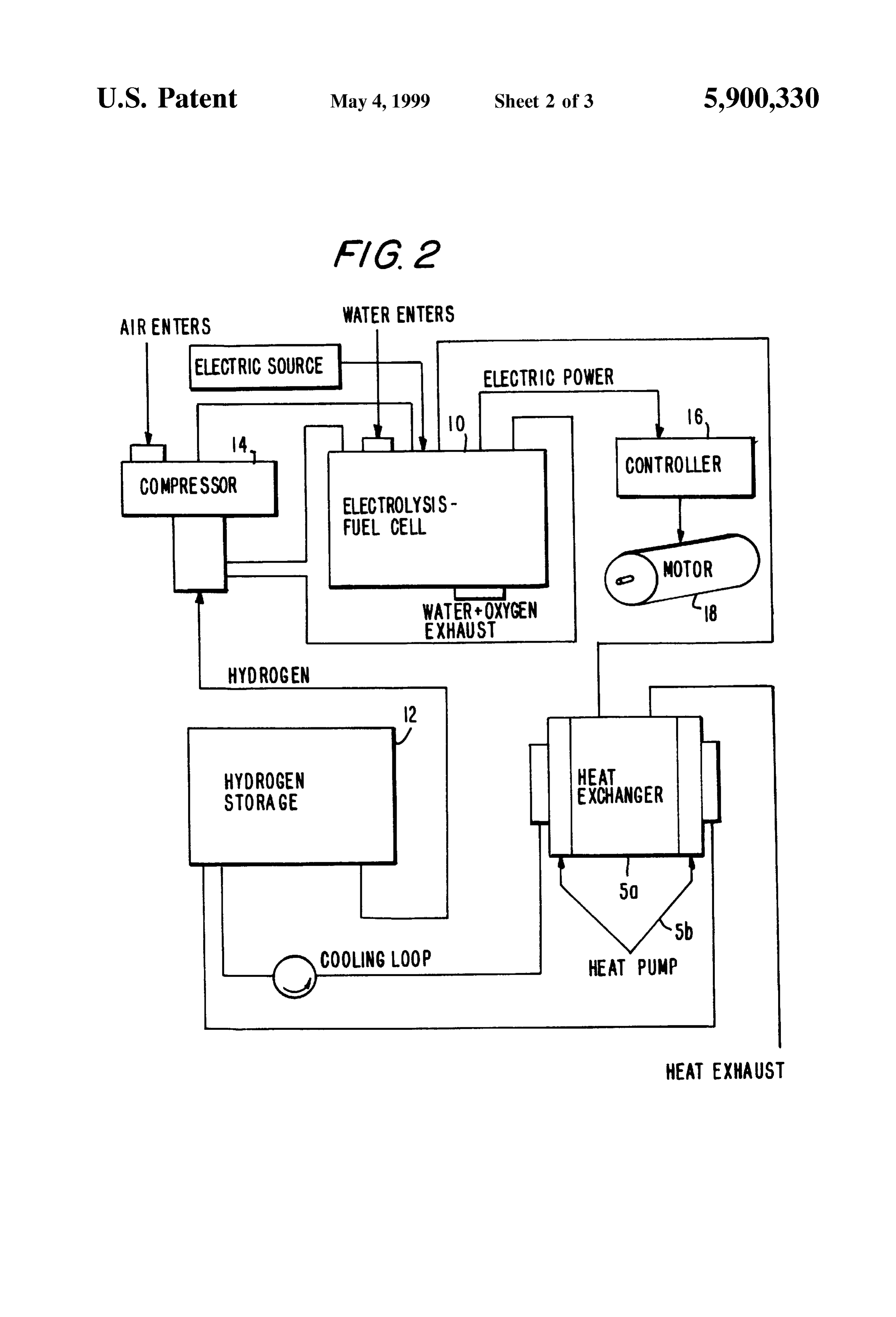
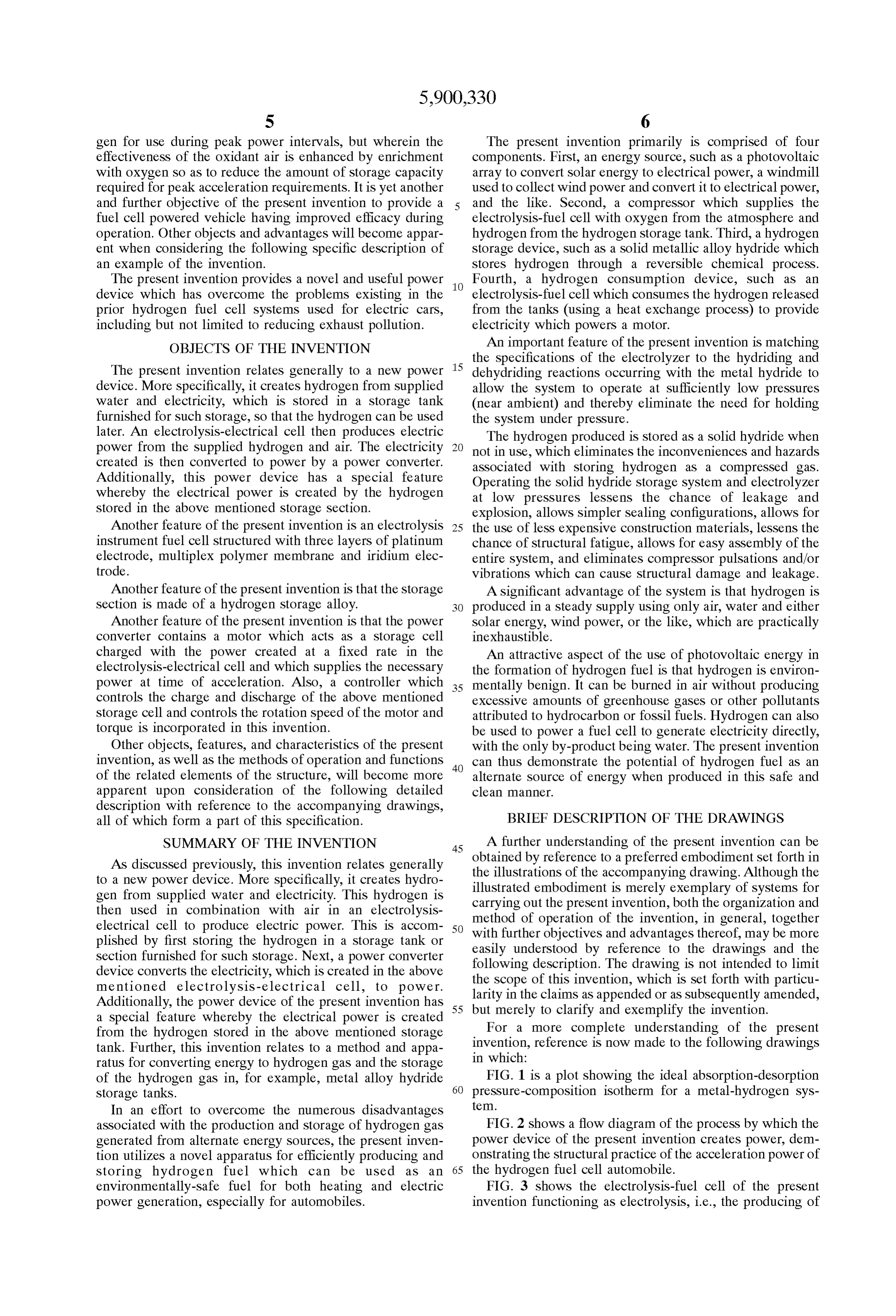
asSociated with the production and Storage of hydrogen gas FIG. 2 shows a flow diagram of the process by which the generated from alternate energy Sources, the present inven power device of the present invention createS power, dem tion utilizes a novel apparatus for efficiently producing and onstrating the Structural practice of the acceleration power of Storing hydrogen fuel which can be used as an 65 the hydrogen fuel cell automobile.
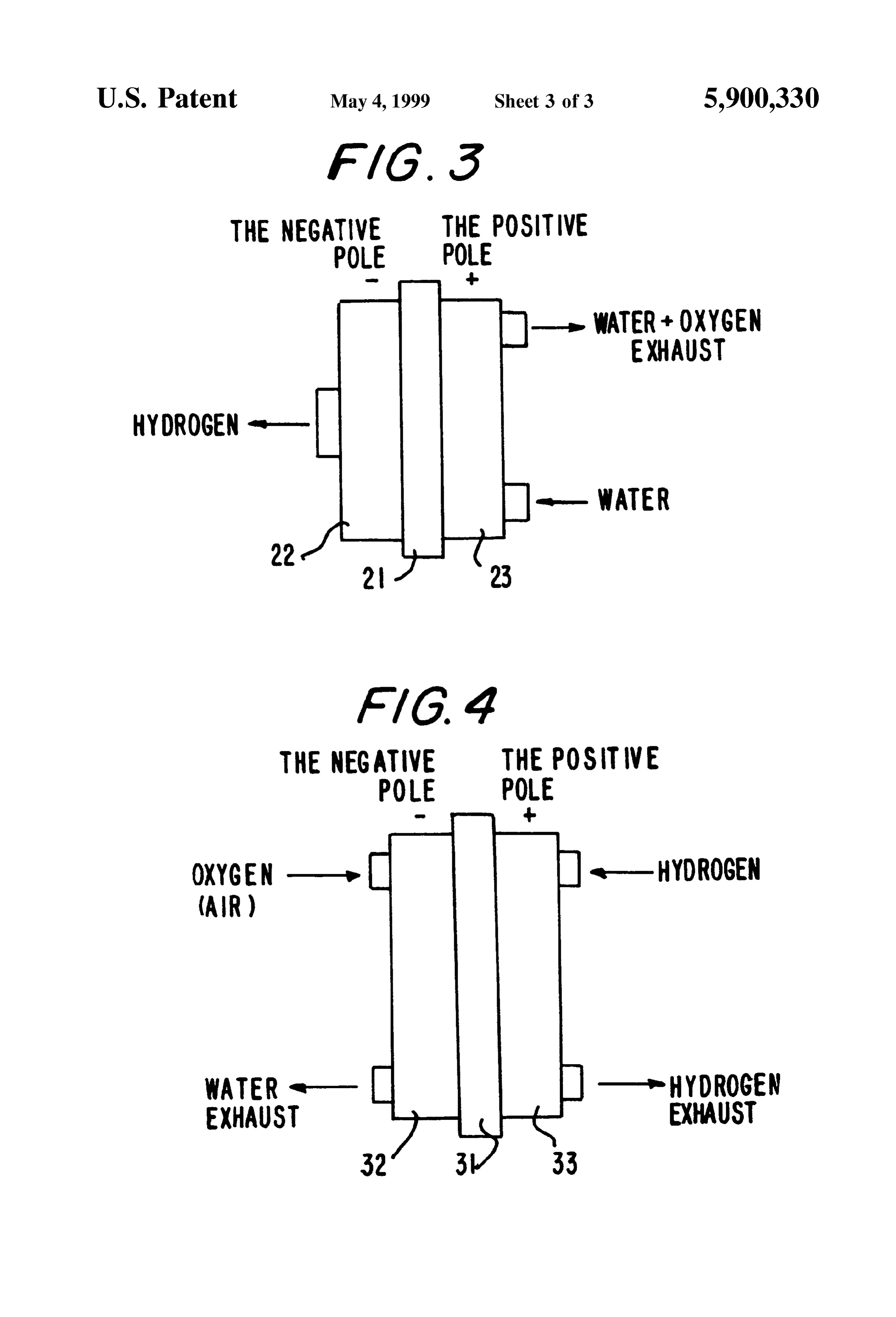
environmentally-Safe fuel for both heating and electric FIG. 3 shows the electrolysis-fuel cell of the present power generation, especially for automobiles. invention functioning as electrolysis, i.e., the producing of
Page 8
chemical changes by the passage of an electric current Sumption device, such as electrolysis-fuel cell 10 which through an electrolyte, a nonmetallic electric conductor in consumes the hydrogen released from the hydrogen Storage which current is carried by the movement of ions, or a tank 12 (using heat exchanger 5a) to provide electricity Substance that when dissolved in a Suitable solvent or when which powerS motor 18, which, for example, can propel a fused becomes an ionic conductor. car. The process of the present invention is described in FIG. 4 shows the electrolysis-fuel cell of the present further detail below.
invention functioning as a fuel cell which produces the Initially, water enters the electrolysis fuel cell 10, and in power to propel the automobile. conjunction with a Supplied Single electric charge, electri cally disintegrates the Supplied water to create hydrogen and
DETAILED DESCRIPTION OF THE OXygen.
PREFERRED EMBODIMENT The hydrogen, which is Stored in the hydrogen Storage The following presents a detailed description of a pre tank 12, and the oxygen, taken from air in the atmosphere, ferred embodiment of the present invention. AS discussed are supplied to the electrolysis-fuel cell 10 by compressor above, this invention relates generally to a power device for 14, In which work together to create the power of the device.
turn, this power propells motor 18 thereby generating use in hydrogen fuel cell cars. More Specifically, the present moving power.
invention discloses a novel power device which will not create any environmentally polluting exhaust (i.e., it does In Sum, the power device of the present invention pro not emit any carbon dioxide), and is extremely efficient, long vides power to practical applications, Such as electric cars, lasting, quiet and inexpensive to produce. Also, the device of by efficiently creating electrical power from hydrogen fuel the present invention does not require a large area and there and a Small, light electrolysis fuel cell. Additionally, the is no concern about explosion. Additionally, this power hydrogen Storage tank 12 is structured with hydrogen Stor device can replace the use of gas and electricity as the Source age alloys, Such as titanium-iron alloy or lanthanum-nickel of power in homes, factories, hotels, etc. alloy, but is not limited to these alloys. However, the alloys The method and device of the present invention creates ficient are limited to those with a high hydrogen adsorption coef hydrogen from Supplied water and electricity, and an 25 micro-pulverized at low temperatures and to those which are not electrolysis-electrical cell Section produces electric power by the hydrogen adsorption. This is impor from the Supplied hydrogen and air. The hydrogen is then tant So that the Storage of the hydrogen can last for an Stored in a Storage Section furnished for Such storage, while extended period of time, and So that the hydrogen Storage a power Section converts the electricity created in the above tank 12 does not have to be replaced often. mentioned electrolysis-electrical cell to power which pro Also, temperature control is crucial to the Storing of pells the car. hydrogen in the hydrogen Storage tank 12, the removal of The power device of the present invention has Several hydrogen from the hydrogen Storage tank 12, the electrical Special features which are vast improvements over the Solving at electrolysis-fuel cell 10 and the efficient creation existing designs. First, the electrical power is created by the of electric power. This temperature control of the hydrogen hydrogen Stored in the above mentioned Storage Section. 35 Storage tank 12 and electrolysis-fuel cell 10 is accomplished Second, the electrolysis instrument fuel cell is Structured with thermoelectrical heat pump 5b and heat exchanger 5a with three layers, a platinum electrode, a multiplex polymer in a cooling loop. Furthermore, the Storage rate can be raised membrane and an iridium electrode. Third, the Storage by cooling the hydrogen Storage alloy used when Sending Section of the power device of the present invention is made hydrogen
Since the to the hydrogen Storage tank 12. Additionally, hydrogen Storage alloy heats up when taking of a hydrogen Storage metal alloy. Fourth, the power Section contains a motor which is a Storage cell charged with the 40 hydrogen out of the hydrogen Storage tank 12, cooling is power created at a fixed rate in the electrolysis-electrical cell important at this Stage to maintain efficiency. and Supplies necessary power at the time of acceleration, and Next, controller 16 controls the turning Speed and torque a controller that controls a charge and discharge of the above of motor 18. Controller 16 contains a storage cell for mentioned Storage cell and controls the rotation Speed of the accelerating time. This Storage cell Supplements a part of the motor and its torque. 45 electric power that motor 18 needs at the time of acceleration With the above mentioned structures of storing hydrogen and charging at the time of fixed speed of the enforced created from Supplied water and electricity, the power device practice. Also, the power device of the present invention of the present invention can generate power from the elec exhausts oxygen resulting from the electrically resolved tricity created by the Stored hydrogen and the Supplied air. water at the time the hydrogen is Supplied. A Small amount For instance, with the above Structure, a dangerous hydrogen 50 of water results from the oxidation reaction at the time of the fuel tank exchange or refill of hydrogen would not be creation of the electric power. Heat is also generated from necessary, and with a one time charge, a hydrogen fuel cell motor 18. However, this exhaust and heat emission is very car that has enough driving distance can be offered. Small compared to a conventional car with an internal The following description of a preferred embodiment of combustion engine.
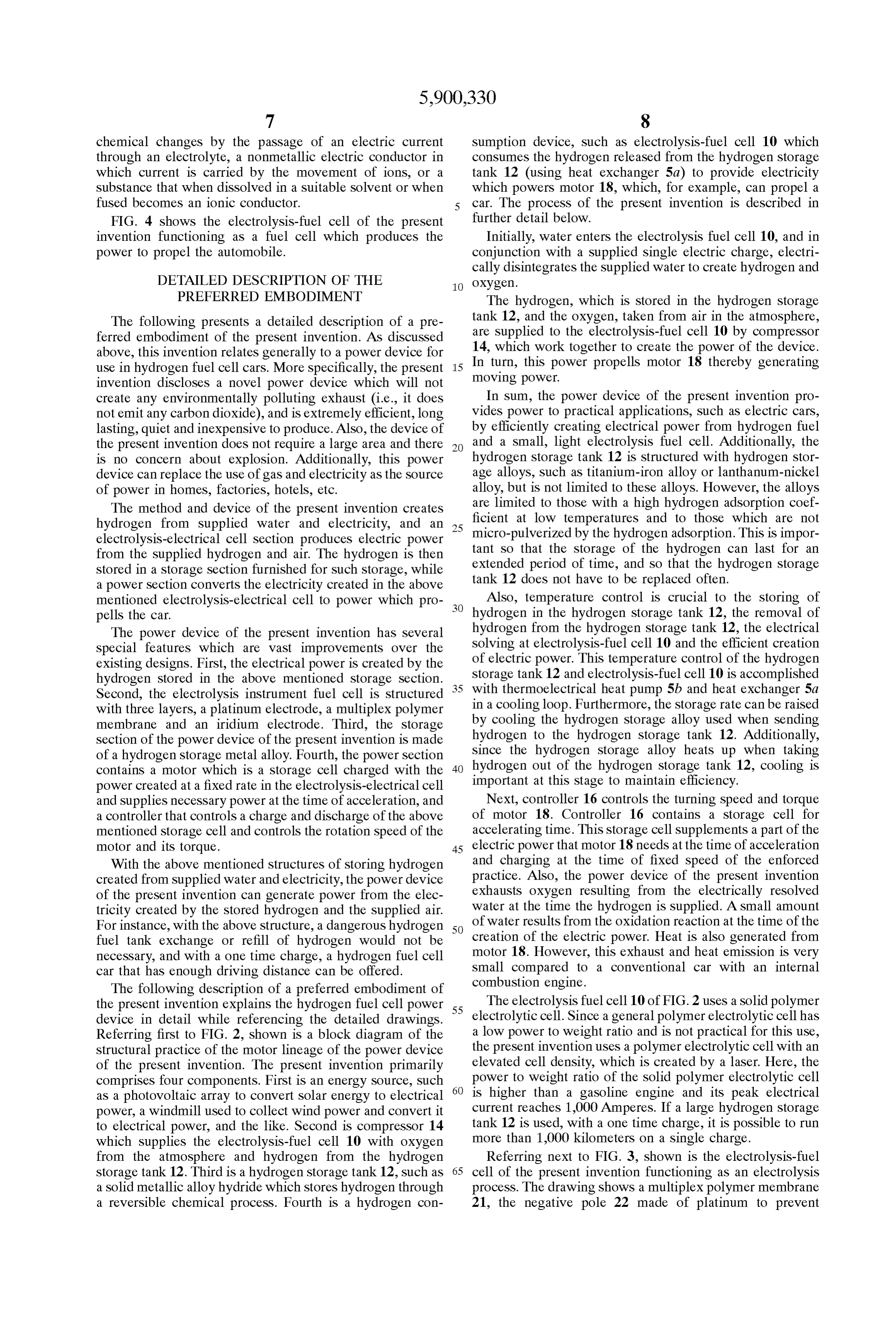
the present invention explains the hydrogen fuel cell power 55 The electrolysis fuel cell 10 of FIG. 2 uses a solid polymer device in detail while referencing the detailed drawings. electrolytic cell. Since a general polymer electrolytic cell has Referring first to FIG. 2, shown is a block diagram of the a low power to weight ratio and is not practical for this use, Structural practice of the motor lineage of the power device the present invention uses a polymer electrolytic cell with an of the present invention. The present invention primarily elevated cell density, which is created by a laser. Here, the comprises four components. First is an energy Source, Such 60 power to weight ratio of the Solid polymer electrolytic cell as a photovoltaic array to convert Solar energy to electrical is higher than a gasoline engine and its peak electrical power, a windmill used to collect wind power and convert it current reaches 1,000 Amperes. If a large hydrogen Storage to electrical power, and the like. Second is compressor 14 tank 12 is used, with a one time charge, it is possible to run which supplies the electrolysis-fuel cell 10 with oxygen more than 1,000 kilometers on a single charge. from the atmosphere and hydrogen from the hydrogen Referring next to FIG. 3, shown is the electrolysis-fuel Storage tank 12. Third is a hydrogen Storage tank 12, Such as 65 cell of the present invention functioning as an electrolysis a Solid metallic alloy hydride which Stores hydrogen through process. The drawing shows a multiplex polymer membrane a reversible chemical process. Fourth is a hydrogen con 21, the negative pole 22 made of platinum to prevent
Page 9
oxidation, and the positive pole 23 made of an iridium Also according to the present invention, the Storage of membrane to reduce loSS of oxygen by over Voltage, which hydrogen created from the Supplied water and electricity, execute the function of the electrolytic fluid. and the creation of electric power from this Stored hydrogen In this process, water is Supplied to the positive pole 23 and Supplied air, this power device generates electric power and electricity is Supplied to the region between the positive which can power a variety of different machines Such as pole 23 and negative pole 22. The electricity causes hydro automobiles, boats, etc., as well as entire homes, Stores, gen ions from the Supplied water to move toward the Schools, hotels, factories, etc. Therefore, with this invention, negative pole 22. This results in the creation of hydrogen at the dangerous exchange of hydrogen fuel tanks and hydro the negative pole 22 and oxygen at the positive pole 23. gen refills become unnecessary, and a hydrogen fuel cell car, Furthermore, any form of electricity, Such as that used for boat, etc., which has a large traveling distance with a one household purposes, will produce the desired results as time electrical charge can be offered.
previously mentioned. However, “midnight' electricity While the present invention has been described with reduces the cost of creating the hydrogen fuel in the proceSS reference to one or more preferred embodiments, Such of the present invention. Also, regarding the Supplied water, embodiments are merely exemplary and are not intended to any water Source will Suffice for the present invention to be limiting or represent an exhaustive enumeration of all aspects of the invention. The Scope of the invention, work, however water in which harmful ions have been 15 therefore, removed by an ion removing cartridge produces the best Further, it shall will be defined solely by the following claims.
be apparent to those of skill in the art that results.
numerous changes may be made in Such details without
Furthermore, the created hydrogen must be cooled before departing from the Spirit and the principles of the invention. being Stored for later use. This is accomplished at the heat What is claimed is:
eXchanger 5a, whereby the hydrogen is sent to the hydrogen 1. A power device for creating power from water and Storage tank 12 via compressor 14 after going through a electricity, Said power device comprising: water remover (not shown) and an oxygen remover (not an energy Source, shown). a hydrogen Storage device; Finally, referring to FIG. 4, shown is the electrolysis-fuel an electrolysis-fuel cell; and cell of the present invention functioning as a fuel cell. This 25 figure demonstrates that when oxygen is Supplied to the a compreSSOr, negative pole 32 and hydrogen is Supplied to the positive wherein Said electrolysis-fuel cell receives oxygen from pole 33, Oxidation occurs and electric power is generated by Said compressor, hydrogen from Said hydrogen Storage the electrode. The reaction is as follows: device, water from an external Source and an electric Positive charge from Said energy Source; wherein Said electrolysis-fuel cell electrically disintegrates Said
H, - 2H +2e. water into hydrogen and oxygen; wherein Said hydro gen is Stored in Said hydrogen Storage device and Said
Negative oxygen is purged from Said electrolysis-fuel cell as
exhaust, and wherein Said electrolysis-fuel cell com 2 2 2 bines Said hydrogen with air in Said electrolysis-fuel Overall Cell Reaction cell to produce electric power.
2. A power device according to claim 1, wherein Said 1 power device further comprises a heat eXchanger, wherein H, + so. - H.O Said heat eXchanger controls the temperature of Said hydro 40 gen Storage device and Said hydrogen consumption device.
3. A power device according to claim 2, wherein Said
According to the above described System of the present power device further comprises a controller, wherein Said invention, the creation of electricity is conducted through controller controls the power sent to the motor of the the formation of water, with electrons being created in the machine to be powered.
positive pole 33. Furthermore, the Voltage occurrence 45 4. A power device according to claim 1, wherein Said changes according to the current density of the electricity hydrogen Storage device is a metal alloy hydride Storage created, but ranges from about 0.75 V to about 1.0 V per cell. tank.
With the present invention, connecting Several hundred cells 5. A power device according to claim 1, wherein Said in Series creates the necessary Voltage for optimal efficiency energy Source is a photovoltaic array which converts Solar in the operation of the fuel cell. 50 energy to electrical power.
Additionally, referring back to FIG. 1, when creating 6. A power device according to claim 1 wherein Said electric power with the electrolysis fuel cell 10, it is impor electrolysis-fuel cell comprises a Solid polymer electrolyte tant to maintain energy efficiency by exhausting the heat that cell.
was created in the electrolysis fuel cell 10. This exhaustion 7. A method for generating power using an electrolysis occurs through the heat eXchanger 5a. AS explained in detail 55 fuel cell in which hydrogen is created from Water and an above, according to the present invention, because hydrogen electric charge, Said method comprising the following Steps: is created from the Supplied water and electricity in elec Supplying water and an electric charge to Said trolysis fuel cell 10, the dangerous hydrogen fuel tank electrolysis-fuel cell; eXchange or refill processes become obsolete. electrically disintegrating Said water into hydrogen and Also according to the present invention, by using a Small, OXygen, light weight, high power to weight ratio electrolysis fuel cell 60 Storing Said hydrogen in a hydrogen Storage device, and 10 for the source of moving power, a highly efficient electric combining Said hydrogen with air to generate Said power; charge and discharge can be obtained. Therefore, with one wherein a compressor Supplies Said electrolysis-fuel cell charge, Sufficient driving distance, in the range of 1000 kilometers can be obtained. Furthermore, applications of this with Said oxygen;
electrolytic fuel cell are not limited to cars but also can be 65 wherein Said compressor transferS Said hydrogen from applied to boats, trains and airplanes, or for cooling, heating Said hydrogen Storage device to Said electrolysis-fuel and home electrical power uses. cell;
Page 10
wherein a water Source Supplies said electrolysis-fuel cell wherein an electric charge from Said energy Source and with Said water; and water from Said water Source are provided to Said wherein an energy Source Supplies Said electrolysis-fuel electrolysis-fuel cell; wherein Said electrolysis-fuel cell cell with Said electric charge. electrically disintegrates Said water into hydrogen and 8. A method for generating power according to claim 7, Oxygen, thereby providing hydrogen to Said hydrogen wherein Said method further comprises the Step of: Storage device; and wherein hydrogen from Said hydro controlling the temperature of Said hydrogen Storage gen Storage device and oxygen from the atmosphere are provided to Said electrolysis-fuel cell through Said device and Said electrolysis-fuel cell. compressor, thereby creating electric power, water 9. A method for generating power according to claim 8, which is extracted as exhaust and hydrogen which is wherein Said controlling is performed by a heat eXchanger. provided to Said hydrogen Storage device. 10. A method for generating power according to claim 7, 15. A power device according to claim 14, wherein Said wherein Said method further comprises the Step of: power device further comprises a heat eXchanger, wherein controlling the power Sent to the motor of the machine Said heat eXchanger controls the temperature of Said hydro being powered. gen Storage device and Said electrolysis-fuel cell. 11. A method for generating power according to claim 10, 15 16. A power device according to claim 15, wherein Said wherein Said controlling is performed by a controller. power device further comprises a controller, wherein Said 12. A method for generating power according to claim 7, controller controls the power sent to the motor of the wherein Said hydrogen Storage device is a metal alloy machine to be powered.
hydride Storage tank. 17. A power device according to claim 14, wherein Said 13. A method for generating power according to claim 7, hydrogen Storage device is a metal alloy hydride Storage wherein Said energy Source is a photovoltaic array which tank.
converts Solar energy to electrical power. 18. A power device according to claim 14, wherein Said 14. A power device comprising: energy Source is a photovolatic array which converts Solar an energy Source, energy to electrical power.
a Water Source, 25 19. A power device according to claim 14 wherein said an electrolysis-fuel cell, electrolysis-fuel cell comprises a Solid polymer electrolyte cell.
a hydrogen Storage device; and a compreSSOr,
Page 11
UNITED STATES PATENT AND TRADEMARK OFFICE
CERTIFICATE OF CORRECTION
INVENTOR(S) : Kagitani
It is certified that error appears in the above-indentified patent and that said Letters Patent is hereby corrected as shown below:
Front Page, the Inventor's last name is incorrect. Please change "Kagatani" to --Kagita ni--. Signed and Sealed this
Nineteenth Day of October, 1999
Q. TOEDD DICKINSON
Attesting Officer Acting Commissioner of Patents and Trade marks

Page 12
UNITED STATES PATENT AND TRADEMARK OFFICE
CERTIFICATE OF CORRECTION
PATENT NO. : 5,900,330 Page 1 of 1
INVENTOR(S) : Kagitani
It is certified that error appears in the above-identified patent and that said Letters Patent is hereby corrected as shown below:
Title page, Item 54 and Column 1, line 1,
Please change the title from “POWER DEVICE to -- HYDROGEN,
OXYGEN GENERATOR AND POWER DEVICE --
Signed and Sealed this
Twenty-ninth Day of April, 2003
JAMES E ROGAN
Director of the United States Patent and Trademark Office

Provenance
- Collection
- Cited prior art
- Original PDF
- patentimages.storage.googleapis.com →
- Filed
- 1997-09-25
- Pages
- 12
- Method
- pdftotext (the PDF's own text layer) + pdftoppm 300dpi page scans
- Source
- Google Patents bibliographic record
- Granted
- 1999-05-04
- Inventors
- Takeo Kagatani
- Transcribed from
- patentimages.storage.googleapis.com →