patent · US5555872
Fuel pump control device for internal combustion engine
17 September 1996
Page 1 — bibliographic record
IIIHHHH
United States Patent (19) 11 Patent Number: 5,555,872 Takeuchi et al. 45) Date of Patent: Sep. 17, 1996
54 FUEL PUMP CONTROL DEVICE FOR 5,293,299 3/1994 Iwabuchi................................. 123/497 INTERNAL COMBUSTON ENGINE 5,313,923 5/1994 Takeuchi et al.. 5,379,741 1/1995 Matysiewicz ........................... 123A497 75) Inventors: Shigeru Takeuchi, Gamagouri;
Taketoshi Sato, Kariya, Takahiko FOREIGN PATENT DOCUMENTS
Hasegawa, Nukata-gun, all of Japan 60-261969 12/1985 Japan.
73 Assignee: Nippondenso Co., Ltd., Kariya, Japan 62-131965 6/1987 Japan.
(21) Appl. No.: 449,359 Primary Examiner-Carl S. Miller 22 Filed: May 24, 1995 Attorney, Agent, or Firm-Cushman, Darby & Cushman (30) Foreign Application Priority Data 57) ABSTRACT May 26, 1994 JP Japan .................................... 6-112875. In a pump control circuit, if a battery voltage declines to a 5 voltage level lower than that required to insure a constant 51) Int. Cl. ..................................................... F02M 37/04 voltage, a low-voltage detection circuit outputs a low volt 52 U.S. Cl. ...................... 123/497; 123/198 D age detection signal. In the case of the decline in the battery 58 Field of Search ..................................... 123/497, 357, voltage, an NOR circuit outputs the conversion signal from 123/358, 359, 198 D, 379 an internal logic section, and a pump control signal bypass ing the internal logic section, giving priority to the latter 56) References Cited signal. A motor drive circuit turns FET ON and OFF in
According to ON/OFF of the FET, the intermittent control of 4,359,984 11/1982 Nakao ..................................... 123f497 the current from the battery to the pump drive motor is 4,430,980 2/1984 Pidgeon .................................. 123,497 performed.
4,791,905 12/1988 Furuta ..................................... 123,497 4,919,102 4/1990 Iwabuchi a - a a 123,497 5,092.302 3/1992 Mohan .................................... 123f497 12 Claims, 5 Drawing Sheets
Page 2
Drawing sheet — no readable text.
Page 3
Drawing sheet — no readable text.
Page 4
Drawing sheet — no readable text.
Page 5
Drawing sheet — no readable text.
Page 6
Drawing sheet — no readable text.
Page 7
FUEL PUMP CONTROL DEVICE FOR internal logic section 34 becomes unstable so that the pump INTERNAL COMBUSTION ENGINE drive motor 32 stops unexpectedly, thus causing impedi ments to starting the engine.
CROSS REFERENCE TO RELATED Furthermore, due to a variety of engine control methods APPLICATION and engine specifications, a further increase in the input modes of the internal logic section 34 and more complex
This application is based upon and claims priority of internal circuits can be expected. For this reason, it becomes Japanese Patent Application No. 6-112875 filed on May 26, difficult to insure stable operation of the internal logic 1994, the content of which is incorporated herein by refer section 34 during the decline in battery voltage. C. 10
SUMMARY OF THE INVENTION
BACKGROUND OF THE INVENTION
1. Field of the Invention This invention has been made to solve the above problems and its purpose is to provide a control device for a fuel pump
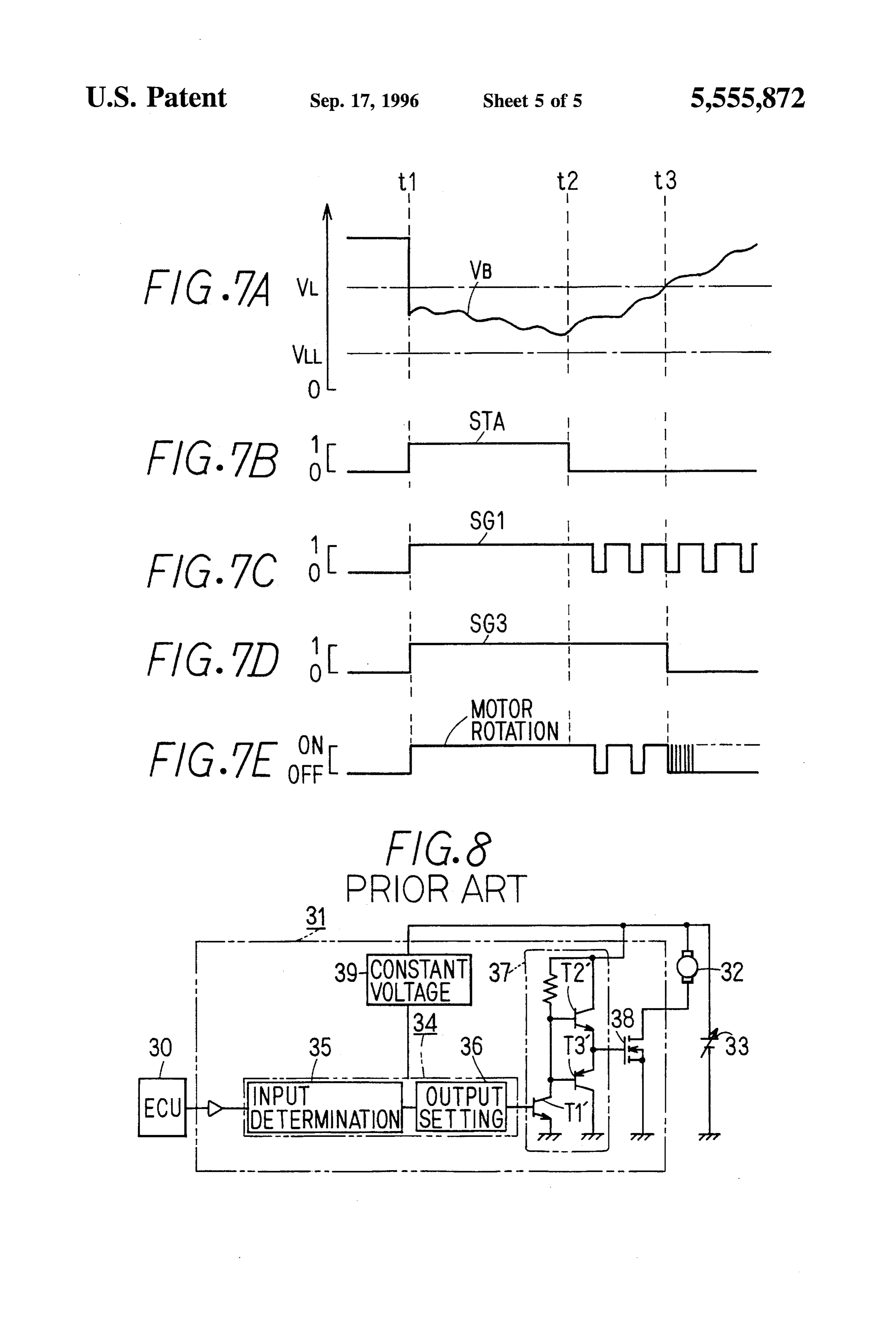
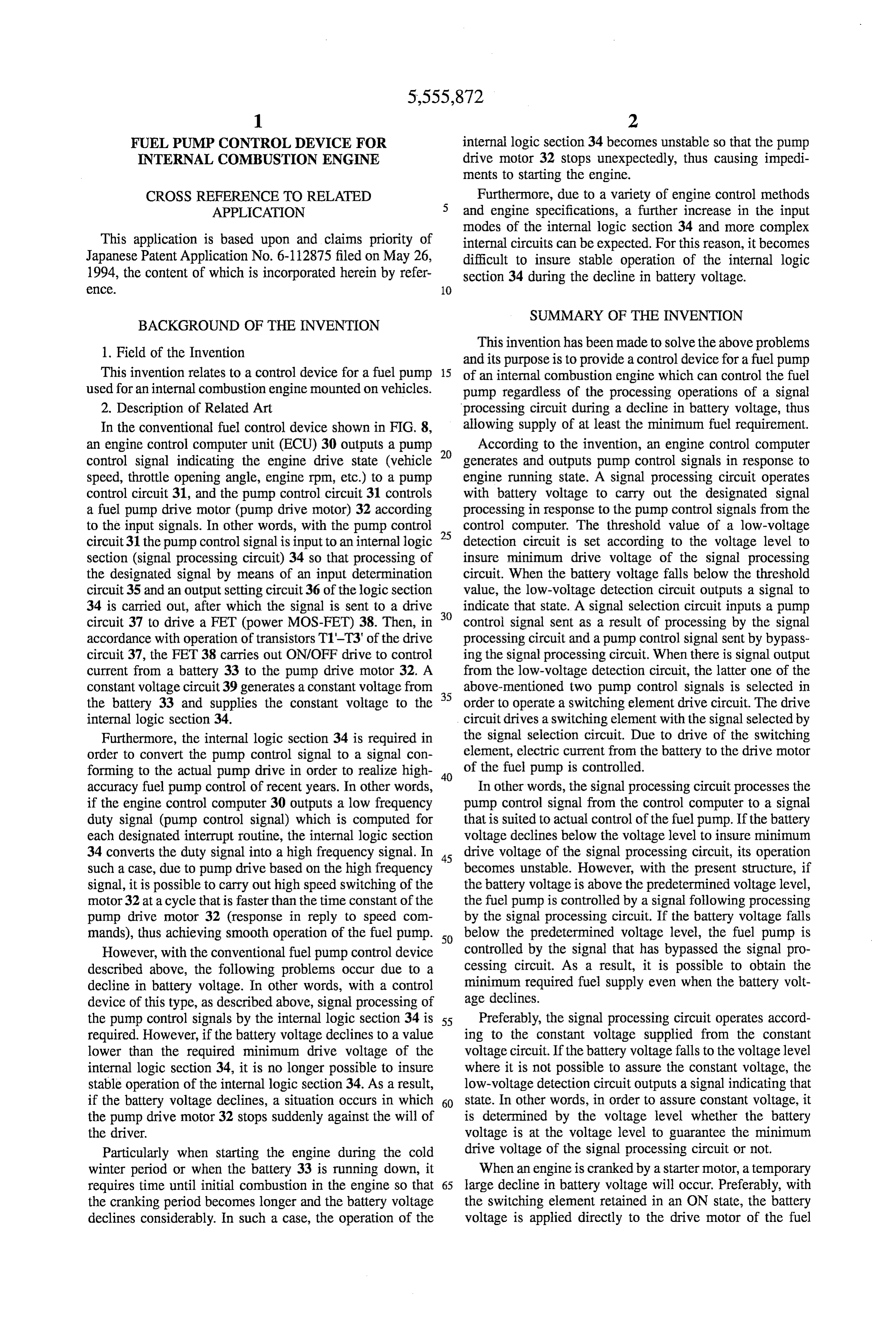
This invention relates to a control device for a fuel pump 15 of an internal combustion engine which can control the fuel used for an internal combustion engine mounted on vehicles. pump regardless of the processing operations of a signal 2. Description of Related Art processing circuit during a decline in battery voltage, thus In the conventional fuel control device shown in FIG. 8, allowing supply of at least the minimum fuel requirement. an engine control computer unit (ECU) 30 outputs a pump 20 According to the invention, an engine control computer control signal indicating the engine drive state (vehicle generates and outputs pump control signals in response to speed, throttle opening angle, engine rpm, etc.) to a pump engine running state. A signal processing circuit operates control circuit 31, and the pump control circuit 31 controls with battery voltage to carry out the designated signal a fuel pump drive motor (pump drive motor) 32 according processing in response to the pump control signals from the to the input signals. In other words, with the pump control 25 control computer. The threshold value of a low-voltage circuit 31 the pump control signal is input to an internal logic detection circuit is set according to the voltage level to section (signal processing circuit) 34 so that processing of insure minimum drive voltage of the signal processing the designated signal by means of an input determination circuit. When the battery voltage falls below the threshold circuit 35 and an output setting circuit 36 of the logic section value, the low-voltage detection circuit outputs a signal to 34 is carried out, after which the signal is sent to a drive 30 indicate that state. A signal selection circuit inputs a pump circuit 37 to drive a FET (power MOS-FET) 38. Then, in control signal sent as a result of processing by the signal accordance with operation of transistors T1'-T3' of the drive processing circuit and a pump control signal sent by bypass circuit 37, the FET 38 carries out ON/OFF drive to control ing the signal processing circuit. When there is signal output current from a battery 33 to the pump drive motor 32. A from the low-voltage detection circuit, the latter one of the constant voltage circuit 39 generates a constant voltage from 35 above-mentioned two pump control signals is selected in the battery 33 and supplies the constant voltage to the order to operate a switching element drive circuit. The drive internal logic section 34. circuit drives a switching element with the signal selected by Furthermore, the internal logic section 34 is required in the signal selection circuit. Due to drive of the switching order to convert the pump control signal to a signal con element, electric current from the battery to the drive motor forming to the actual pump drive in order to realize high 40 of the fuel pump is controlled.
accuracy fuel pump control of recent years. In other words, In other words, the signal processing circuit processes the if the engine control computer 30 outputs a low frequency pump control signal from the control computer to a signal duty signal (pump control signal) which is computed for that is suited to actual control of the fuel pump. If the battery each designated interrupt routine, the internal logic section voltage declines below the voltage level to insure minimum 34 converts the duty signal into a high frequency signal. In 45 drive voltage of the signal processing circuit, its operation such a case, due to pump drive based on the high frequency becomes unstable. However, with the present structure, if signal, it is possible to carry out high speed switching of the the battery voltage is above the predetermined voltage level, motor 32 at a cycle that is faster than the time constant of the the fuel pump is controlled by a signal following processing pump drive motor 32 (response in reply to speed com by the signal processing circuit. If the battery voltage falls mands), thus achieving smooth operation of the fuel pump. 50 below the predetermined voltage level, the fuel pump is However, with the conventional fuel pump control device controlled by the signal that has bypassed the signal pro described above, the following problems occur due to a cessing circuit. As a result, it is possible to obtain the decline in battery voltage. In other words, with a control minimum required fuel supply even when the battery volt device of this type, as described above, signal processing of age declines.
the pump control signals by the internal logic section 34 is 55 Preferably, the signal processing circuit operates accord required. However, if the battery voltage declines to a value ing to the constant voltage supplied from the constant lower than the required minimum drive voltage of the voltage circuit. If the battery voltage falls to the voltage level internal logic section 34, it is no longer possible to insure where it is not possible to assure the constant voltage, the stable operation of the internal logic section 34. As a result, low-voltage detection circuit outputs a signal indicating that if the battery voltage declines, a situation occurs in which 60 state. In other words, in order to assure constant voltage, it the pump drive motor 32 stops suddenly against the will of is determined by the voltage level whether the battery the driver. voltage is at the voltage level to guarantee the minimum Particularly when starting the engine during the cold drive voltage of the signal processing circuit or not. winter period or when the battery 33 is running down, it When an engine is cranked by a starter motor, a temporary requires time until initial combustion in the engine so that 65 large decline in battery voltage will occur. Preferably, with the cranking period becomes longer and the battery voltage the switching element retained in an ON state, the battery declines considerably. In such a case, the operation of the voltage is applied directly to the drive motor of the fuel
Page 8
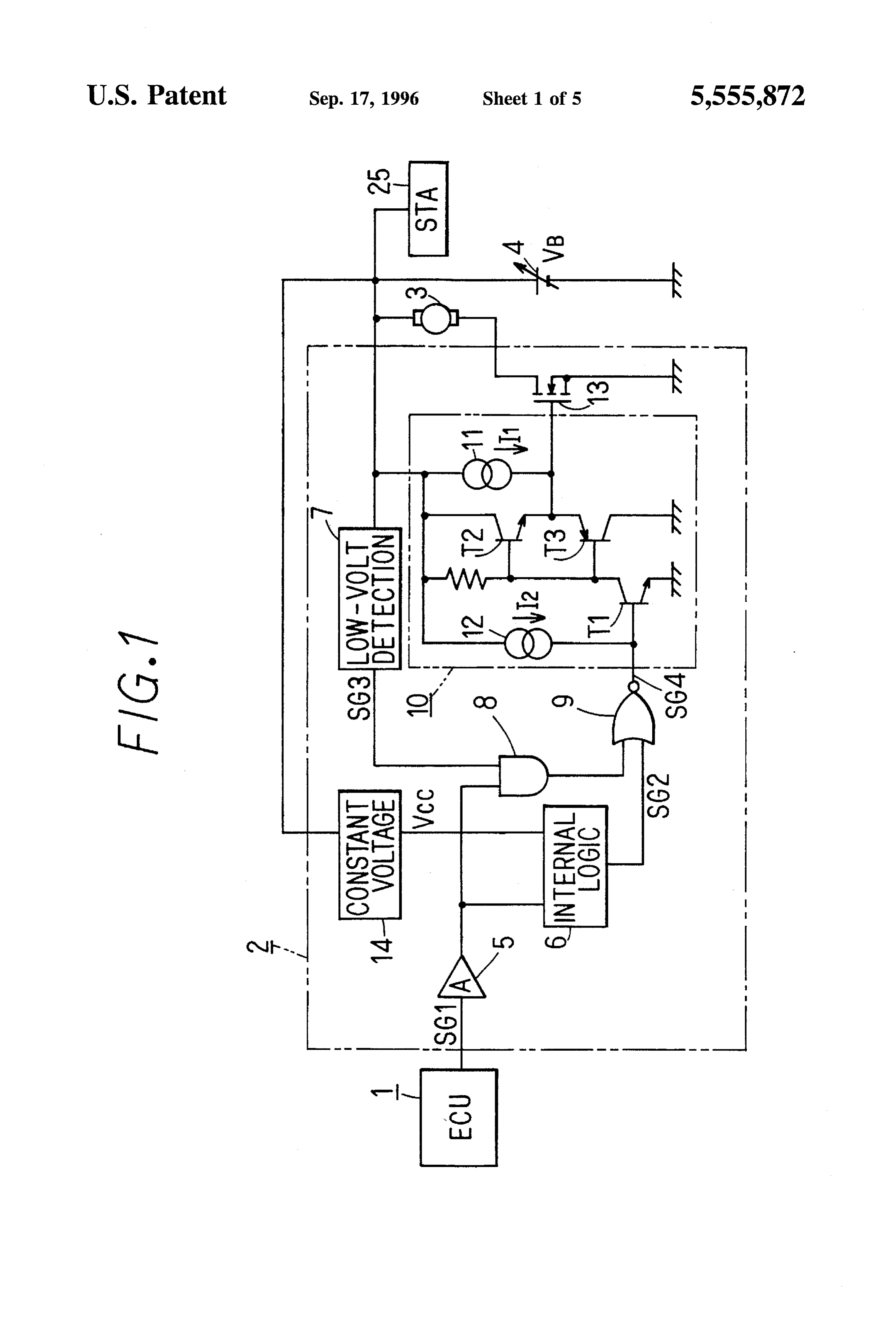
pump. In such a case, even if, for example, there is a decline to connect this to the ground side and thus create a so-called in battery voltage because the cranking period becomes high-side switching circuit. Also connected to the battery 4 longer, there is still fuel supply by the fuel pump and engine is a starter motor (STA) 25 in order to provide initial rotation starting is carried out. of the engine not shown in the figure. Preferably, if the battery voltage declines to a voltage 5 As shown in FIG. 2 illustrating the computer 1, there is level where it is no longer possible to guarantee operation of input to a CPU 1a of the various detection signals indicative the system for input of the pump control signal, the switch of the engine running state (vehicle speed signal SPD, ing element is turned OFF. In such a case, the pump which throttle opening angle signal TA, water temperature signal has declined to a state where control is not possible defi THW, ignition switch signal IG, etc.). The CPU 1a computes nitely stops, 10 the pump control amount for each designated interrupt based More preferably, if the battery voltage is at a voltage level on the above-mentioned detection signals, and then gener ates the required duty ratio signal in accordance with the between the threshold value of the low-voltage detection computation results. Further, the CPU la generates four circuit and the above-mentioned drive stop voltage, a drive modes of signals of differing duty ratio as shown in FIGS. power source section supplies the drive power to the switch 15 3A-3D: “H” mode signal, “M” mode signal, "L' mode ing element. A drive stop section turns the switching element signal, 'OFF' mode signal. In a single cycle (12 ms) of the OFF at the same voltage level to stop drive of the fuel pump. signal for each mode, the signal is divided into sections #1 Thus, even in cases where operation of the drive system to #3 at every 4 ms and set so that the signal level in each driving the switching element would become unstable due to section is different. Furthermore, in the description of this the decline in battery voltage, operation of the drive power 20 embodiment, the logic high level (5 V potential) is denoted source section and the drive stop section controls drive and as “1” and the logic low level (0 V potential) is denoted as stopping of the fuel pump. “0”.
The duty ratio signals generated by the CPU 1a pass
BRIEF DESCRIPTION OF THE DRAWINGS through OR circuit 1b, AND circuit 1c and OR circuit 1d, In the accompanying drawings: 25 and are then output to the pump control circuit 2 as pump control signals SG1. In the case of an abnormality in the
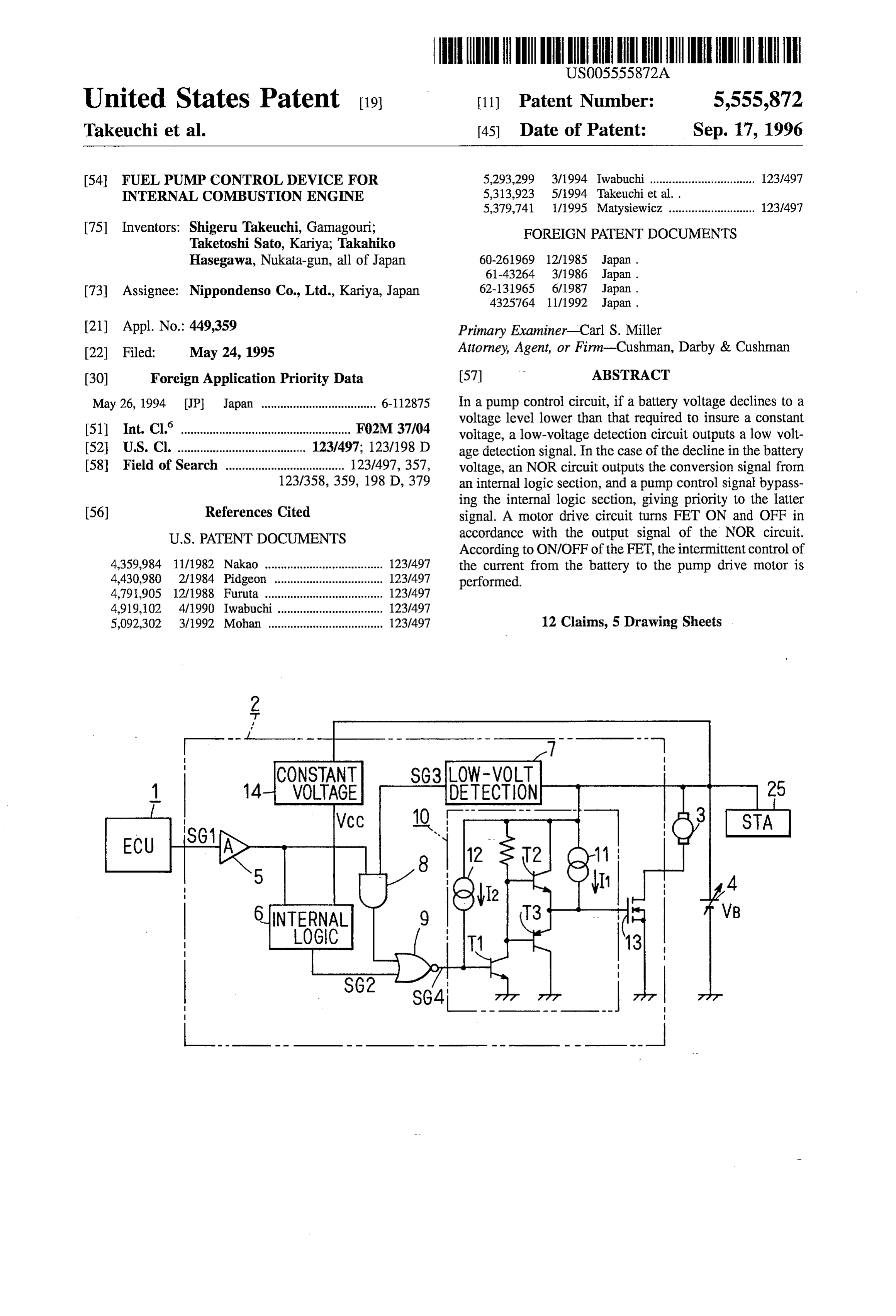
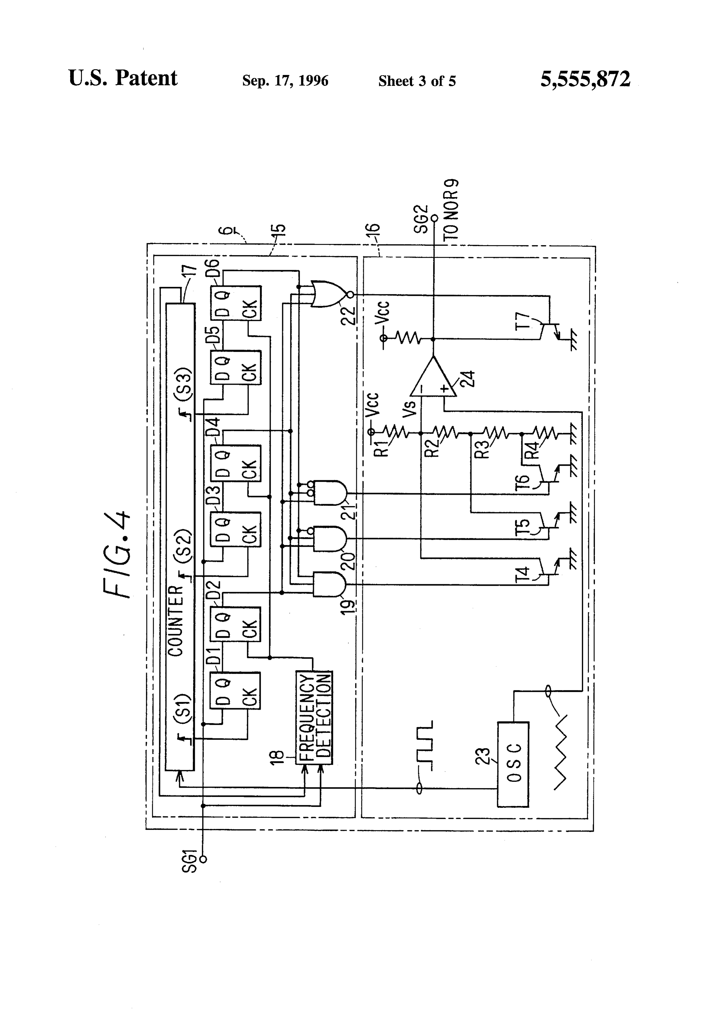
FIG. 1 is a circuit diagram showing an electrical circuit CPU 1a, “1” level is input to the OR circuit 1b. When the configuration of a fuel pump control device according to the engine rotational velocity is 0 rpm or greater, '1' level is embodiment of the invention; input to the AND circuit 1c. When the starter motor 25 is ON FIG. 2 is a circuit diagram showing the internal structure (during cranking), "1" level is input to the OR circuit 1d. of an engine control computer; 30 In the pump control circuit 2 shown in FIG. 1, the pump FIGS. 3A through 3D are waveform charts showing the control signal SG1 from the above-mentioned engine control 4-mode duty ratio signals generated by a CPU; computer 1 passes through an amplifier 5 and is input to the internal logic section 6 acting as the signal processing circuit
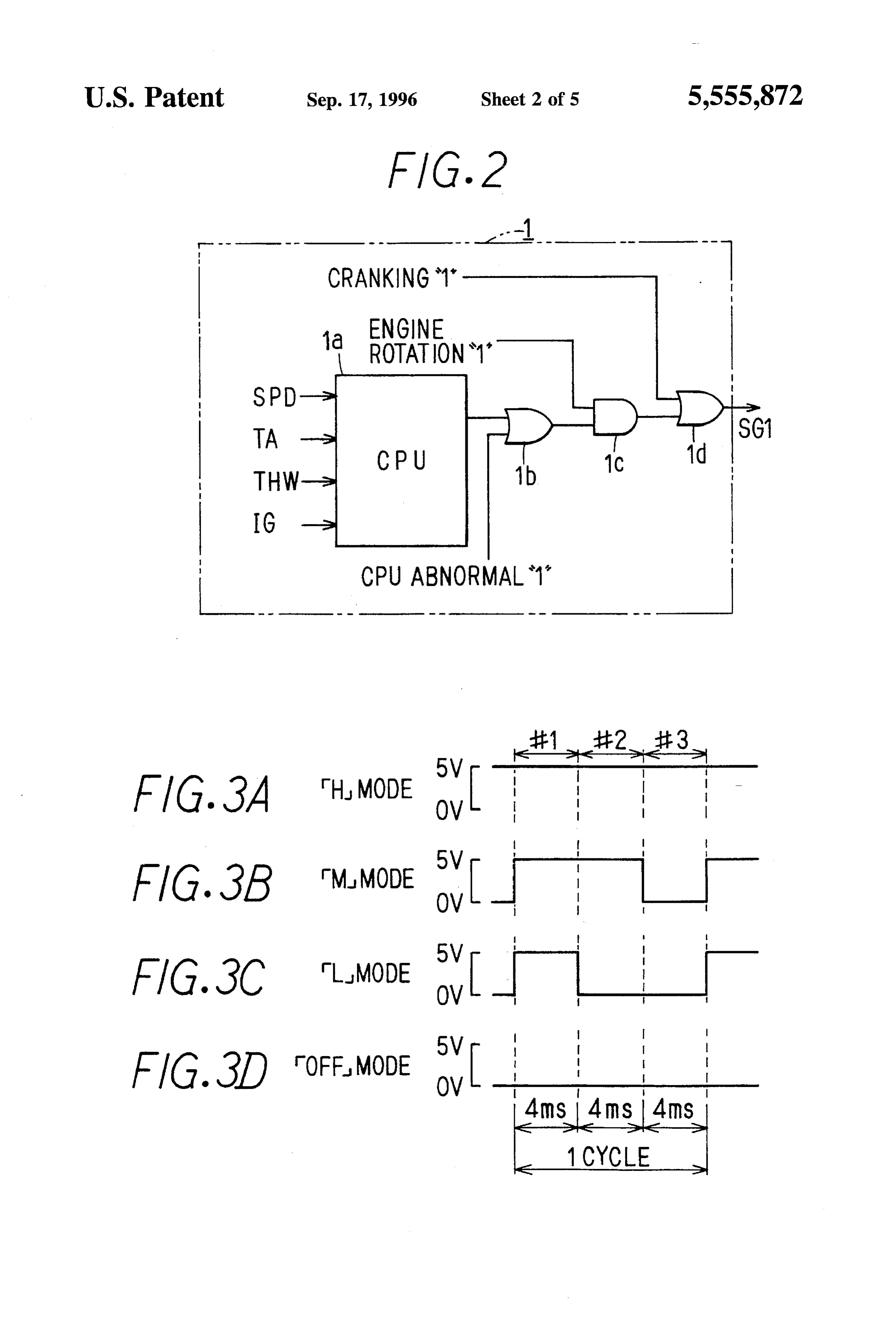
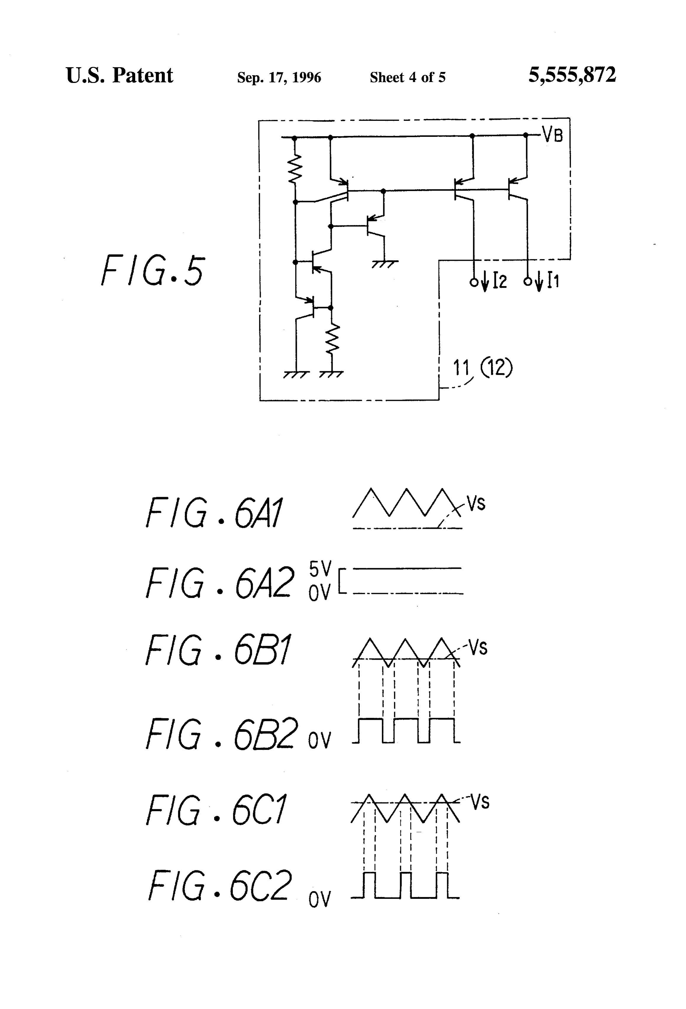
FIG. 4 is a circuitry diagram showing the structure of an and to an AND circuit 8. The internal logic section 6 is internal logic section; 35 driven according to the constant voltage Vcc (5 V) supplied FIG. 5 is a circuitry diagram showing the structure of a by the constant voltage circuit 14. The constant voltage constant current circuit; circuit 14 generates the constant voltage Vcc from the FIGS. 6A1 through 6C2 are waveform charts showing battery voltage VB. The internal logic section 6, in order to input and output of a comparator of an output setting circuit carry out high speed switching operation of the pump drive of the internal logic section; 40 motor 3, converts the pump control signal SG1 in low frequency duty to a high frequency duty signal and outputs
FIGS. 7A through 7E are waveform charts showing the converted signal SG2 to an NOR circuit 9. operation of a fuel pump control device in the embodiment; A low-voltage detection circuit 7 is connected to the and battery 4 and detects when the battery voltage VB declines
FIG. 8 is a circuitry diagram showing the electrical below a predetermined voltage level. In other words, the structure of a conventional fuel pump control device. 45 low-voltage detection circuit 7 compares the battery voltage DETAILED DESCRIPTION OF THE VB and a threshold value VL so that, when the battery PREFERRED EMBODIMENTS voltage VB declines (so that VBCVL), it outputs a low voltage detection signal SG3 ('1') indicating that state to the
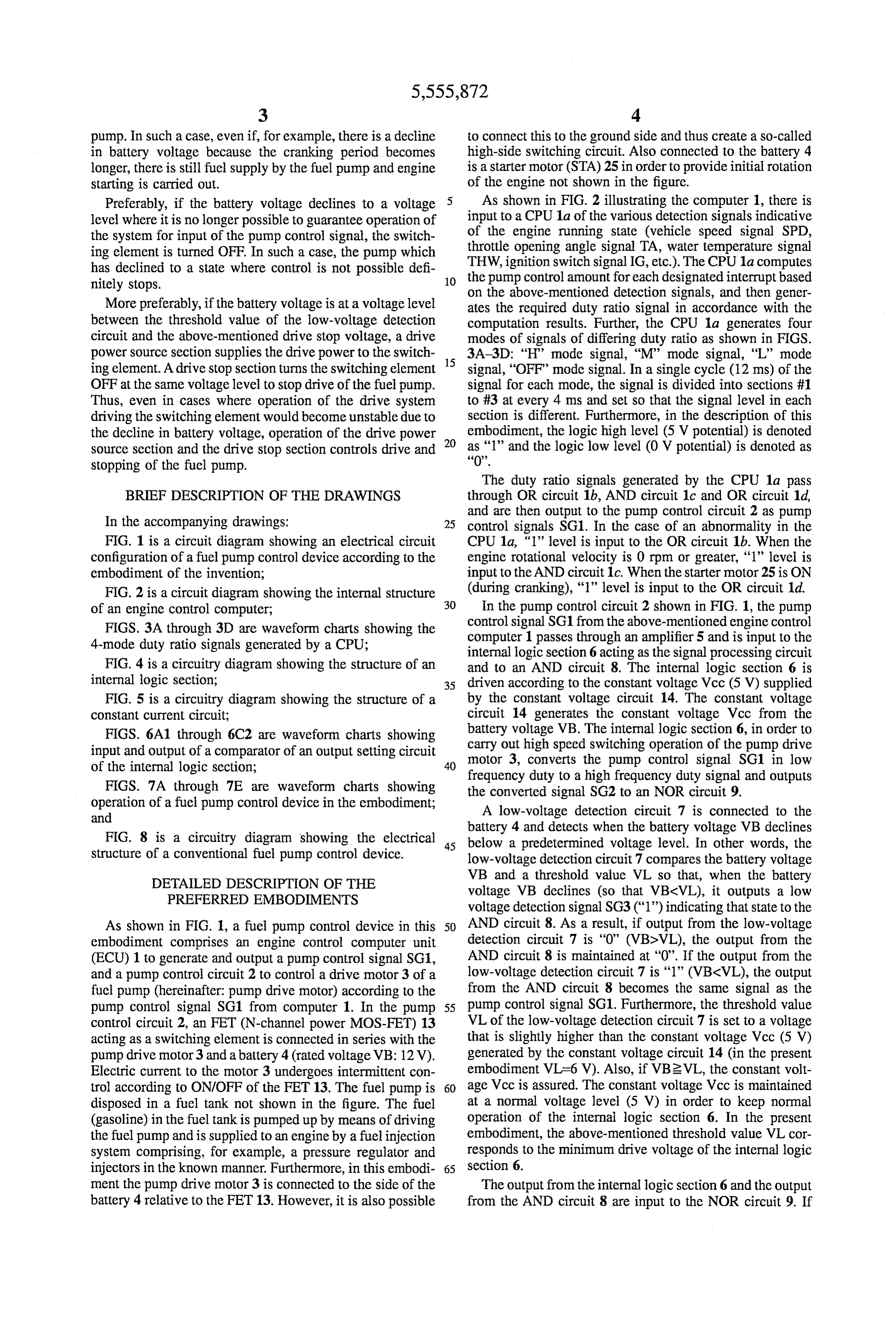
As shown in FIG. 1, a fuel pump control device in this 50 AND circuit 8. As a result, if output from the low-voltage embodiment comprises an engine control computer unit detection circuit 7 is "O" (VB>VL), the output from the (ECU) 1 to generate and output a pump control signal SG1, AND circuit 8 is maintained at "0". If the output from the and a pump control circuit 2 to control a drive motor 3 of a low-voltage detection circuit 7 is “1” (VBCVL), the output fuel pump (hereinafter: pump drive motor) according to the from the AND circuit 8 becomes the same signal as the pump control signal SG1 from computer 1. In the pump 55 pump control signal SG1. Furthermore, the threshold value control circuit 2, an FET (N-channel power MOS-FET) 13 VL of the low-voltage detection circuit 7 is set to a voltage acting as a switching element is connected in series with the that is slightly higher than the constant voltage Vcc (5 V) pump drive motor 3 and a battery 4 (rated voltage VB: 12V). generated by the constant voltage circuit 14 (in the present Electric current to the motor 3 undergoes intermittent con embodiment VL=6 V). Also, if VB2VL, the constant volt trol according to ON/OFF of the FET 13. The fuel pump is 60 age Vcc is assured. The constant voltage Vcc is maintained disposed in a fuel tank not shown in the figure. The fuel at a normal voltage level (5 V) in order to keep normal (gasoline) in the fuel tank is pumped up by means of driving operation of the internal logic section 6. In the present the fuel pump and is supplied to an engine by a fuel injection embodiment, the above-mentioned threshold value VL Cor System comprising, for example, a pressure regulator and responds to the minimum drive voltage of the internal logic injectors in the known manner. Furthermore, in this embodi- 65 section 6.
ment the pump drive motor 3 is connected to the side of the The output from the internal logic section 6 and the output battery 4 relative to the FET 13. However, it is also possible from the AND circuit 8 are input to the NOR circuit 9. If
Page 9
S 6 either of the input signals is “1”, the NOR circuit 9 causes voltage (1.5V-2.0 V) so that the FET 13 goes OFF and there the output signal SG4 to become "0". If both input signals is a danger of the pump drive motor 3 stopping unexpect are “0”, it causes the output signal SG4 to become “1”. In the edly. However, with the present structure, by supplying the present embodiment, a signal selection circuit is composed constant current I1 to the gate of the FET 13, it is possible of the AND circuit 8 and the NOR circuit 9. to turn ON the FET 13 even with the above-mentioned As a result, if the battery voltage VB is higher than the voltage decline and thus continue operation of the pump threshold value VL (VB2VL), the output from the AND drive motor 3.
circuit 8 is maintained at "0". The NOR circuit 9 outputs an When the battery voltage VB declines to a voltage level inversion signal SG4 of the converted signal SG2 from the (drive stop voltage) where it is no longer possible to guar internal logic section 6. If the battery voltage VB declines 10 antee operation of the input system in the stage prior to the below the threshold value VL (VBCVL), the AND circuit 8 transistor T1, the transistor T1 is maintained in an ON state outputs the pump control signal SG1 as it is and the NOR due to the constant current I2. In such a case, the transistor circuit 9 outputs the inversion signal of the pump control signal SG1. In other words, with the decline in the battery T3 goes ON so that the constant current I1 is pulled to the voltage VB, the NOR circuit 9 outputs the conversion signal 15 ground side and the FET 13 turns OFF. In other words, the SG2 from the internal logic section 6 and the pump control pump drive motor 3 maintains a stop state and the motor 3 signal SG1 that bypasses the internal logic section 6, giving is prevented from rotating on its own in a voltage range priority to the latter. Also, the system is constructed in such where control is difficult. If the battery voltage VB declines a way that the low-voltage detection circuit 7, the AND to a voltage VLL(=2 V in the embodiment) where operation circuit 8 and the NOR circuit 9 operate normally to produce 20 of the constant current circuits 11 and 12 is stopped, supply the output signal SG4 even if VBCVL. of constant current I1 and I2 is stopped. There is input of the output signal SG4 from the NOR Furthermore, regarding the setting values of the constant circuit 9 to the drive circuit (element drive circuit) driving current I1 and I2, it is preferable to set to values which are the FET 13. The drive circuit 10 turns the FET 13 ON and about 2 decimal places smaller than the current ability of the OFF according to the output signal SG4. More specifically, 25 transistor T2 so that there is no high speed switching of the in the drive circuit 10, the bases of transistors T2 and T3 FET13 when the battery voltage VB declines, and also that acting as complementary emitter follower circuits are con the constant current I1 via transistor T3 is pulled to the nected to the collector of the transistor T1 which undergoes ground side when the FET 13 is OFF (For example, about emitter grounding. In other words, when the transistor T1 is several 100 IA).
ON, the transistor T3 goes ON so that the gate of FET 13 is 30 The internal logic section 6 includes as shown in FIG. 4, pulled in the ground potential side and FET 13 turns OFF. At an input determination circuit 15 to determine the pump this time, supply of power from the battery 4 to the pump control signal SG1 from the engine control computer 1, and drive motor 3 is cut off. Conversely, if transistor T1 is OFF, an output setting circuit 16 to convert the pump control the transistor T2 goes ON so that voltage is supplied to the signal SG1 based on the determination results of the input gate of FET 13 and FET 13 turns ON. At this time, there is 35 determination circuit 15 to a high frequency signal for supply of electric power from the battery 4 to the pump drive output. The input determination circuit 15 comprises a motor 3. counter 17, a frequency detection circuit 18, the flip-flop Also, in the above-mentioned drive circuit 10, due to circuits D1-D6 and four logic circuits (AND circuits 19-21, supply of battery voltage VB between the collector and NOR circuit 22). The frequency detection circuit 18 gener emitter of the transistor T2, there is connection of a constant 40 ates a 1-pulse signal for each cycle of the pump control current circuit 11 generating a constant current I1. Due to signal SG1 (every 12 ms in the present embodiment) and the supply of the same battery voltage VB to the base of the signal is output to the flip-flop circuits D2, D4 and D6 as transistorT1, there is connection of a constant current circuit clock signals.
12 generating a constant current I2. The constant currents I1 The counter 17 computes the time based on the high and I2 are both supplied to the drive circuit 10 by means of 45 frequency pulse signals from an oscillator circuit 23 (e.g., 20 the same constant current source and are the same value kHz) and then detects the logic level from section #1 to (I1=I2). For example, the constant current circuits 11 and 12 section #3 of the pump control signal SG1. The clock signal are composed as shown in FIG. 5 so that, when VB22V, the is output to the flip-flop D1 during the detection time of the supply of the constant currents I1 and I2 are supplied, and 1st section of the same signal, the clock signal is output to when VBC2V, supply of the constant currents I1 and I2 is 50 flip-flop D2 during the detection time of the 2nd section, and stopped. It is also possible to provide a system where the the clock signal is output to the flip-flop D5 during the constant current circuits 11 and 12 are composed of different detection time of the 3rd section. At this time, the flip-flop constant current sources or a system where I1 does not equal D1 reads the logic level of the 1st section of the pump I2. However, by providing the systems described above control signal SG1, the flip-flop D3 reads the logic level of (FIG. 5), there is the advantage that is easier to match 55 the second section, and the flip-flop D5 reads the logic level characteristics. In the present embodiment, the drive power of the 3rd section. The flip-flops D2, D4 and D6 operate source section is composed of the constant current circuit 11, according to clock signals from the frequency detection and the drive stop section is composed of constant current circuit 18. At this timing, flip-flop D2 outputs the output circuit 12. signal of flip-flop D1, flip-flop D4 outputs the output signal Along with the decline in the battery voltage VB, the 60 of flip-flop D3, and flip-flop D6 outputs the output signal of constant current circuits 11 and 12 operate as follows. When flip-flop D5.
the base drive current of the transistor T2 declines as a result Based on the output signals from flip-flops D2, D4 and of a decline in the battery voltage VB, the collector satura D6, one of the outputs from the AND circuits 19–21 and the tion voltage of the transistor T2 becomes larger. At this time, NOR circuit 22 becomes “1” and is output to the output due to the decline in the maximum voltage between the 65 setting circuit 16 as the determination results of the pump collector and emitter of the transistor T2, the gate voltage of control signal SG1. If the pump control signal SG1 at this the FET 13 becomes lower than the FET drive minimum time is an "H" (high rotation speed) mode signal, the output
Page 10
of the AND circuit 19 becomes "1"; if the pump control goes to 'O'. Thus, the pump control signal SG1 is converged signal SG1 is an “M” (medium rotation speed) mode signal, to the required duty ratio signal corresponding to the engine the output of the AND circuit 20 becomes "1'; if the pump running conditions. At this time, because VBCVL as was the control signal SG1 is an "L' (low rotation speed) mode case during the times t1-t2 described above, the pump signal, the output of the AND circuit 21 becomes "1"; if the control signal SG1 bypasses the internal logic section 6 and pump control signal SG1 is an "OFF" (rotation stop) mode is input to the drive circuit 10, so that the FET 13 goes ON signal, the output of the NOR circuit 22 becomes "1". and OFF according to the input signals. In this case, the In the output setting circuit 16, the oscillator circuit 23 is pump drive motor 3 undergoes low-speed switching in the connected to the positive input terminal of a comparator 24. low frequency duty signal (pump control signal SG) so that Connected to a negative input terminal is a potential division O drive and stop are repeated and the fuel supplied to the fuel point of the constant voltage Vcc according to resistances injection system during engine starting is retained. R1-R4. The comparator 24 outputs the results of comparing When the engine starts successfully after time t2, the the high-frequency (20 kHz) triangular wave signals from battery 4 is charged subsequently by generation of an the oscillator circuit 23 and the standard voltage V's set by the constant voltage Vcc and the resistances R1-R4. Located 15 alternator so that the battery voltage VB gradually rises. At on the output Side of the comparator 24 is a transistor T7 time t3 where VB2VL, the low-voltage detection signal which fixes the conversion signal SG2 from the internal SG3 from the low-voltage detection circuit 7 returns to "0" logical section 6 to "0" level if the output of the NOR circuit level and the output from the AND circuit 8 becomes "O" 22 is “1”. level. In this case, the conversion signal SG2 in high The standard voltage Vs of the comparator 24 is set to one frequency from the internal logic section 6 is output from the of the three different voltage level values depending on the NOR circuit 9 so that the FET 13 undergoes high speed ON/OFF operation of the transistors T4-T6 according to the switching drive. In other words, after time t3 the pump drive outputs of the above-mentioned AND circuits 19–21. When motor 3 carries out the normal high speed switching drive. the output of the AND circuit 19 is "1", the standard voltage During engine starting time when starting in winter or Vs is set to the lowest voltage level among the three (as when the battery voltage VB is relatively low, the cranking shown in FIG. 6A1). If the output of the AND circuit 20 is 25 period of the starter motor 25 (period shown by times t1-t2 '1', the standard voltage Vs is set to the middle voltage level in FIGS. 7A through 7E) becomes longer so that the battery (as shown in FIG. 6B1). If the output of the AND circuit 21 voltage VB declines even further. In such a case, if the gate is '1', the standard voltage Vs is set to the highest voltage voltage of the FET 13 declines below the FET drive mini level (as shown in FIG. 601). As shown in FIGS. 6A2, 6B2 mum voltage due to a decline in voltage between the and 6C2, the comparator 24 outputs a pulse waveform duty 30 collector and emitter of transistor T2, the constant current Il signal (conversion signal SG2) based on the standard volt is supplied to the gate of FET 13 so that FET 13 is turned age Vs. ON. In other words, in this case as well the pump drive Next, operation of the fuel pump control device at the motor 3 is continuously driven. If the battery voltage VB time of engine starting is described. In the time chart in FIG. 35 declines to a state lower than that shown in FIG. 7A so that 7A, during the engine cranking time denoted as times t1-t2, VB<VLL (2 V), supply of the constant current I1, I2 is the battery voltage VB declines lower than the threshold stopped, the FET 13 goes OFF and the pump drive motor 3 value VL (6 V) due to the drive of the starter motor 25. At goes to a stop state regardless of the input signal. time t3 the battery voltage VB returns to a value above the According to the fuel pump control device as described threshold value VL.
40 above in detail with reference to the presently preferred
At time t1 there is starting of cranking by the starter motor embodiment, the following advantages can be obtained. 25. At this time, the starter signal (FIG.7B) is "1" so that the If the battery voltage VB is at a voltage level where the signal output from the OR circuit d shown in FIG. 2 is constant voltage Vcc can be maintained, the pump drive maintained at '1' and the pump control signal SG1 (FIG. motor 3 is controlled by the signal following processing by 7C) becomes a signal where the duty ratio is 100%. At time 45 the internal logic section 6. If the battery voltage VB lowers t1, since the starter motor 25 provides initial rotation to to the voltage level where the constant voltage Vcc cannot move from an engine stop state, a large load is placed on the be guaranteed, the pump drive motor 3 is controlled by the motor 25 so that a large current flows and the battery voltage signal that has bypassed the internal logic section 6. As a VB declines greatly. If the battery voltage VB declines result, even when the battery voltage VB declines, it is below the threshold value VL, the low-voltage detection 50 possible to drive the pump drive motor 3 and secure the signal SG3 (FIG. 7D) from the low-voltage detection circuit minimum required fuel supply. Particularly during cranking 7 becomes '1'. the battery voltage VB declines considerably due to drive of Because SG3="1" is input to the AND circuit 8 at this the starter motor 25. However, it is possible to continue fuel time, the pump control signal SG1 bypasses the internal supply with drive of the pump drive motor 3 and thus logic section 6. That is, it passes through the AND circuit 8 55 promote engine starting. Furthermore, because the structure and is input to the NOR circuit 9, so that SG1="1" is is such that the FET 13 is maintained in an ON state during received and the output of the NOR circuit 9 is constantly cranking, even if the cranking period becomes longer, it is "O" level. As a result, during the period t1-t2 the FET 13 is possible to supply sufficient fuel to the fuel injection system constantly ON and the pump drive motor 3 is maintained in (injector, etc.).
an electric current state. In other words, although the battery 60 With this embodiment, by including the constant current voltage VB has declined to a voltage level where it is no circuit 11 in the drive circuit 10, electric power is supplied longer possible to guarantee operation of the internal logic to the gate of FET 13 regardless of a the voltage decline in section 6, the pump drive motor 3 drives continually so that the transistor T2 (drive circuit 10) during the decline in the fuel supply from the fuel tank to the fuel injection system is battery voltage VB (VLL<VB<VL). This in turn makes it carried out. 65 possible to secure the fuel supply with the pump drive motor Following this, at time t2, after the initial combustion of 3. Furthermore, by including the constant current circuit 12 air-fuel mixture occurs in the engine, the starter signal STA in the drive circuit 10, even if the battery voltage VB
Page 11
declines to a voltage level where it is impossible to insure 4-mode duty ratio signal. It is also possible to change to a operation of the signal input system, it is possible to main 3-mode signal or to change to a signal with another con tain the FET 13 in an OFF state. As a result, it is possible to figuration.
cut current to the pump drive motor 3 at the same voltage What is claimed is:
level and thus definitely stop the pump drive motor 3 that has 1. A fuel control device for an internal combustion engine, fallen into a state where control is not possible. said device comprising:
Also, even if the internal logic section 34 should become a switching element, connected in series with a battery complex due to a variety of needs regarding engine control and a drive motor for a fuel pump, for controlling an methods and engine specifications, it is possible to appro electric current from said battery to said motor; priately carry out fuel pump control. 10 a drive circuit, connected to a drive terminal of said It is also possible to realize the following modifications as switching element, for driving said switching element; other embodiments of this invention: a control computer generating a first pump control signal (1) In the above embodiment, during normal times in accordance with engine operating conditions; (VB2VL) there is operation of the last stage circuits (drive a signal processing circuit, separate from said control circuit 10, etc.) with the conversion signal SG2 from the 15 computer and operated with a battery voltage of said internal logic section 6. When the voltage declines battery, for producing a second pump control signal (VB-VL), there is priority operation of the last stage circuits through a predetermined signal processing on said first by making use of the latter of the following two signals: (a) pump control signal;
the above-mentioned conversion signal SG2 and (b) the a low-voltage detection circuit, connected to said battery pump control signal SG1 which bypasses the internal logic 20 and separate from said control computer, for comparing section 6. As an alternative, during normal times (VB2VL) said battery voltage with a threshold value indicative of it is possible to operate with priority the last stage circuits by a voltage level which assures a minimum drive voltage making use of the latter of the two signals: pump control for an operation of said signal processing circuit, said signal SG1 and conversion signal SG2. During low voltage detection circuit generating a detection signal indica (VB<VL), it is possible to cut off the conversion signal SG2 tive of a voltage condition of said battery voltage lower and use the pump control signal SG1 to operate the last stage 25 than said threshold value; and circuits. In such a case, instead of the AND circuit 8 in FIG.
1, it is possible, for example, to include a switch either just a signal selection circuit, connected to said control com in front of or just behind the internal logic section 6 which puter, said signal processing circuit and said drive turns ON and OFF according to the low-voltage detection circuit and responsive to said detection signal, for signal SG3 from the low-voltage detection circuit 7, and thus 30 selecting said first pump control signal and applying open the switch during low voltage (VB-VL). said first pump control signal to said drive circuit to (2) In the above embodiment, in the internal logic section drive said drive motor when said detection signal is 6 the pump control signal SG1 in low frequency duty is produced and selecting said second pump control signal converted into the high-frequency signal and the conversion for said drive circuit when said detection signal is signal SG2 is used to control current flow to the pump drive 35 absent, said first pump control signal being determined to be more effective to drive said drive motor when said motor 3. As an alternative, it is possible in the internal logic battery voltage is lower than said threshold value. section 6 to amplify the pump control signal SG1 to a 2. A fuel pump control device according to claim 1, voltage level corresponding to its duty ratio and to control further comprising:
current flow to the pump drive motor 3 according to the difference in the voltage level. 40 a constant voltage circuit, connected between said battery (3) In the above embodiment the switching element and said signal processing circuit, for supplying a composed of the N-channel MOS-FET 3 is driven by the constant voltage from said battery voltage to said signal drive circuit 10 composed of the transistors T1–T3. How processing circuit, said threshold value of said low ever, it is also possible to convert the switching element into 45 voltage detection circuit being determined to assure a bipolar transistor or IGBT, etc. and thus modify the Supply of said constant voltage to said signal process structure of the drive circuit 10 to another structure in which ing circuit.
it is possible to drive the above-mentioned switching ele 3. A fuel control device for an internal combustion engine, ment. said device comprising:
(4) In the above embodiment if the battery voltage VB 50 a switching and a drive element, connected in series with a battery motor for a fuel pump, for controlling an decreases (VLL<VBCVL), the transistor T1 of the drive circuit 10 is operated according to the pump control signal electric current from said battery to said motor; SG1. Instead, it is possible with a decline in the battery a drive circuit, connected to a drive terminal of said voltage VB to connect the base of the transistor T1 to the switching element, for driving said switching element; ground and maintain transistor T1 in the OFF state. In such 55 a control computer generating a first pump control signal a case, if the pump control signal SG1 is produced, the pump in accordance with engine operating conditions; drive motor 3 operates with the battery directly connected. a signal processing circuit, operated with a battery voltage (5) In the above embodiment by supplying the constant of said battery, for producing a second pump control current I1 from the constant current circuit 11 to the gate of signal through a predetermined signal processing on the FET 13, even if the voltage decline of the transistor T2 60 said first pump control signal; becomes quite large, drive of FET 13 is continued. However, a low-voltage detection circuit, connected to said battery, a structure is also possible where, instead of the constant for comparing said battery voltage with a threshold current circuit 11, the gate of FET 13 is pulled up by value indicative of a voltage level which assures a resistance. In such a case, the resistance corresponds to the minimum drive voltage for an operation of said signal drive power source section. 65 processing circuit, said detection circuit generating a (6) In the above embodiment the pump control signal SG1 detection signal indicative of a low voltage condition of generated by the engine control computer 1 becomes the said battery voltage; and
Page 12
a signal selection circuit, connected to said control com a control computer generating a first pump control signal puter, said signal processing circuit and said drive in accordance with engine operating conditions; circuit and responsive to said detection signal, for a signal processing circuit, operated with a battery voltage selecting at least said first pump control signal and of said battery, for producing a second pump control applying a selected signal to said drive circuit to drive 5 signal through a predetermined signal processing on said drive motor when said detection signal is pro said first pump control signal; duced, said first pump control signal being determined a low-voltage detection circuit, connected to said battery, to be more effective to drive said drive motor when said for comparing said battery voltage with a threshold battery voltage is low, value indicative of a voltage level which assures a wherein said control computer produces said first pump 10 minimum drive voltage for an operation of said signal control signal in a form of a duty pulse signal and a processing circuit, said detection circuit generating a continuous signal when said engine is in cranking and detection signal indicative of a low voltage condition of after-cranking conditions, respectively, so that said said battery voltage; and switching element is turned on more continuously at a signal selection circuit, connected to said control com the time of said cranking condition. puter, said signal processing circuit and said drive 4. A fuel pump control device according to claim 1, 15 circuit and responsive to said detection signal, for wherein said drive circuit further includes: selecting at least said first pump control signal and a drive power circuit means for supplying an electric applying a selected signal to said drive circuit to drive current to said switching element when said battery said drive motor when said detection signal is pro voltage is between said threshold value of said low duced, said first pump control signal being determined voltage detection threshold circuit and a further thresh to be more effective to drive said drive motor when said old value lower than said threshold value. battery voltage is low, 5. A fuel pump control device according to claim 4, said drive circuit further including: wherein said drive circuit includes:
a drive power circuit means for supplying an electric a stop circuit means for turning off said switching ele 25 current to said switching element when said battery ment, irrespective of said first pump control signal and voltage is between said threshold value of said said second pump control signal, when said battery low-voltage detection threshold circuit and a further voltage falls below said further threshold value. threshold value lower than said threshold value of 6. A fuel pump control device for an internal combustion said low voltage detection circuit, said drive power engine fuel supply system having a battery and a fuel pump, 30 circuit means supplying a constant current to said said device comprising: switching element so as to ensure continued opera first duty signal generating means for generating a first tion of said drive motor even when said battery duty pulse signal at a predetermined frequency; voltage is low.
second duty signal generating means provided separately 10. A fuel control device for an internal combustion from said first duty signal generating means for gen 35 engine, said device comprising:
erating a second duty pulse signal at a predetermined a switching element, connected in series with a battery second frequency higher than said first frequency by and a drive motor for a fuel pump, for controlling an converting said first duty pulse signal; electric current from said battery to said motor; voltage detection means for detecting a low voltage a drive circuit, connected to a drive terminal of said condition of said battery and generating a detection 40 Switching element, for driving said switching element; signal indicative thereof, said low voltage condition a control computer generating a first pump control signal disabling operation of said second duty signal gener in accordance with engine operating conditions; ating means; a signal processing circuit, operated with a battery voltage signal selection means for selecting said second duty of said battery, for producing a second pump control pulse signal normally and said first duty pulse signal in 45 signal through a predetermined signal processing on response to said detection signal; and said first pump control signal;
drive circuit means for driving said fuel pump by said a low-voltage detection circuit, connected to said battery, battery in response to a selected one of said first duty for comparing said battery voltage with a threshold pulse signal and said second duty pulse signal. 50 value indicative of a voltage level which assures a 7. A fuel pump control device according to claim 6, minimum drive voltage for an operation of said signal further comprising: processing circuit, said detection circuit generating a drive stop means for stopping operation of said drive detection signal indicative of a low voltage condition of circuit means, irrespective of said selected signal from said battery voltage; and said selection means, when a voltage of said battery 55 a signal selection circuit, connected to said control com falls further below said low voltage condition. puter, said signal processing circuit and said drive 8. A fuel pump control device according to claim 1, circuit and responsive to said detection signal, for wherein said signal processing circuit includes an internal selecting at least said first pump control signal and logic means for converting said first pump control signal to applying a selected signal to said drive circuit to drive a signal conforming to actual fuel pump drive. 60 said drive motor when said detection signal is pro 9. A fuel control device for an internal combustion engine, duced, said first pump control signal being determined said device comprising: to be more effective to drive said drive motor when said a switching element, connected in series with a battery battery voltage is low, and a drive motor for a fuel pump, for controlling an said drive circuit including:
electric current from said battery to said motor; 65 a stop circuit means for turning off said switching a drive circuit, connected to a drive terminal of said element, irrespective of said first pump control signal switching element, for driving said switching element; and said second pump control signal,
Page 13
said stop circuit means including transistor means for circuit means including means for stopping a supply controlling current to said switching element so as to of current to said switching element when said turn-off said switching element and thus prevent battery voltage falls below a further threshold volt operation of said drive motor, when said battery age value which is a value set lower than a value at voltage falls below a further threshold voltage value which operation of the drive motor will stop. which is a value set lower than a value at which 12. A control device for controlling a motor for use in a operation of the drive motor will stop. vehicle, said device comprising:
11. A fuel control device for an internal combustion a switching element, connected in series with a battery engine, said device comprising: and the motor, for controlling an electric current from a switching element, connected in series with a battery 10 said battery to said motor; and a drive motor for a fuel pump, for controlling an a drive circuit, connected to a drive terminal of said electric current from said battery to said motor; switching element, for driving said switching element; a drive circuit, connected to a drive terminal of said a control computer generating a first control signal in switching element, for driving said switching element; 15 accordance with the vehicle engine operating condi tions;
a control computer generating a first pump control signal a signal processing circuit, separate from said control in accordance with engine operating conditions; computer and operated with a battery voltage of said a signal processing circuit, operated with a battery voltage battery, for producing a second control signal through of said battery, for producing a second pump control a predetermined signal processing on said first control signal through a predetermined signal processing on 20 signal;
said first pump control signal; a low-voltage detection circuit, connected to said battery a low-voltage detection circuit, connected to said battery, and separate from said control computer, for comparing for comparing said battery voltage with a threshold said battery voltage with a threshold value indicative of value indicative of a voltage level which assures a a voltage level which assures a minimum drive voltage minimum drive voltage for an operation of said signal 25 for an operation of said signal processing circuit, said processing circuit, said detection circuit generating a detection circuit generating a detection signal indica detection signal indicative of a low voltage condition of tive of a voltage condition of said battery voltage lower said battery voltage; and than said threshold value; and a signal selection circuit, connected to said control com a signal selection circuit, connected to said control com puter, said signal processing circuit and said drive 30 puter, said signal processing circuit and said drive circuit and responsive to said detection signal, for circuit and responsive to said detection signal, for selecting at least said first pump control signal and selecting said first control signal and applying said first applying a selected signal to said drive circuit to drive control signal to said drive circuit to drive said motor said drive motor when said detection signal is pro when said detection signal is produced and selecting duced, said first pump control signal being determined 35 said second control signal for said drive circuit when to be more effective to drive said drive motor when said said detection signal is absent, said first control signal battery voltage is low, being determined to be more effective to drive said said drive circuit including: motor when said battery voltage is lower than said a stop circuit means for turning off said switching threshold value.
element, irrespective of said first pump control signal and said second pump control signal, said stop
Provenance
- Collection
- Cited prior art
- Original PDF
- patentimages.storage.googleapis.com →
- Filed
- 1995-05-24
- Pages
- 13
- Method
- pdftotext (the PDF's own text layer) + pdftoppm 300dpi page scans
- Source
- Google Patents bibliographic record
- Granted
- 1996-09-17
- Inventors
- Shigeru Takeuchi; Taketoshi Sato; Takahiko Hasegawa; NipponDenso Co Ltd
- Transcribed from
- patentimages.storage.googleapis.com →