patent · US5513201
Optical path rotating device used with linear array laser diode and laser apparatus applied therewith
30 April 1996
Page 1 — bibliographic record
IIIHIHIIIHIII
United States Patent (19) 11 Patent Number: 5,513,201 Yamaguchi et al. 45) Date of Patent: Apr. 30, 1996 (54) OPTICAL PATH ROTATING DEVICE USED 5,081,637 1/1992 Fan et al. .................................. 372/72 WITH LINEAR ARRAY LASER DODE AND 5,268,978 12/1993 Poet al................. LASER APPARATUS APPLIED THEREWTH 5,369,661 11/1994 Yamaguchi et al. ...................... 372/69
FOREIGN PATENT DOCUMENTS
75 Inventors: Satoshi Yamaguchi; Masahiro
Daimon, both of Sagamihara; Koichi 4-78179 3/1992 Japan.
Chiba, Tokyo; Tetsurou Kobayashi, OTHER PUBLICATIONS
Tokyo; Yoshimasa Saito, Tokyo, all of
Japan High-Power Nd:YAG Laser End Pumped By A CW, 10 73) Assignee: Nippon Steel Corporation, Tokyo, mmX1 um Aperature, 10-W Laser-Diode Bar, Shannon et Japan al., Optics Letters, vol. 16, No. 5, Mar. 1, 1991.
Primary Examiner-James W. Davie (21) Appl. No.: 235,455 Attorney, Agent, or Firm-Pollock, Vande Sande & Priddy 22 Filed: Apr. 28, 1994 (57) ABSTRACT 30 Foreign Application Priority Data An optical path rotating device, disposed in front of a linear Apr. 30, 1993 (JP Japan .................................... 5-124647 array laser diode having a plurality of long and narrow and Jun. 28, 1993 JP Japan .................................... 5-182048 linearly arranged emitters for emitting a group of laser Jul. 2, 1993 JP Japan .................................... 5-190775 beams in the form of a dotted line, the optical path rotating Jul. 14, 1993 JP Japan .................................... 5-197926 device being able to convert the laser beams from the Jul. 20, 1993 JP Japan .................................... 5-2016 emitters into laser beams lined up in the form of ladder rungs [51] Int. Cl." .............................. ... HOS 3/094 by receiving the group of laser beams collimated by being refracted in a direction substantially perpendicular to the 52 U.S. Cl. ................... ... 372/75; 372/70, 385/33 direction of the dotted line, rotating the positions of the laser 58) Field of Search .................................. 372/50, 69,70, beams from the emitters substantially for a right angle, and 372/75; 385/33, 34; 359/619, 629 emitting the laser beams, and a laser apparatus, which uses
the optical path rotating device, for collimating the substan tially rung-shaped laser beams into two directions indepen
the density of the laser energy at the focus.
4,794,615 12/1988 Berger ....................................... 372/69 4,813,762 3/1989 Leger et al. ... ... 359/565 4,895,790 l/1990 Swanson et al........................ 430/321 54 Claims, 50 Drawing Sheets
Page 2
Drawing sheet — no readable text.
Page 3
Drawing sheet — no readable text.
Page 4
Drawing sheet — no readable text.
Page 5
Drawing sheet — no readable text.
Page 6
Drawing sheet — no readable text.
Page 7
Drawing sheet — no readable text.
Page 8
Drawing sheet — no readable text.
Page 9
Drawing sheet — no readable text.
Page 10
Drawing sheet — no readable text.
Page 11
Drawing sheet — no readable text.
Page 12
Drawing sheet — no readable text.
Page 13
Drawing sheet — no readable text.
Page 14
Drawing sheet — no readable text.
Page 15
Drawing sheet — no readable text.
Page 16
Drawing sheet — no readable text.
Page 17
Drawing sheet — no readable text.
Page 18
Drawing sheet — no readable text.
Page 19
Drawing sheet — no readable text.
Page 20
Drawing sheet — no readable text.
Page 21
Drawing sheet — no readable text.
Page 22
Drawing sheet — no readable text.
Page 23
Drawing sheet — no readable text.
Page 24
Drawing sheet — no readable text.
Page 25
Drawing sheet — no readable text.
Page 26
Drawing sheet — no readable text.
Page 27
Drawing sheet — no readable text.
Page 28
Drawing sheet — no readable text.
Page 29
Drawing sheet — no readable text.
Page 30
Drawing sheet — no readable text.
Page 31
Drawing sheet — no readable text.
Page 32
Drawing sheet — no readable text.
Page 33
Drawing sheet — no readable text.
Page 34
Drawing sheet — no readable text.
Page 35
Drawing sheet — no readable text.
Page 36
Drawing sheet — no readable text.
Page 37
Drawing sheet — no readable text.
Page 38
Drawing sheet — no readable text.
Page 39
Drawing sheet — no readable text.
Page 40
Drawing sheet — no readable text.
Page 41
Drawing sheet — no readable text.
Page 42
Drawing sheet — no readable text.

Page 43
Drawing sheet — no readable text.
Page 44
Drawing sheet — no readable text.
Page 45
Drawing sheet — no readable text.
Page 46
Drawing sheet — no readable text.
Page 47
Drawing sheet — no readable text.
Page 48
Drawing sheet — no readable text.
Page 49
Drawing sheet — no readable text.
Page 50
Drawing sheet — no readable text.
Page 51
Drawing sheet — no readable text.
Page 52
OPTICAL PATH ROTATING DEVICE USED the vertical components can be converged easily, but it is WITH LINEAR ARRAY LASER DODE AND difficult to converge the horizontal components into a small LASER APPARATUS APPLIED THEREWITH spot because the total width of the light sources is wide and the divergence angle of the horizontal components is nar rower than of vertical components. D. C. Shannon et al.
BACKGROUND OF THE INVENTION disclose in Opt. Lett., 16, 318 (1991) an apparatus which 1. Field of the Invention uses an aspherical lens to converge the beams of the semi conductor laser array in a spot to pump a solid state laser.
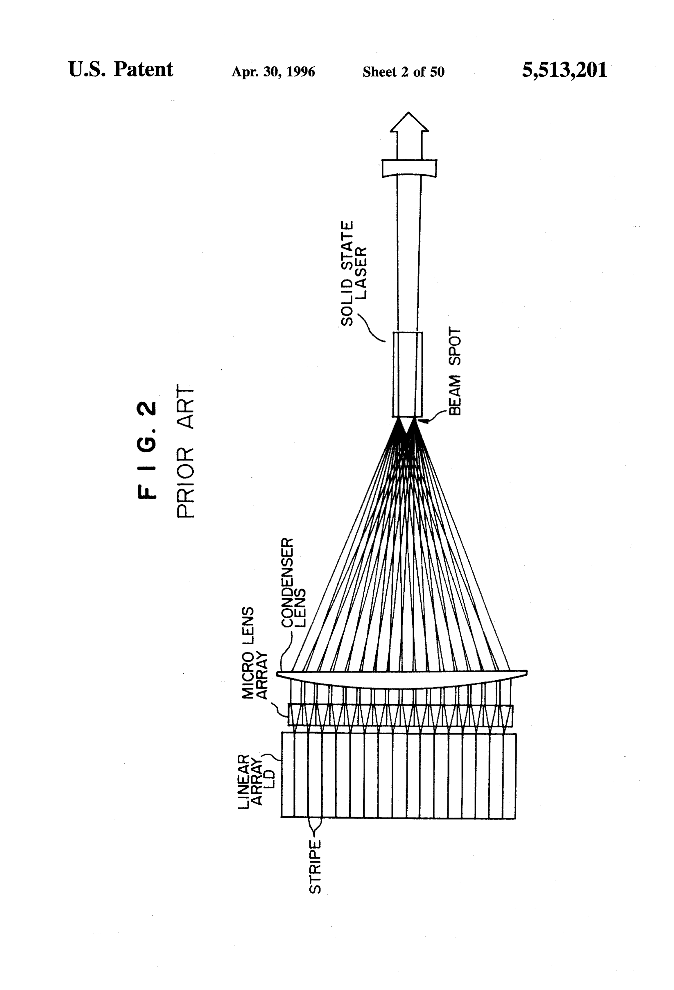
This invention relates to an optical path rotating device However, in this case, there is a great coupling loss of the and a laser apparatus using this optical path rotating device. 10 optical fiber. In addition, the horizontal components of the More particularly, this invention relates to a semiconductor LD beams cannot be condensed to an area smaller than laser condenser for condensing semiconductor laser beams several millimeters, so that some method needs to be con into a small spot and a semiconductor-laser-pumped solid trived, such as distorting the surface of the solid state laser state laser apparatus in which solid state laser elements are resonator to match it with the pump space. On the other optically pumped. 15 hand, Yamaguchi et al. disclose in JP-A-04-078179 (which 2. Description of Related Art corresponds to U.S. patent application Ser. No. 07/828,347 The YAG laser has been used for laser processing or by the same assignee of the present patent application) that medical applications. However, the YAG laser, which is a as shown in FIG. 2, micro lenses are arranged on a one-to solid state laser, has a low electro-optic conversion effi one correspondence with the stripes, and after condensing ciency. The reason is that only a small portion of emission 20 and collimating the beams from the stripes, this plurality of energy can be used to pump the solid state laser because in beams is condensed and superposed on one another by a the conventional YAG laser, the luminous efficiency of a Xe condenser lens, and by this method, the beams can be lamp or a flash lamp used for pumping the solid state laser converged upon a relatively small area. However, the con is low and the spectrum width of light emission is wide. verged beam spot diameter is a value obtained by multiply Therefore, the equipment has to be large in size and nor 25 ing the light source width by the magnification (fff) mally requires cooling water. determined by the ratio of the distance between the con On the other hand, the semiconductor laser (LD) has a denser lens and the beam spot (i.e., the focal length f, of the high conversion efficiency, is compact in size and does not condenser lens) to the distance between the semiconductor require an extensive cooling system. Recently, the cost of laser stripes and the micro lens array (i.e., the focal length high output semiconductor lasers is decreasing notably. It is 30 f, of the micro lenses). Therefore, the length w (horizontal desirable to use semiconductor lasers even in the field of component) of the beam spot is a value (Co6f/f) obtained by laser processing. However, the semiconductor lasers are multiplying the width of a stripe (a)0: 100-200 um) by the generally inferior in laser beam quality, and, furthermore, the above-mentioned magnification. The vertical component of there is a limit to enlarging the output of the single-striped beam spot does not amount to a large diameter when the semiconductor laser, so that it is difficult to use the semi 35 width of the vertical component of the light source is conductor laser as is for laser processing. A multi-stripe multiplied by the same magnification (f/f) because the array semiconductor laser having arranged linearly therein vertical width is very small (no more than 1 um). Therefore, 10 to 100 active layer stripes to serve as a broken-line in view of the light convergence in the width direction of the shaped light source for emitting laser beams is known as a stripes, in order to increase the light intensity by reducing high output laser. 40 the beam spot, it would be better to arrange the micro lenses As for semiconductor lasers of a linear array type having as distant from the stripes as possible. However, this is active layer stripes arranged linearly, CW (continuous wave) difficult to realize because the radiant energy leaking out of the lens apertures located at a distance from the stripes is lasers with high optical power of 20 W are now available on large owing to the large divergence angle of the vertical the market. In a multi-stripe array semiconductor laser, as 45 components of the stripe beams.
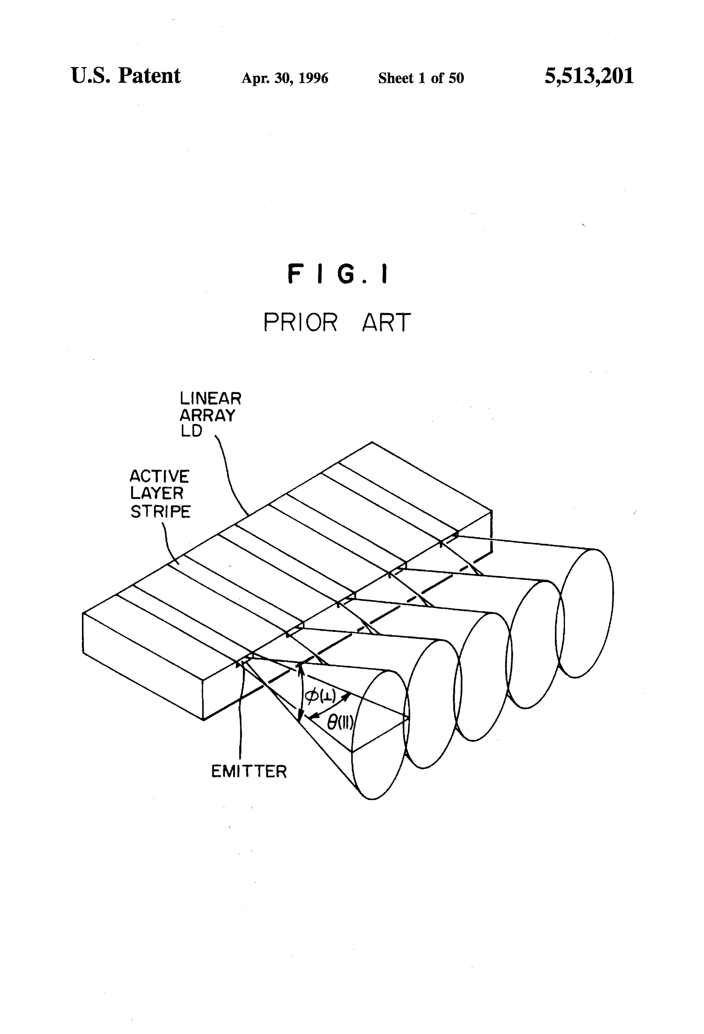
shown in FIG. 1 for example, ten to several tens of 100-200 A possible solution is to condense the vertical components um wide stripes having emitters at their ends are arranged at and the horizontal components by separate cylindricallenses fixed intervals within a flat face of the laser having a total and by arranging the lens for condensing the vertical com width of about 1 cm.
ponents close to the stripes and the micro cylindrical lenses
As described above, one piece of semiconductor laser 50 for condensing the horizontal components remote from the element provides a light source composed of line segments stripes. The micro cylindrical lenses are provided on a for emitting ten to several tens of laser beams arranged in one-to-one correspondence with the stripes. A typical LD line. Some means for condensing a high-level energy in a stripe array product available on the market is one which has narrow area should be contrived in order to apply the multi-stripe array semiconductor laser to laser processing or 55 arrangedstripes twelve
having 1 um thickness and 200 um width um pitches. The adjacent horizontal com medical applications. ponents of the beams from the stripes, each having a beam Each stripe beam is emitted from a flat light source, and divergence angle of 10 overlap each other at about 3.4 mm with reference to the divergence angle of the beam, the from the emitter end of the stripes. If the micro lenses are vertical component () in relation to the active layer is about placed beyond this overlapping point, part of the beams as wide as 40 to 50 degrees, while the horizontal component 60 travel at a certain angle from the axes of the lenses, and 8 is about as small as 10 degrees. With reference to the converge at a point different from the focus of the focusing widths of each light source, the vertical component is narrow lens, so that the efficiency of the system is reduced. There with up to 1 um, while the horizontal component is wide fore, in order to collimate the beams from the stripes by with 100 to 200 um as mentioned above. using a micro cylindrical lens array, it is necessary to place Due to the characteristics of the semiconductor laser 65 the lenses at a position less than 3.4 mm away from the mentioned above, when the emitted beams from the semi stripes (focal distance f s3.4 mm). The converged spot conductor lasers are condensed and converged with lenses, diameter is inevitably large when the spot diameter is
Page 53
estimated by multiplying the stripe width by the magnifica and a focusing element for condensing the laser beams tion (fff) determined by involving the focal distance f of collimated in two directions.
the condenser lens for condensing the collimated beams. The laser beams from the long and narrow emitters, As has been discussed, it has been difficult to focus the arranged like a dotted line, of the linear array laser diode laser beams in the form of a broken line emitted from the have a small divergence angle in the longitudinal direction linear array of LDs in a small area at a high energy density. of the emitters and a large divergence angle in the direction According to an end surface pumping method for opti perpendicular to the emitters, and therefore unless different cally pumping the solid state laser in the direction of its focusing powers are applied to these two directions, the optical axis in a semiconductor-laser-pumped solid state 10 radiant area. As energy cannot be concentrated in a sufficiently small described above, the divergence angle of the laser laser, a highly efficient emission of single fundamental beam is small in the width direction of the laser diode and transverse mode can be realized by matching the pumping moreover the whole width of the laser beams emitted from space by a semiconductor laser output light width the mode the linear array laser diode is large in accordance with the space of solid state laser oscillation. width of the linear array laser diode. Therefore, it is difficult A multi-stripe array semiconductor laser element having 15 to concentrate the radiant energy in a small area. In the semiconductor laser active layers arranged in a line produces semiconductor laser apparatus of the present invention, output power of 10 W or more which is sufficient for laser however, the laser beams from the long and narrow emitters, micro processing. If the multi-stripe laser beams can be arranged like a dotted line, of the linear array laser diode are converged directly into a sufficiently thin spot by using an received by the first collimating element, which changes the optical system, the semiconductor laser output should be 20 beams into substantially collimated beams in planes perpen able to be directly used for laser beam machining. dicular to the emitters by refracting the beams to a direction However, as described above, when the emitted beams perpendicular to the emitters. The light beams are incident from the semiconductor laser generating element are con on the optical path rotating device, and while their advanc densed and converged by lenses, the vertical components of ing directions are changed, the directions corresponding to the beams may be converged into a small spot, but it is 25 the transverse axes of the emitters are rotated substantially difficult to converge the horizontal components in small up to a right angle. The beams emitted with anisotropical areas since the whole width of the light sources is so large. divergence are, as they pass through the second collimating When such a linear array semiconductor laser is used as element, refracted by different condensing powers of the a pumping light source, as the array width reaches around 1 second element to a direction perpendicular to the transverse cm, a plurality of light beams cannot be converged into a 30 axes of the emitters to become substantially parallel beams, small spot by an ordinary optical system, and for this reason, and then focused to a spot by the focusing element. For this the end pumping method which is excellent in pumping reason, the semiconductor laser apparatus which converges efficiency cannot be adopted, and therefore a side surface the laser energy produced by the linear array laser diode into pumping method could only be used with this linear array a very small area can be used for laser processing or for semiconductor laser as the light source. 35 medical purposes.
In order to achieve the above objects, the optical path rotating device of the present invention comprises a plurality
SUMMARY OF THE INVENTION of optical elements, each receiving a beam emitted in the Therefore, it is an object of the present invention to 40 of form of a slit, rotating the slit direction in the cross section provide a semiconductor laser apparatus with an increased the beam substantially by a right angle about the optical energy density at the light focus of the semiconductor laser axis and emitting the beam, wherein the light receiving faces apparatus which uses a linear array semiconductor laser. and the light emitting faces of the optical elements are Another object of the present invention is to provide a arranged in a line respectively without space between adja cent elements in such away that each of the optical elements novel optical path rotating device to be used in a semicon 45 faces a corresponding ductor laser apparatus incorporating a linear array semicon light-emitting face or a group of the ductor laser which enables an increase in the energy density light-emitting faces of the linear array laser diode. In other by minimizing the light focusing area of the semiconductor words, the optical path rotating device of the present inven laser apparatus. tion is arranged to rotate by a substantially right angle about the optical axis the directions corresponding to the emitters
Yet another object of the present invention is to provide a 50 of the laser beams emitted from the line-shaped emitters or powerful semiconductor-laser-pumped solid state laser groups of emitters of the linear array semiconductor laser. apparatus by using the above-mentioned semiconductor When the optical path rotating device of the present inven laser apparatus. tion is disposed in front of the linear array semiconductor In order to achieve the above objects, the semiconductor laser, the optical elements of the device receive the laser laser apparatus according to the present invention comprises 55 beams emitted from the emitters or the groups of emitters, a linear array laser diode having a plurality of long, narrow and rotate the directions corresponding the transverse axis of emitters for emitting laser beams arranged in a line in the the emitters of the laser beams by a right angle around the lengthwise direction; a first collimating element for colli optical axis. Therefore, in the laser beams output from the mating the laser beams emitted by the emitters or groups of optical path rotating device, component beams from the the multiple emitters in a direction perpendicular to the 60 respective optical elements have the directions correspond lengthwise direction of the emitters; an optical path rotating ing the transverse axis of the emitters rotated by a right device for rotating by a right angle the emitter length-wise angle, that is, as many beams as the optical elements are axis of the cross section of each laser beam collimated only arranged side by side like the rungs of a ladder. Conse in one direction and outputting the rotated laser beams; a quently, the results can be obtained as if the emitters of the second collimating element for collimating the laser beams 65 linear array semiconductor laser were arranged like the output from the optical path rotating device in a direction ladder rungs. It is easy to focus the beams in a direction corresponding to the lengthwise direction of the emitters; perpendicular to the transverse axis of the emitters, and it is
Page 54
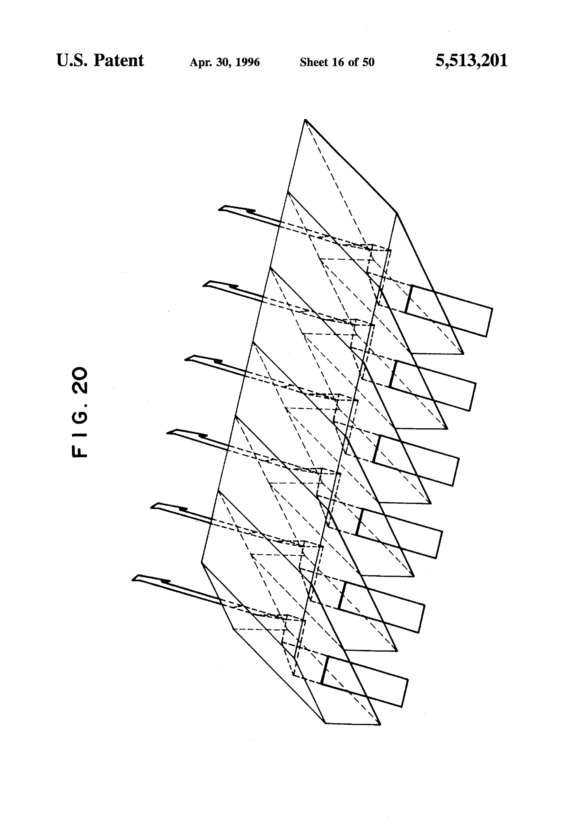
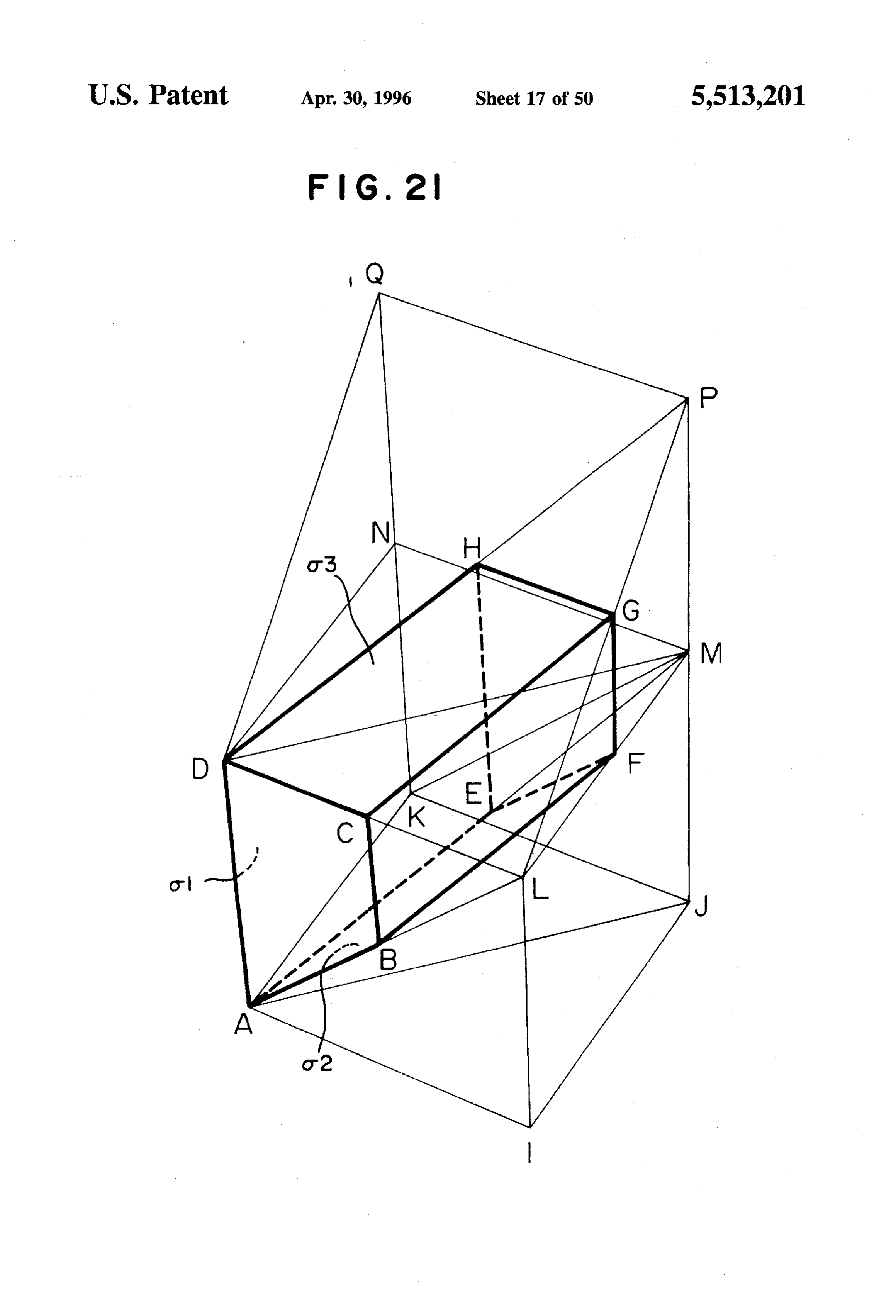
also easy to converge the beams from the parallel emitters FIG. 18 is a perspective view showing an optical element lined up like ladder rungs at a very small area. Therefore, a formed by an oblique prism having three reflecting faces; semiconductor laser apparatus which offers effects of sub FIG. 19 is a diagram for explaining the principle of the stantially arranging the emitters of the linear array semicon oblique prism;
ductor laser in the form of ladder rungs by using the optical FIG. 20 is a perspective view of the optical path rotating path rotating device of the present invention can concentrate device formed by having the optical elements of FIG. 18 the energy of the linear array semiconductor laser in a very arranged in parallel;
Small spot. FIG. 21 is a perspective view showing another optical Furthermore, the semiconductor-laser-pumped solid state element formed by an oblique prism having three reflecting laser apparatus of the present invention has the solid state 10 faces;
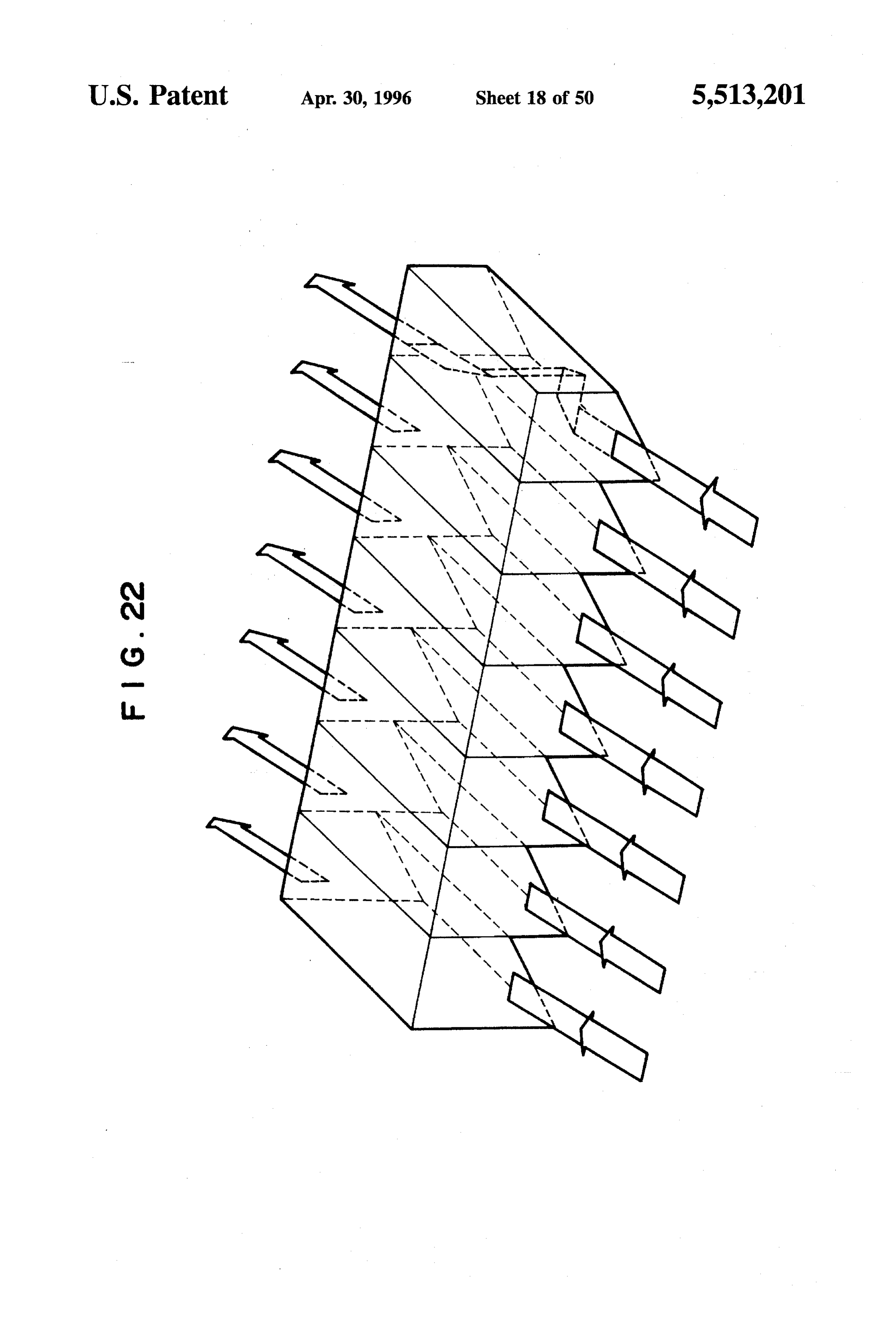
laser arranged its pumping-light-receiving end face at the FIG. 22 is a perspective view of an optical path rotating focus of the above-mentioned laser beams from the semi device formed by having the optical elements of FIG. 21 conductor laser apparatus. arranged in parallel;
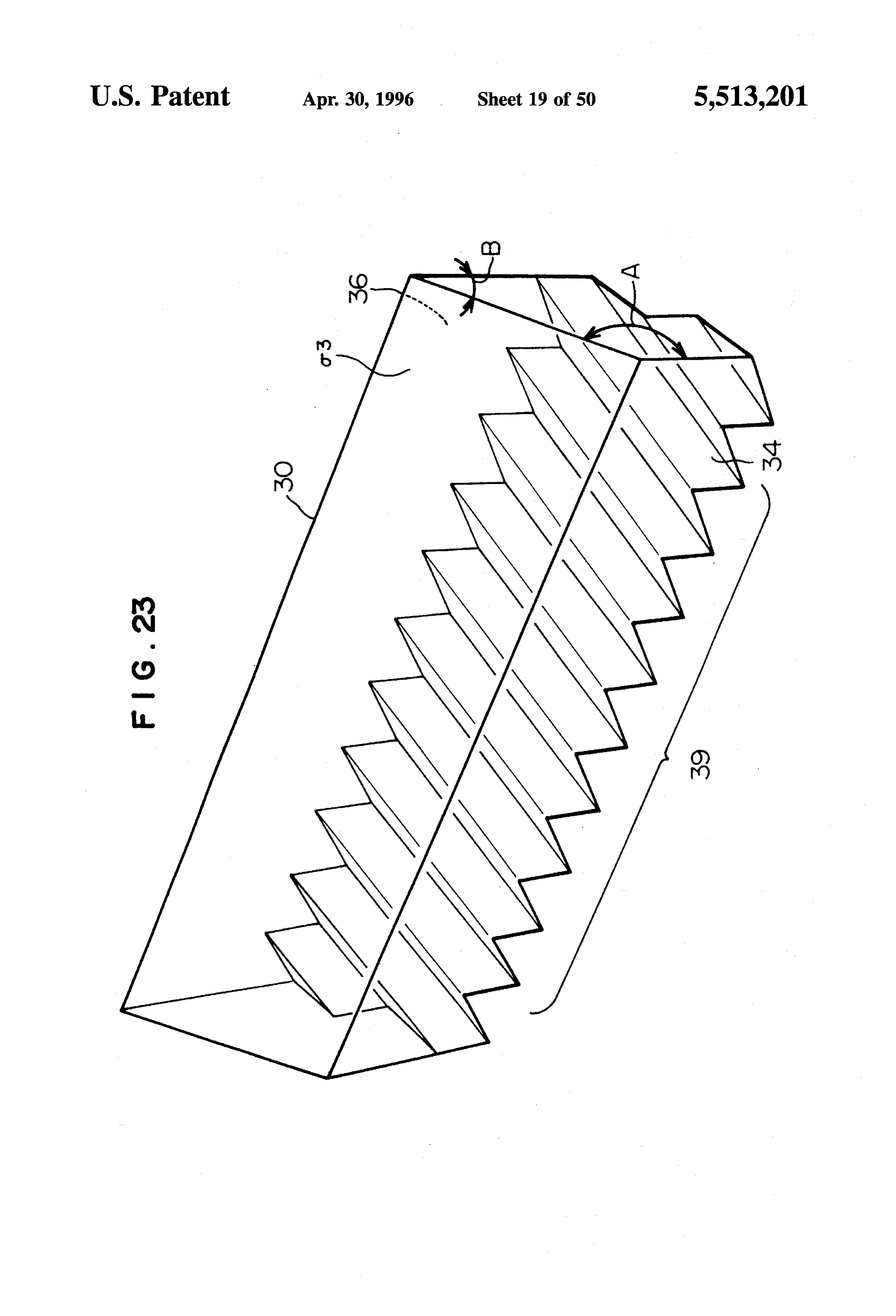
By the arrangement as described, the semiconductor 5 FIG. 23 is a perspective view of a monolithic optical path laser-pumped solid state laser apparatus of the present rotating device equivalent to the optical path rotating device invention is capable of end pumping by using a powerful of FIG. 22;
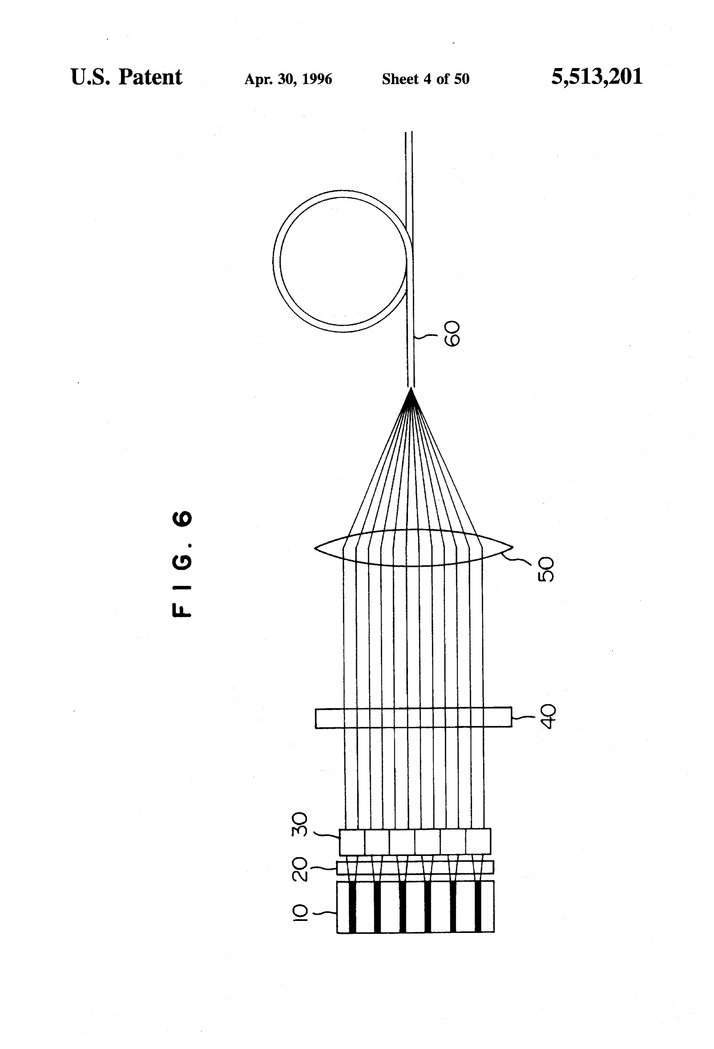
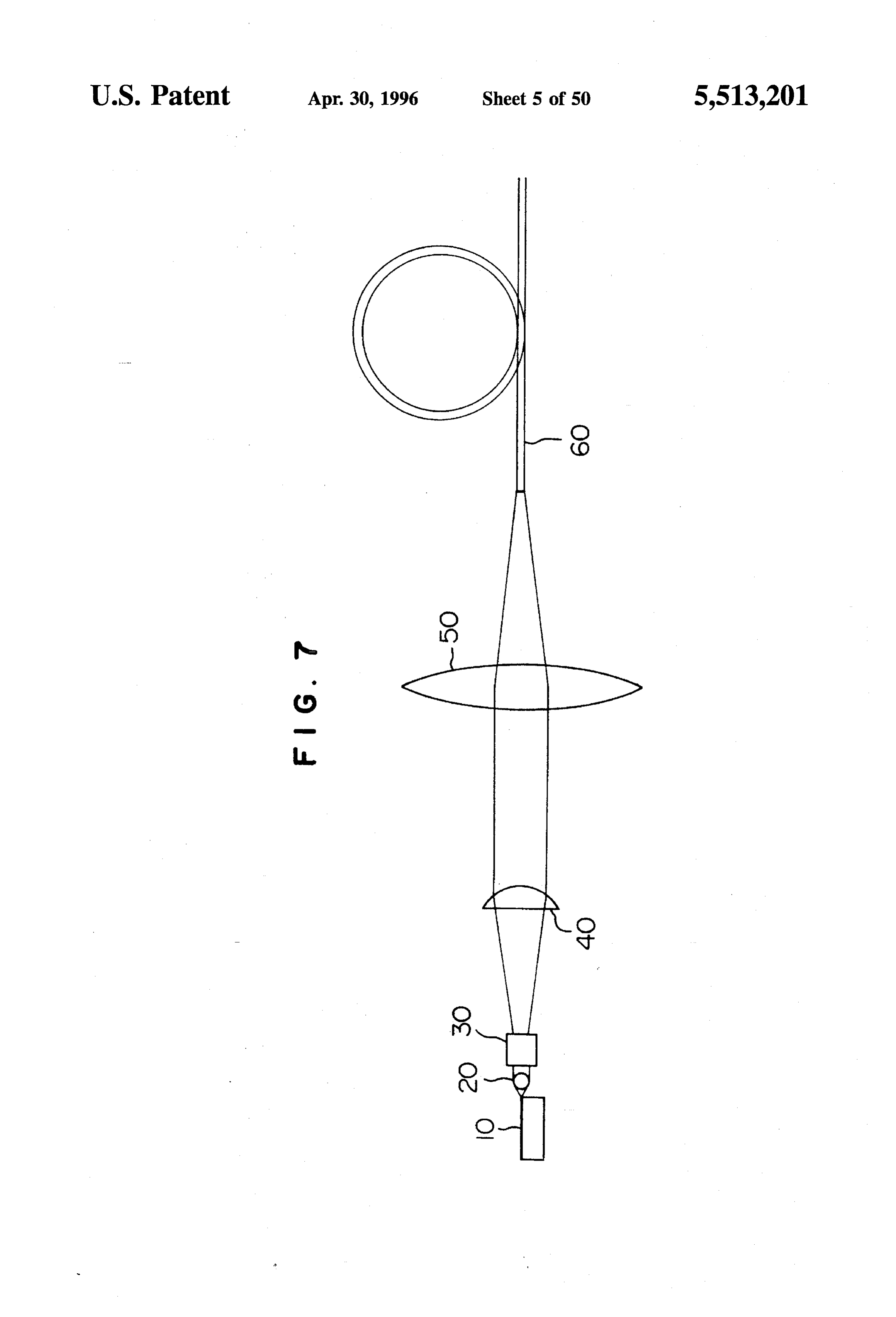
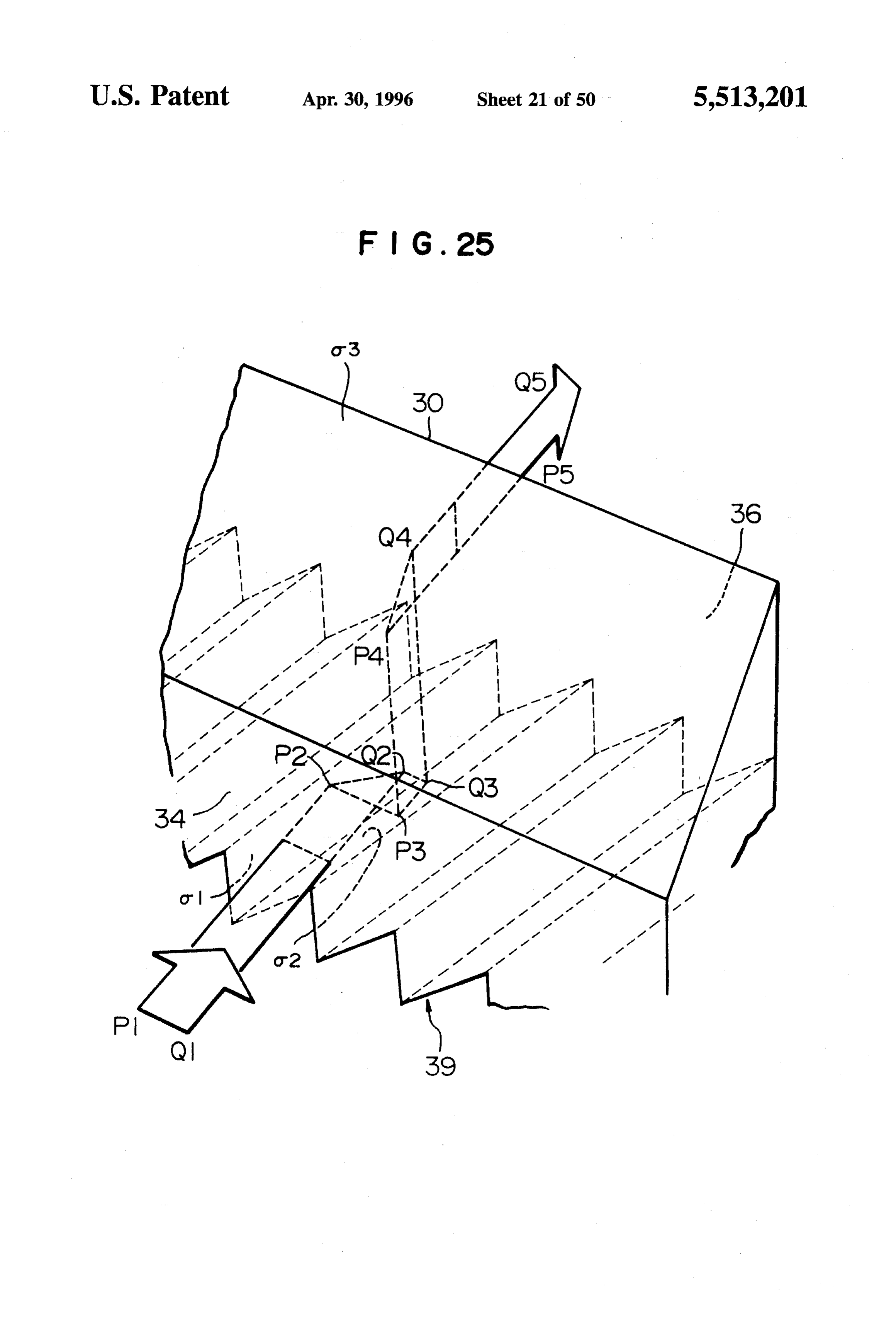
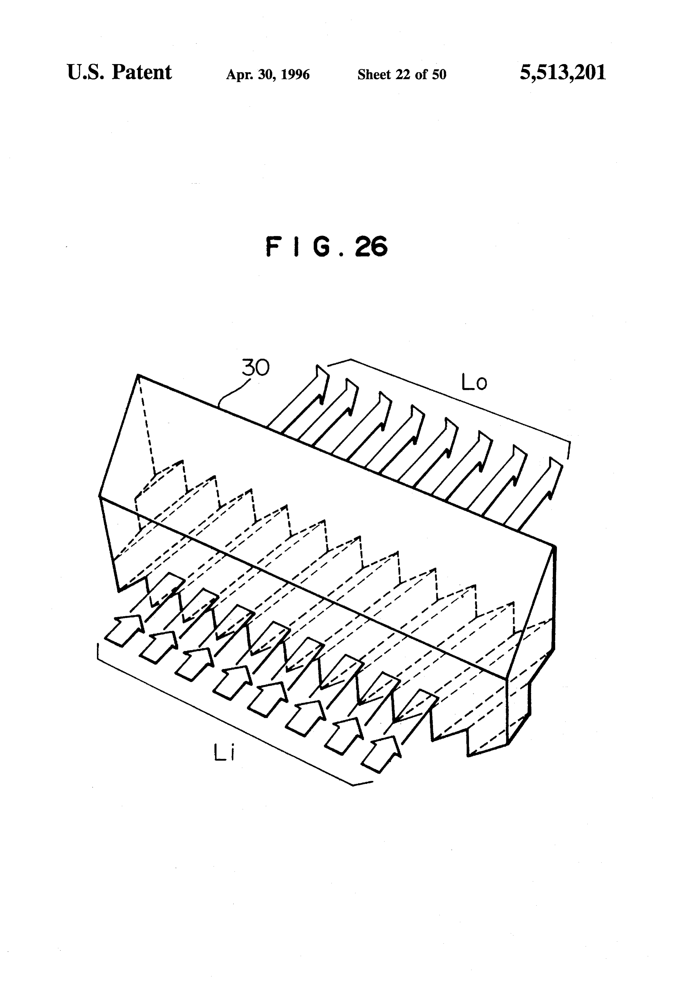
semiconductor laser, and therefore a solid state laser output FIG. 24 is a diagram for explaining a method for produc can be obtained with a good quality beam and with high ing the optical path rotating device of FIG. 23; efficiency. 20 FIG. 25 is a diagram for explaining the locus of a light BRIEF DESCRIPTION OF THE DRAWINGS beam in the optical path rotating device of FIG. 23; FIG. 26 is a diagram for explaining the function of the
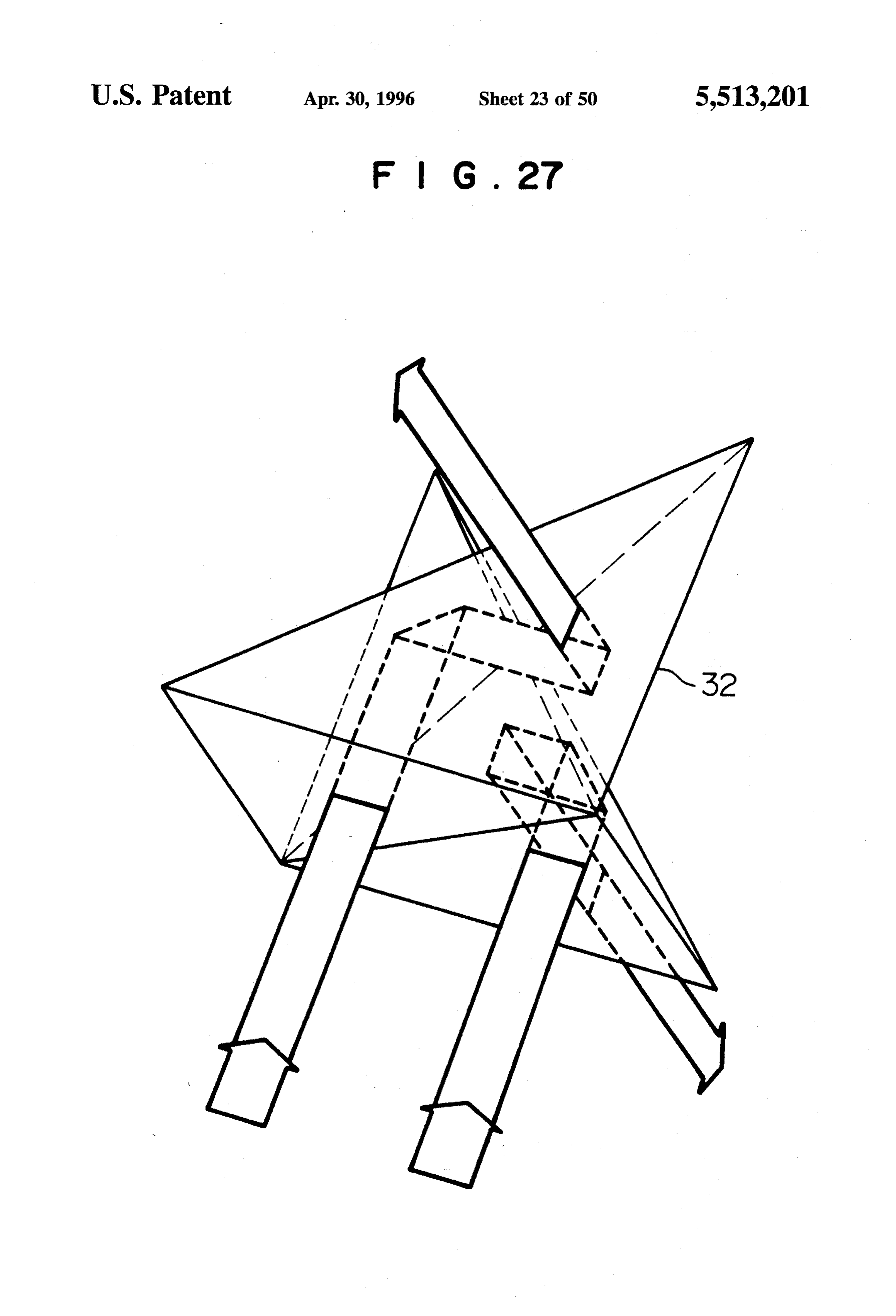
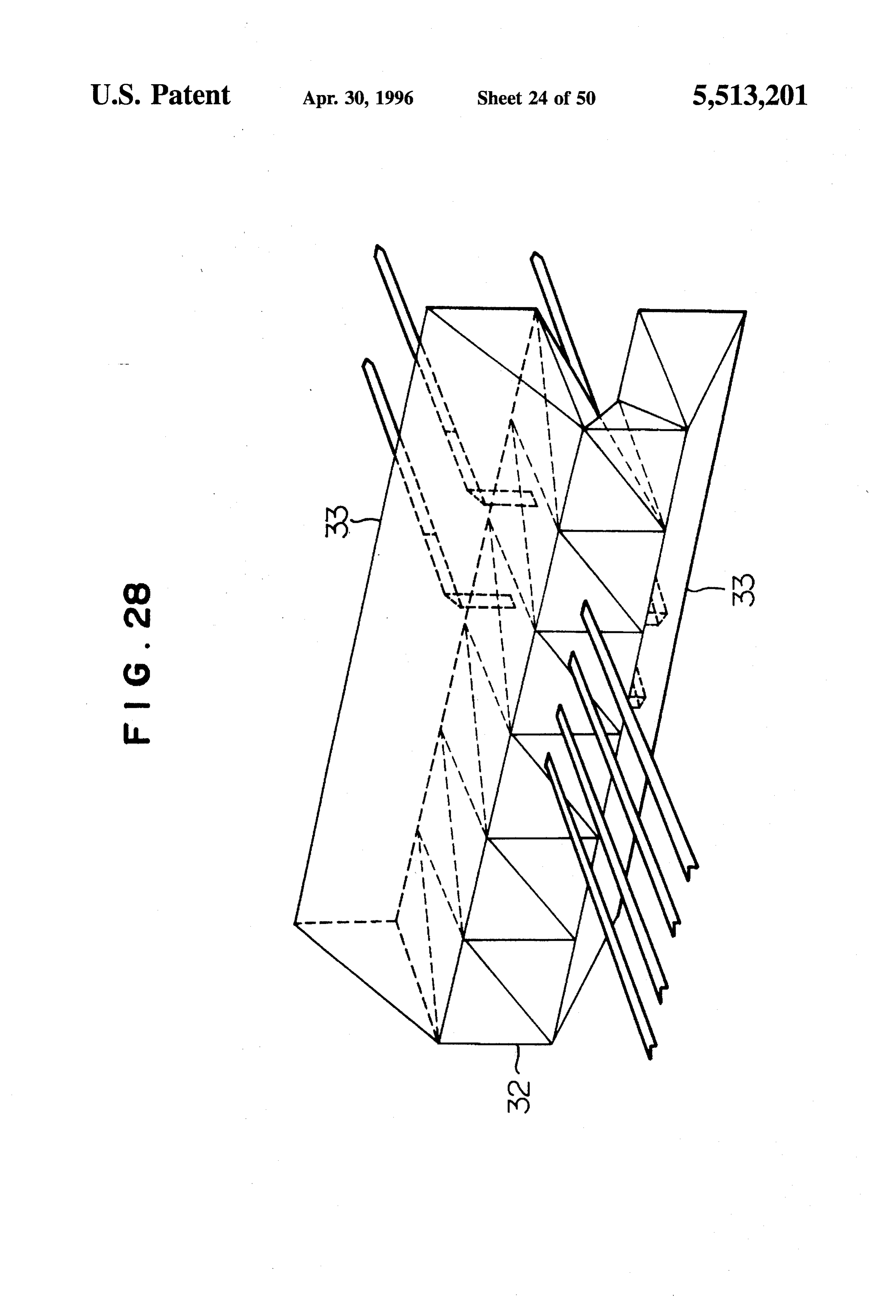
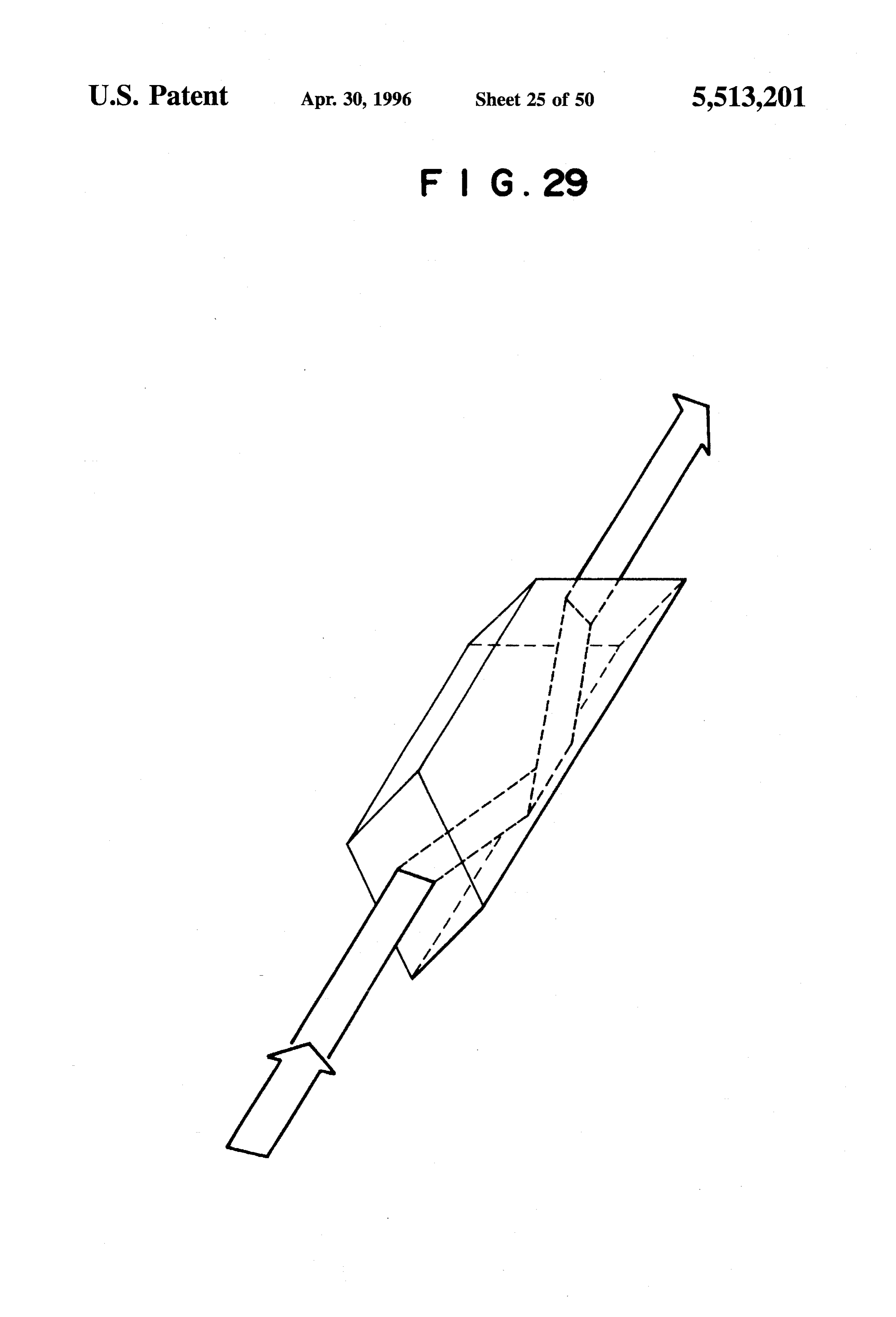
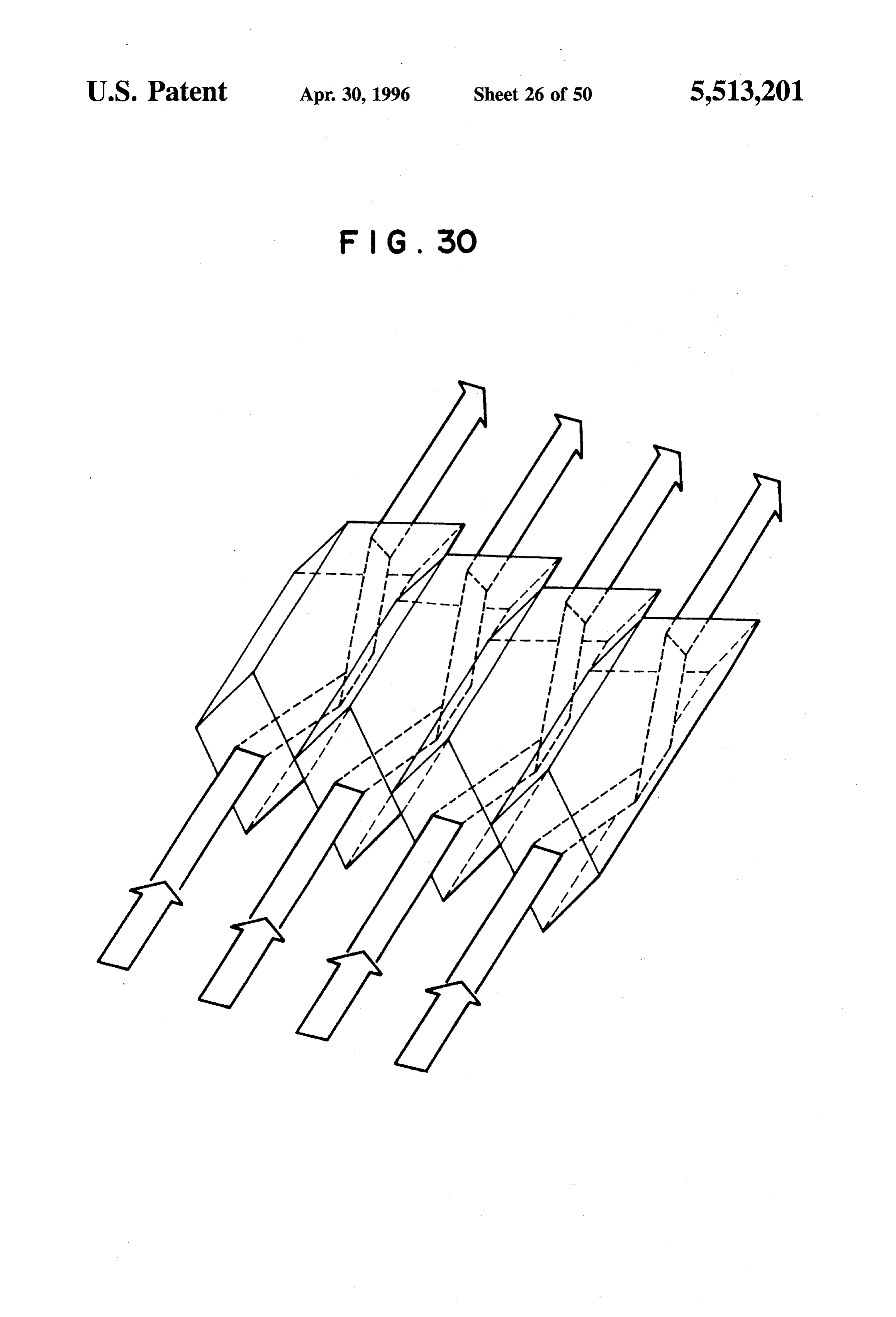
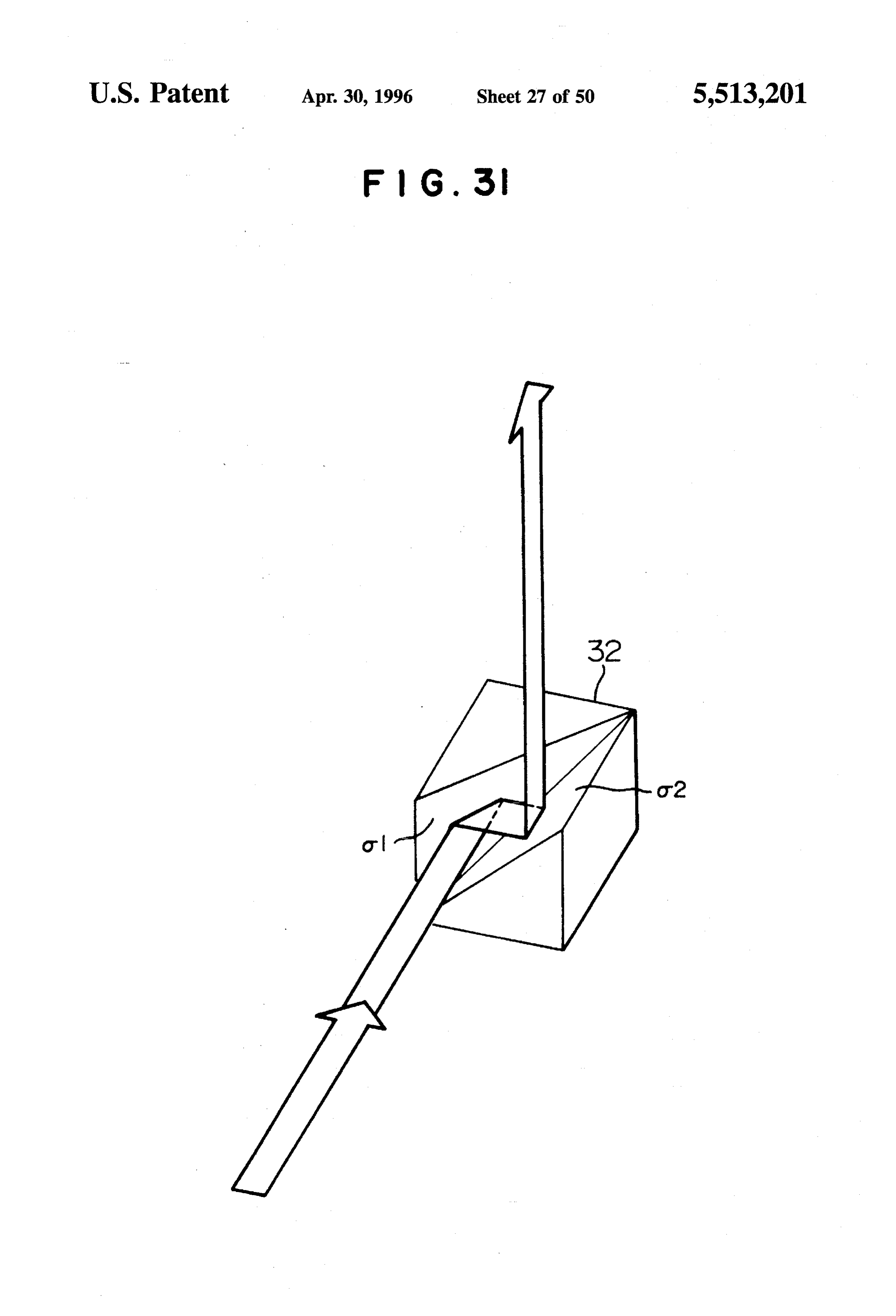
FIG. 1 is a diagram for explaining the directivity of laser optical path rotating device of FIG. 23; beams of a linear array laser diode; FIG. 27 is a perspective view showing an optical element FIG. 2 is a block diagram for explaining a semiconductor 25 formed by a composite prism having tetrahedron prisms laser apparatus of the prior art; combined symmetric with respect to the axis; FIG. 3 is a plan view of a semiconductor laser apparatus FIG. 28 is a perspective view of an optical path rotating of the present invention; device formed by having composite prisms of FIG. 27 FIG. 4 is an elevation of the semiconductor laser appa 30 arranged in parallel;
ratus shown in FIG. 3; FIG. 29 is a perspective view showing an optical element FIG. 5 is a pian view of the semiconductor laser apparatus formed by a dove prism;
of the present invention using QCWLD or the like; FIG. 30 is a perspective view of an optical path rotating FIG. 6 is a plan view of the semiconductor laser apparatus device formed by having dove prisms arranged in parallel; of the present invention using optical fiber; 35 FIG. 31 is a perspective view of an optical element, FIG. 7 is an elevation of the semiconductor laser appa corresponding to the one in FIG. 12, which utilizes reflective ratus shown in FIG. 6; mirrors;
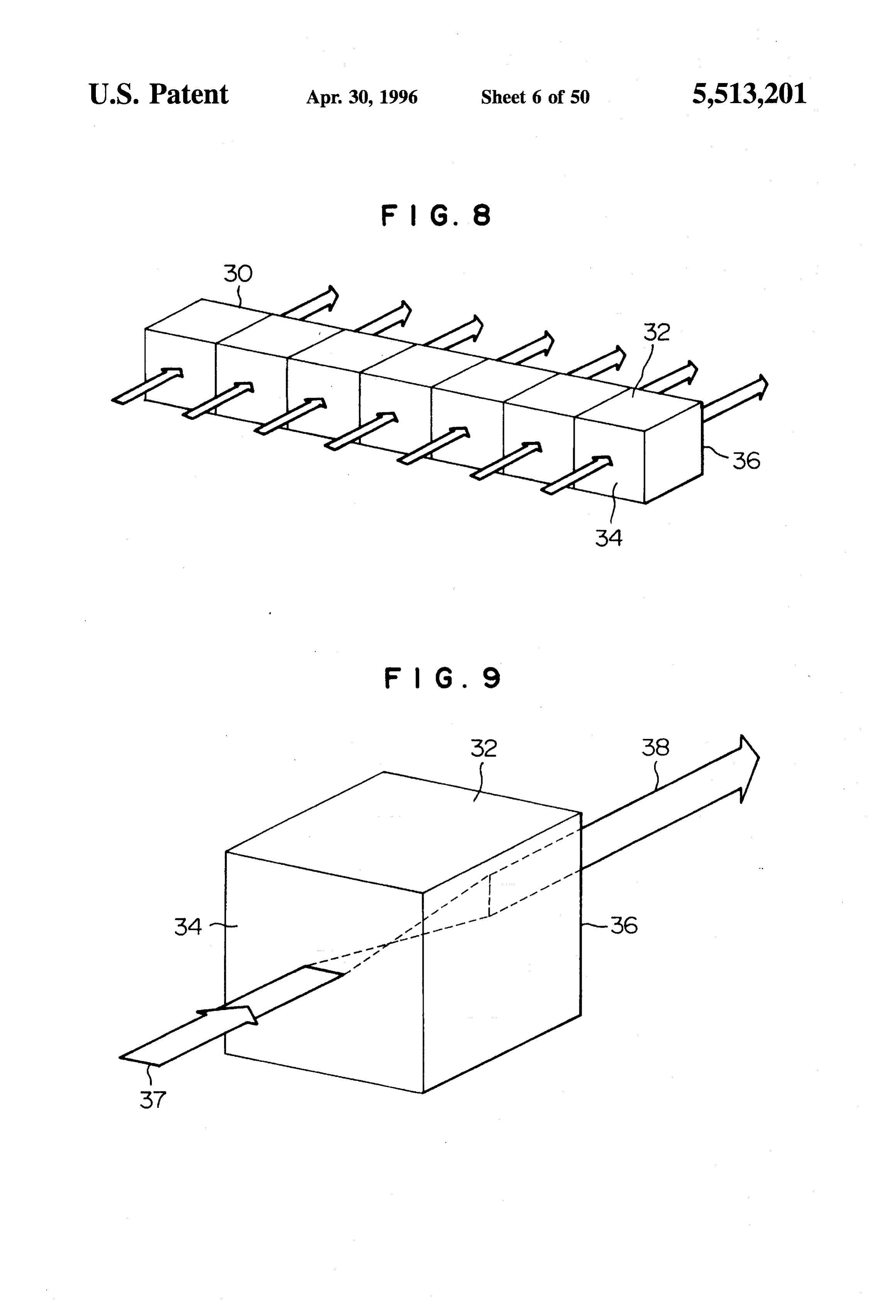
FIG. 8 is a block diagram for explaining an optical path FIG. 32 is a perspective view of an optical path rotating rotating device of the present invention; device, formed by having the optical elements of FIG. 31 FIG. 9 is a block diagram for explaining the function of 40 arranged in parallel;
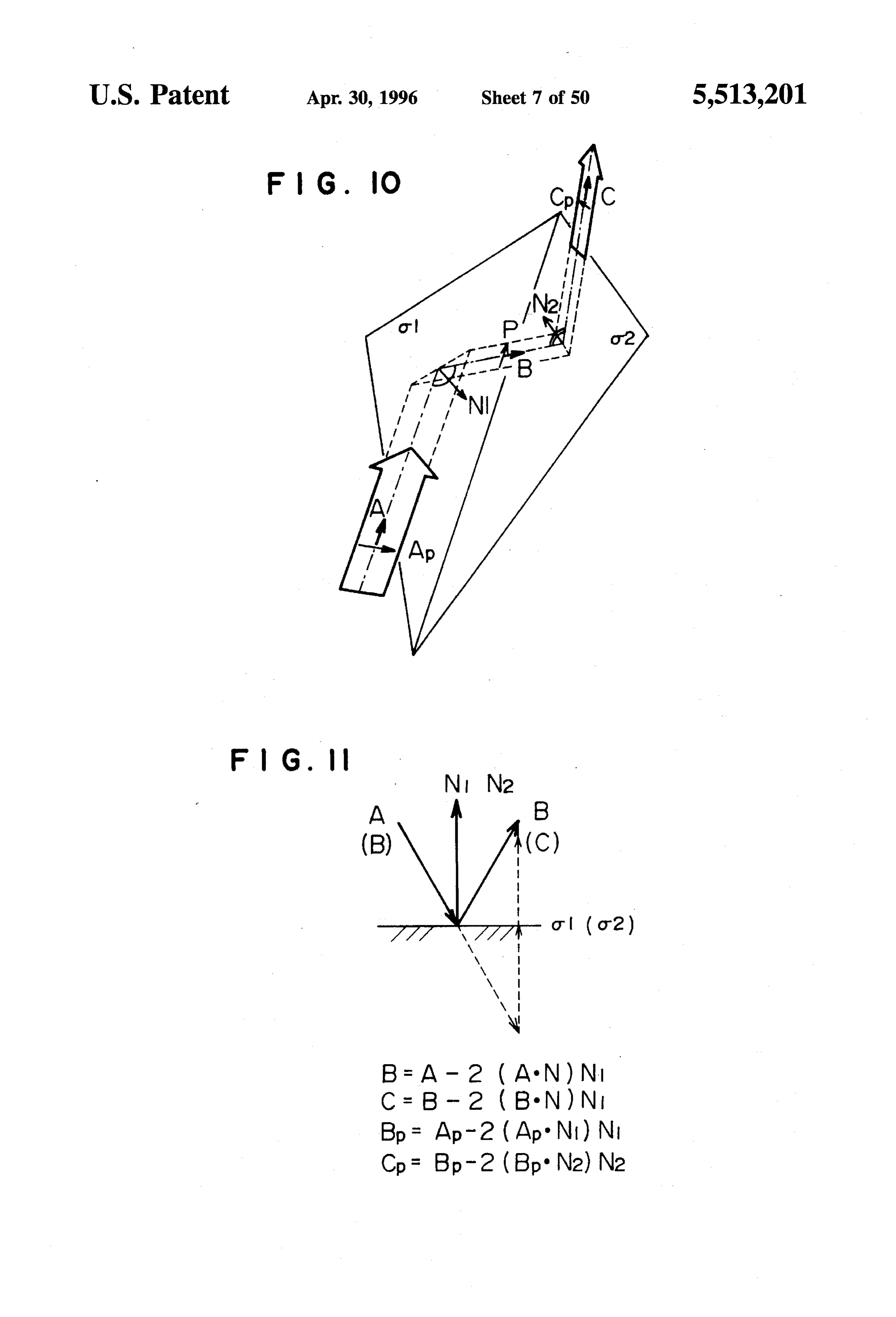
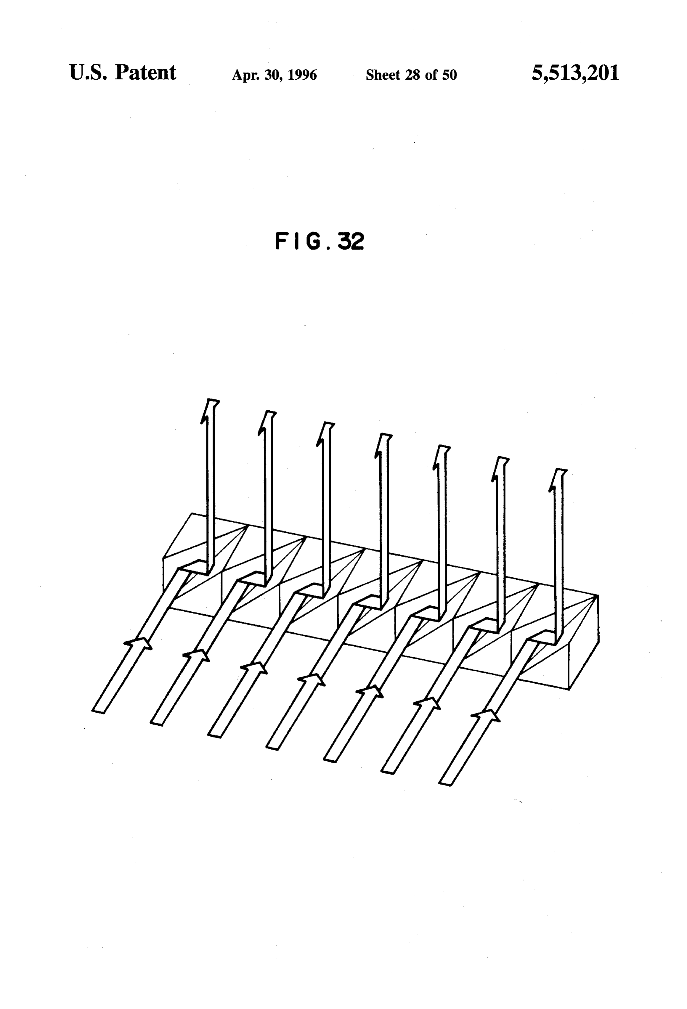
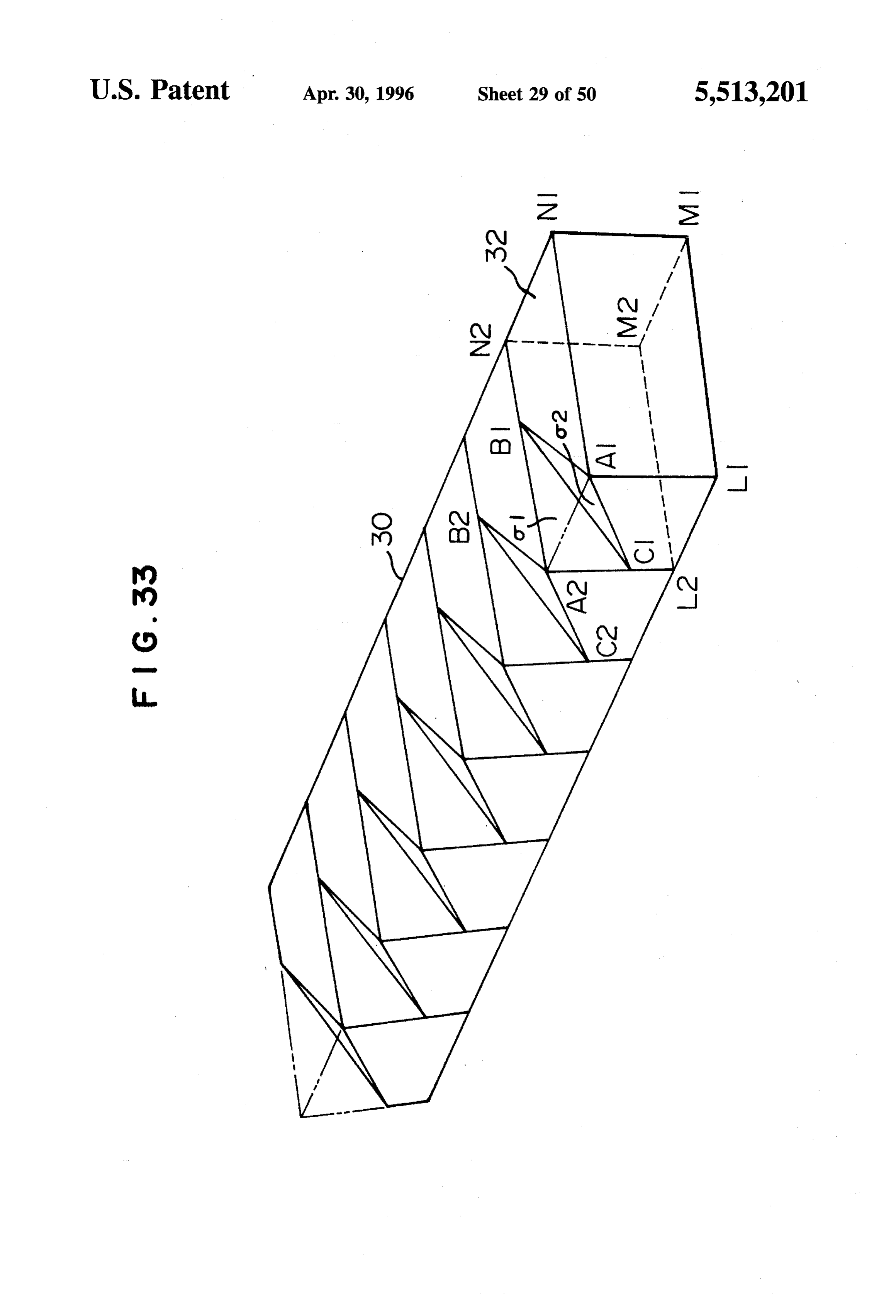
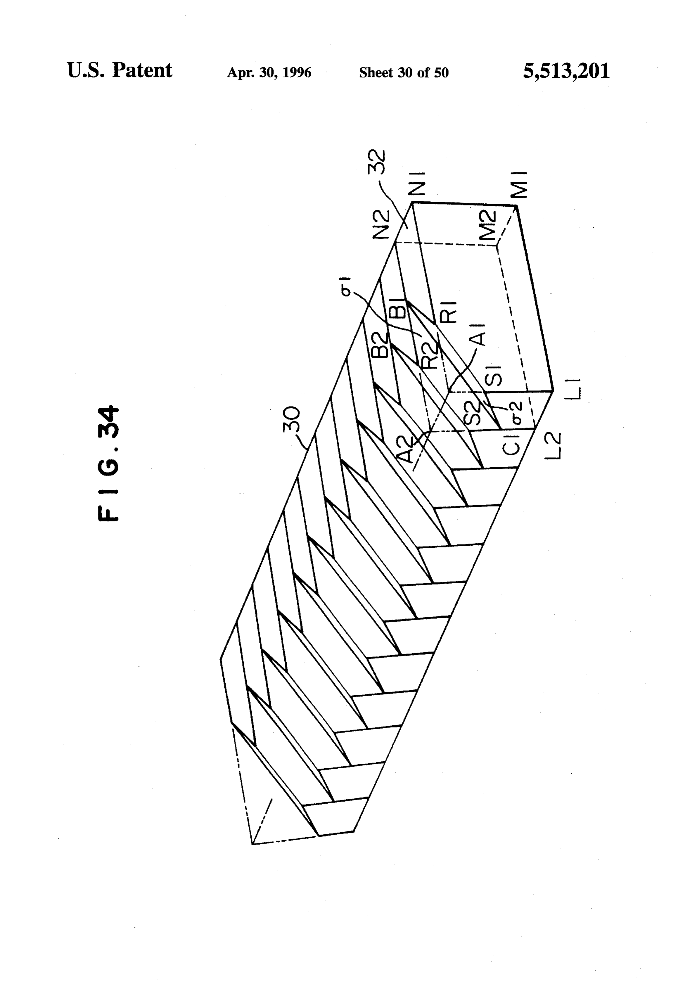
an optical element as a component of the optical path FIG. 33 is a perspective view of another optical path rotating device; rotating device formed by having the optical elements, FIG. 10 is a diagram for explaining the principle of a case corresponding to the one in FIG. 12, which utilize reflective where the optical path is rotated by a combination of two 45 mirrors;
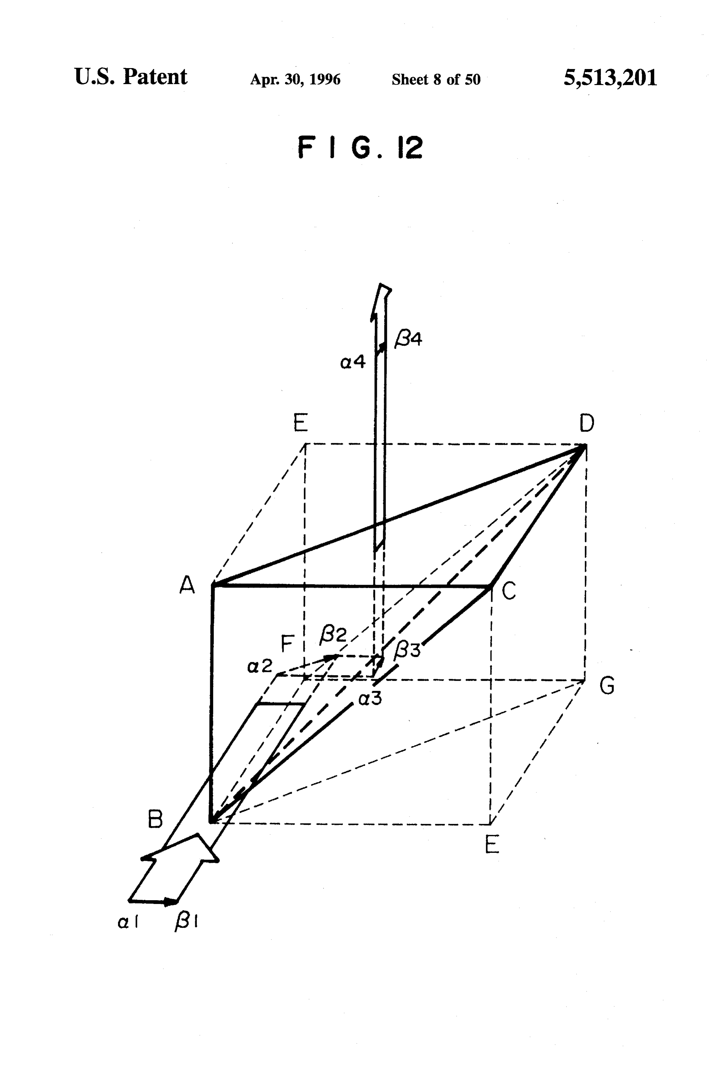
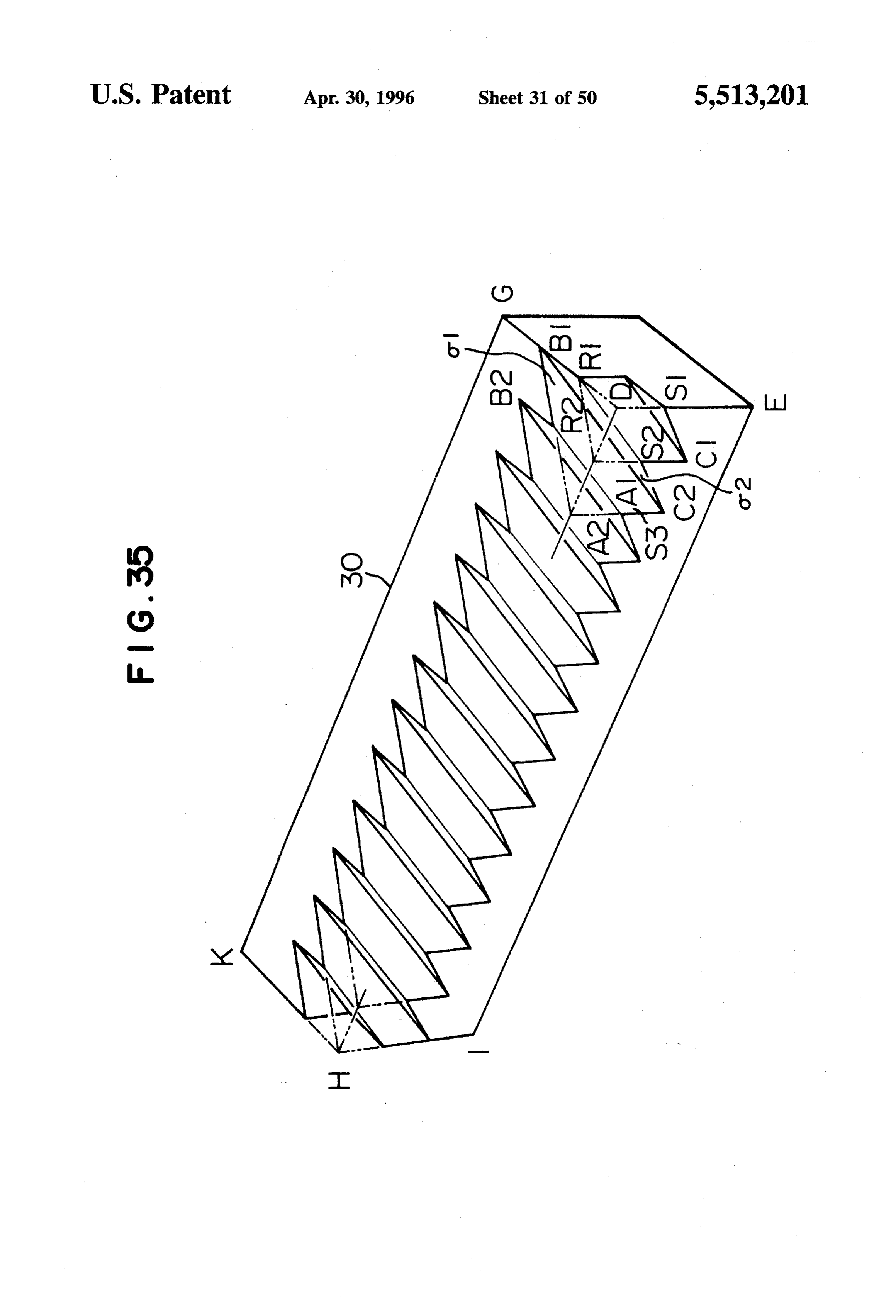
reflecting faces; FIG. 34 is a perspective view of the optical path rotating FIG. 11 is a diagram for explaining the conditions of device of FIG. 33 which have had notches deepened; reflection on the reflecting face; FIG.35 is a perspective view of a monolithic optical path FIG. 12 is a perspective view of an optical element in the rotating device equivalent to the optical path rotating device form of a tetrahedron; 50 of FIG. 34;
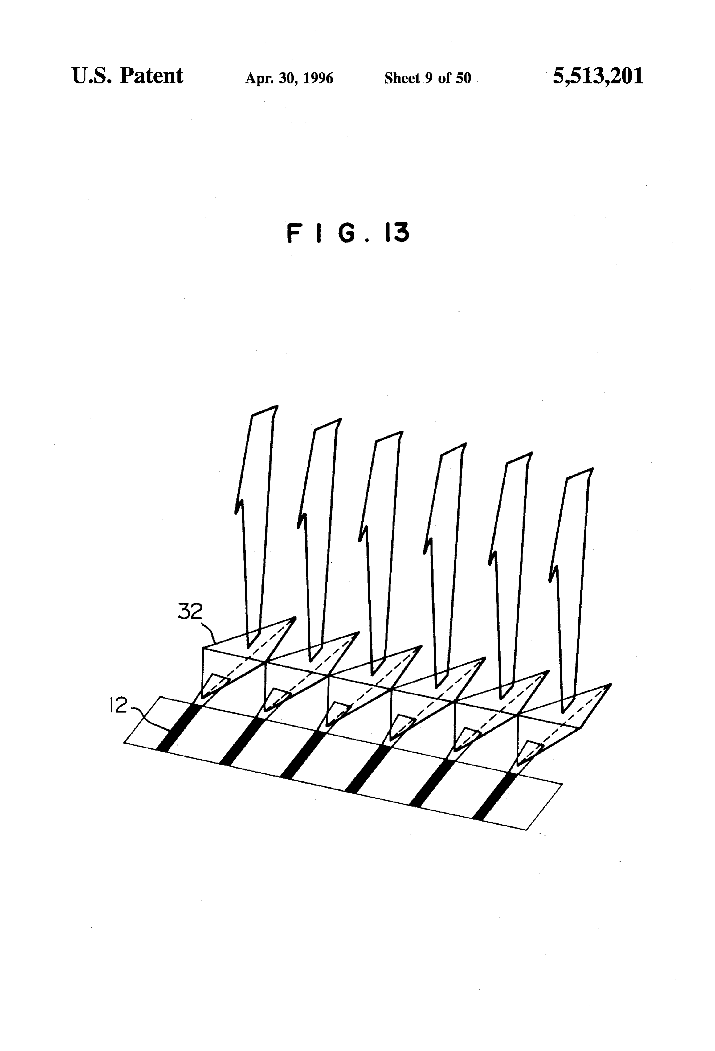
FIG. 13 is a perspective view of an optical path rotating FIG. 36 is a perspective view of an optical path rotating device of the present invention having the optical elements device formed by attaching a right angle prism to the optical in FIG. 3 arranged in parallel; path rotating device of FIG. 35;
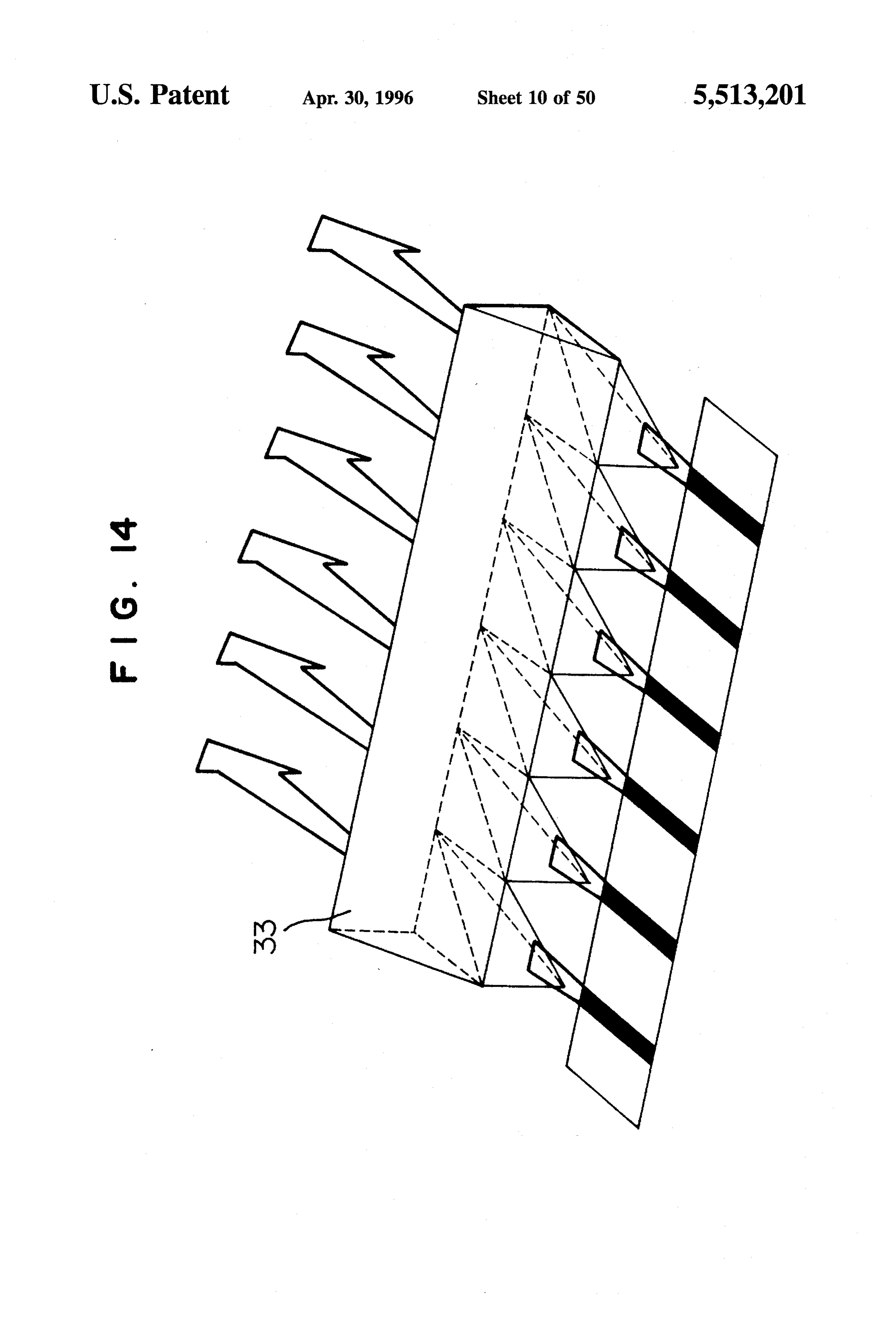
FIG. 14 is a perspective view of the optical path rotating 55 FIG. 37 is a perspective view partly in section showing a device of the present invention, formed by having the optical portion of the optical path rotating device formed by pro path rotating device of FIG. 13 added with a right angle viding a third reflective mirror on top of the optical path prism, rotating device of FIG.35;
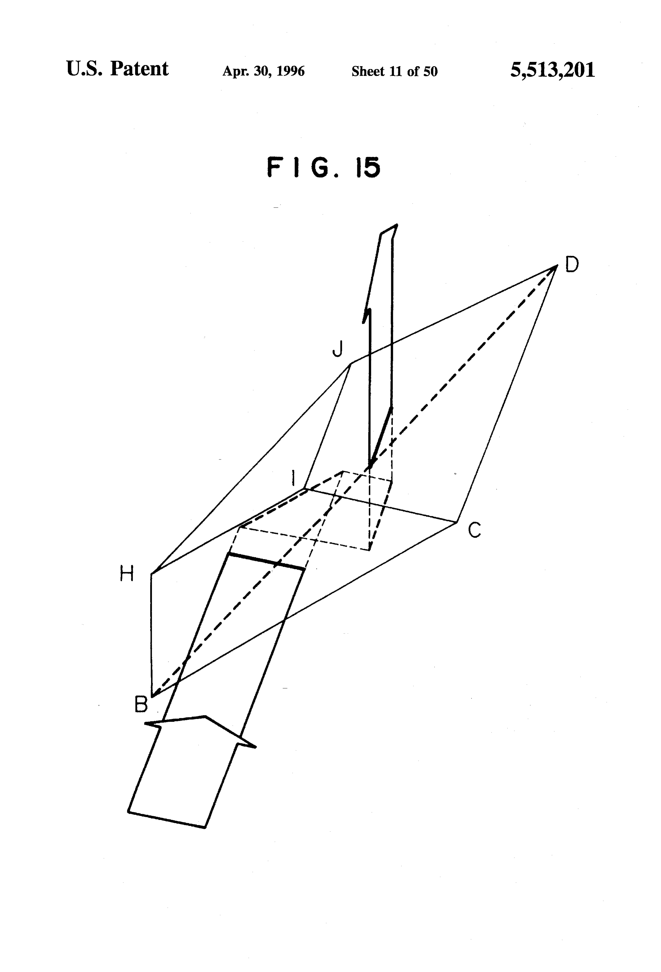
FIG. 15 is a perspective view showing an optical element FIG. 38 is a perspective view of an optical path rotating shaped in the form of a frustum of tetrahedron; 60 device formed by mounting a plurality of optical elements
FIG. 16 is a perspective view of the optical path rotating on a transparent disc;
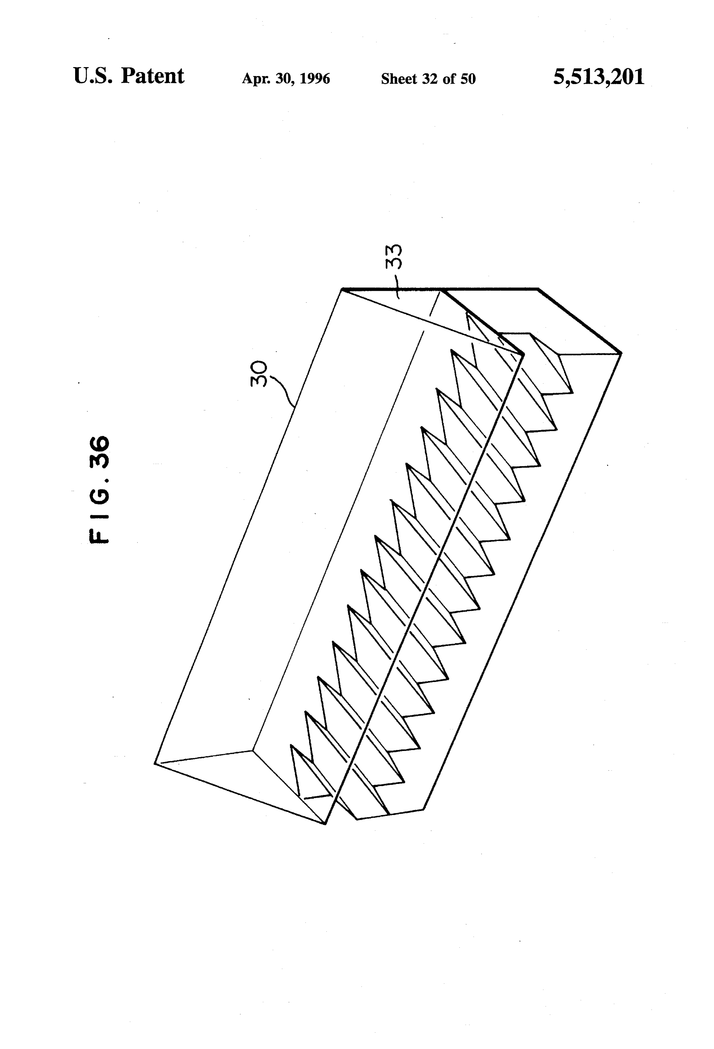
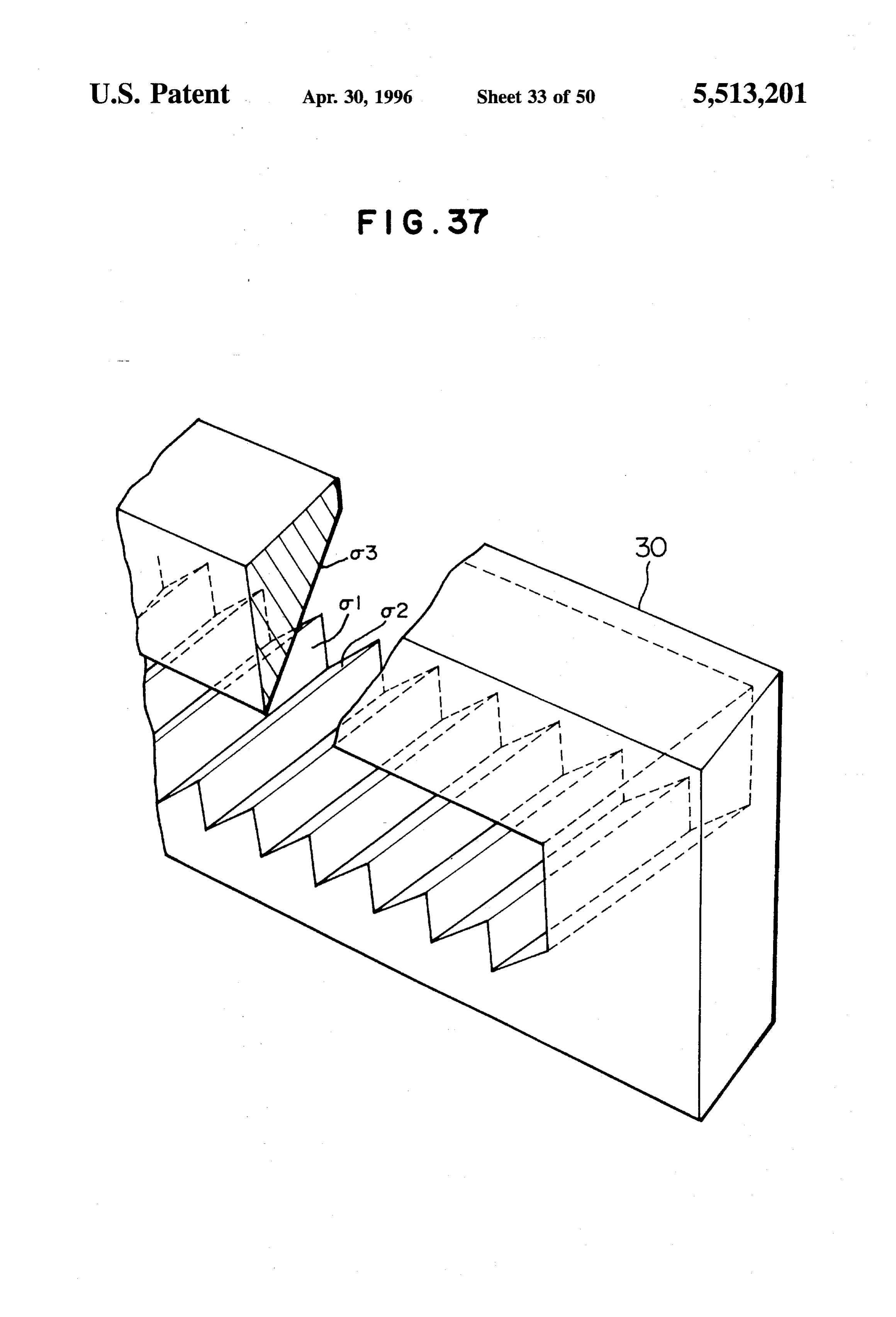
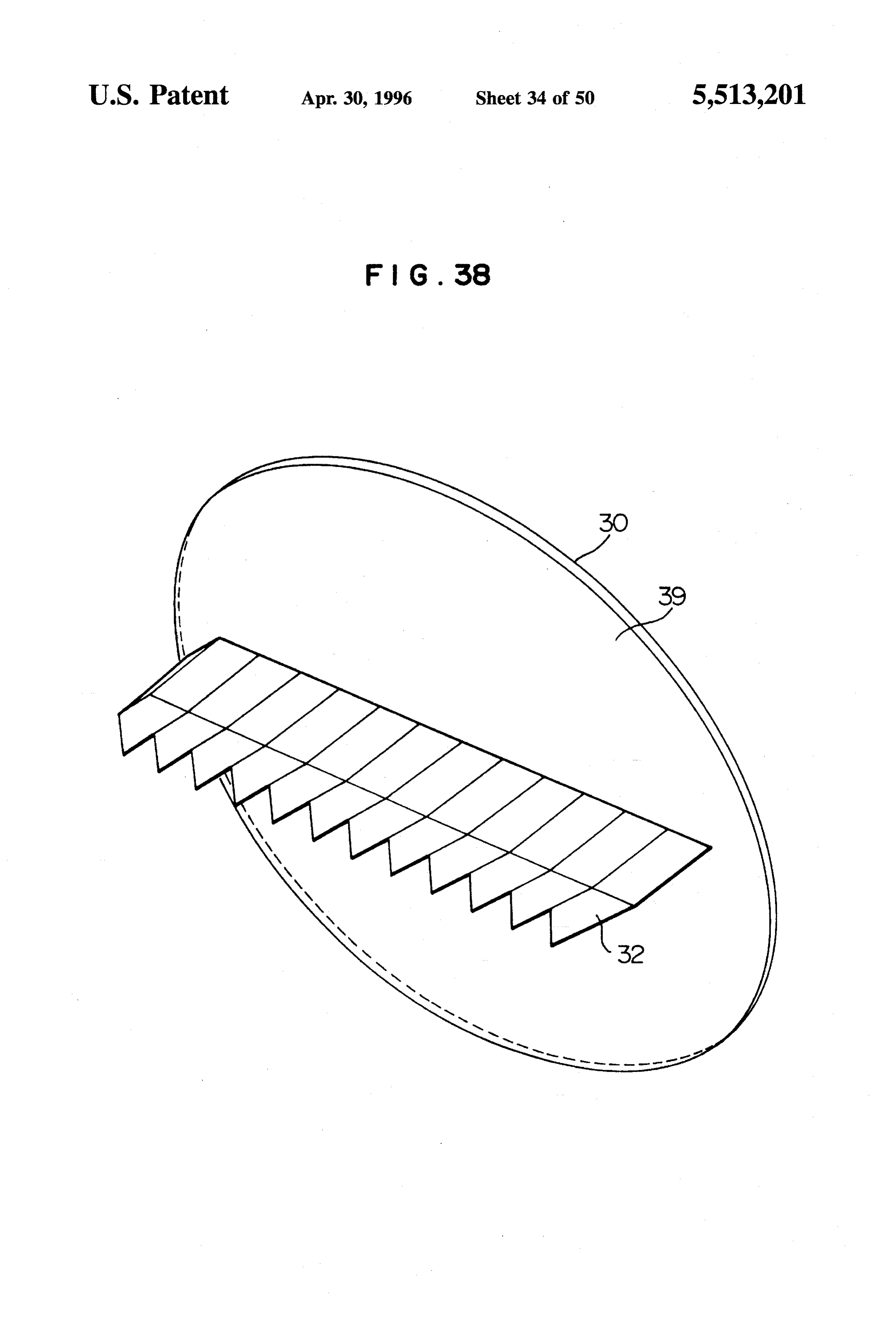
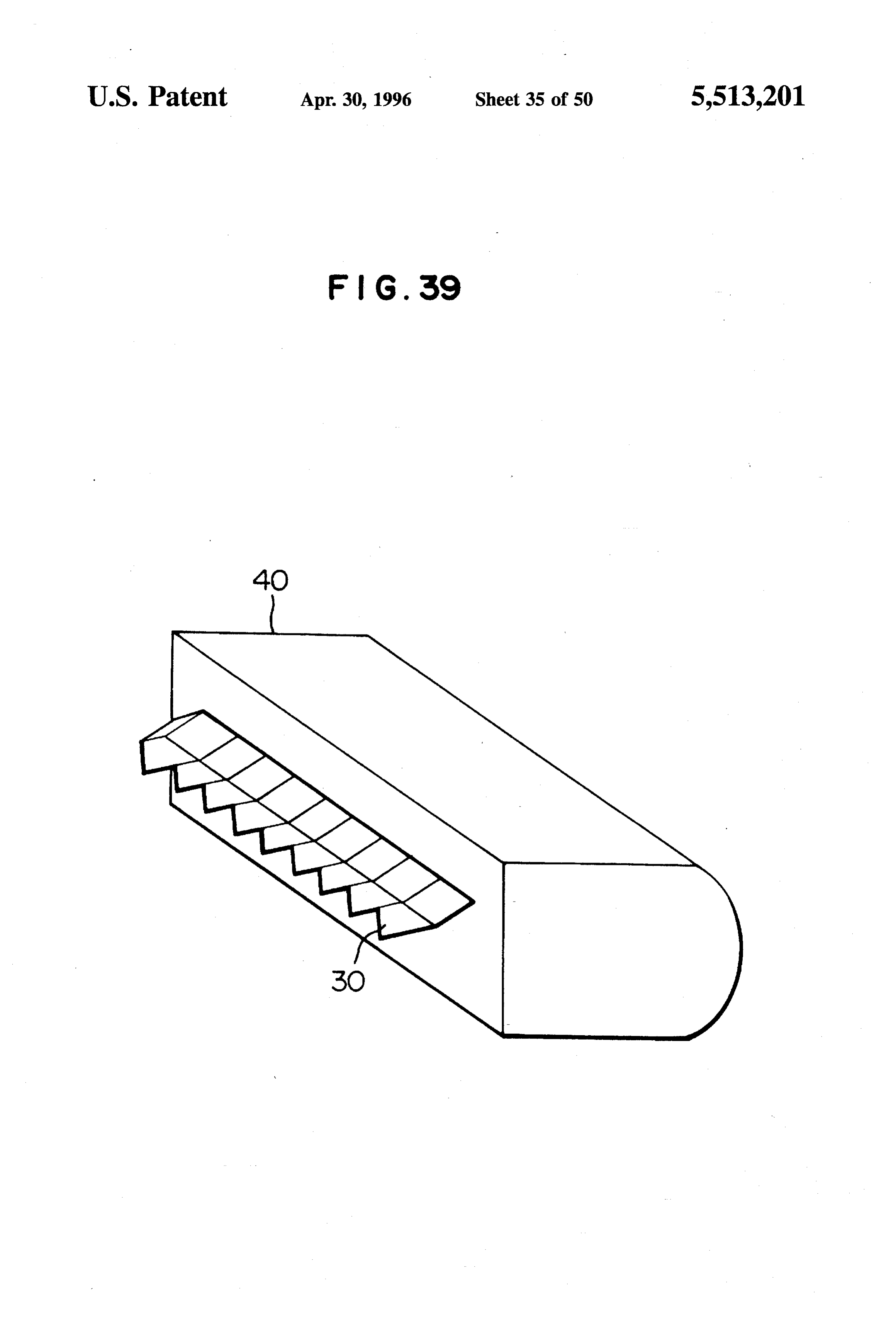
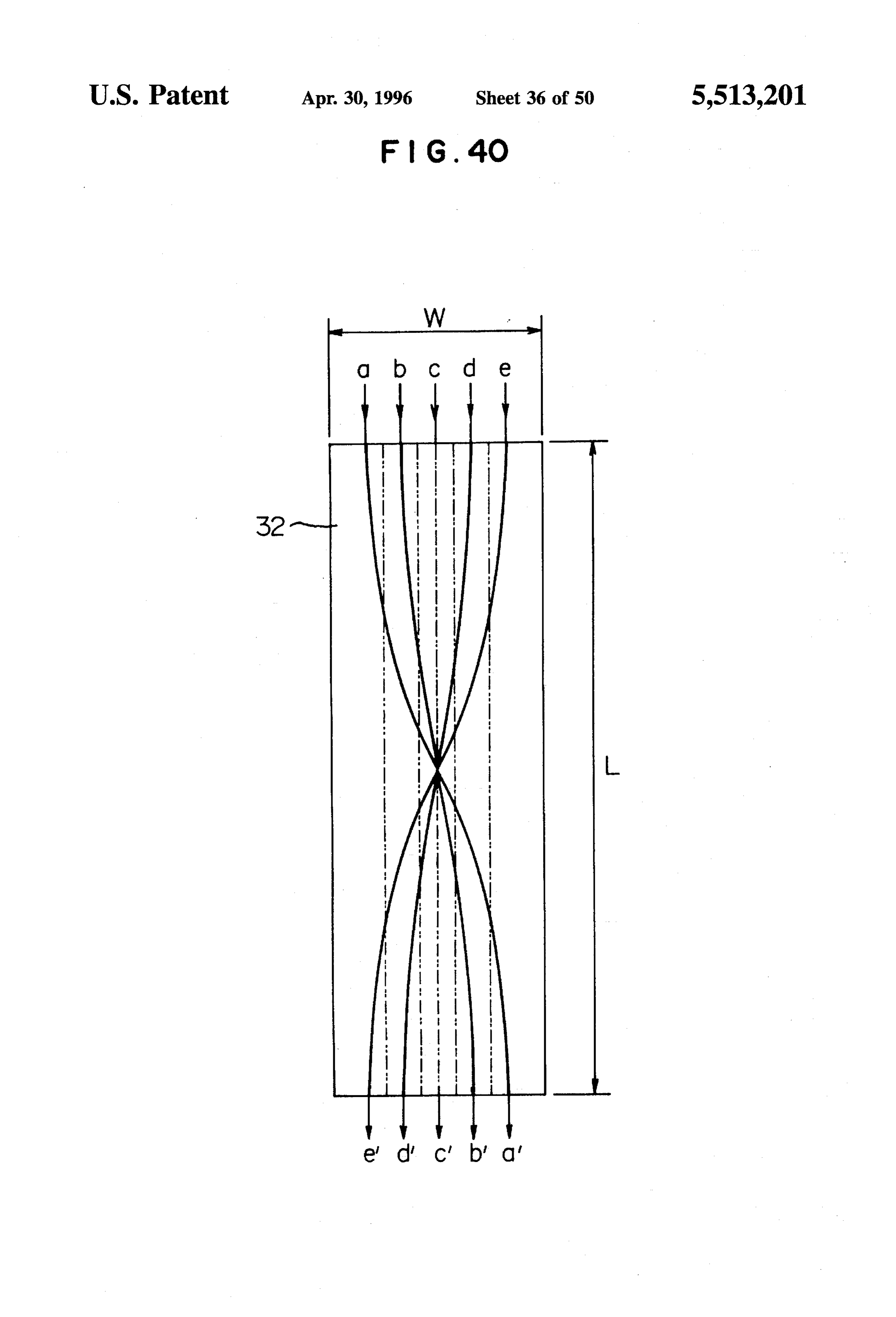
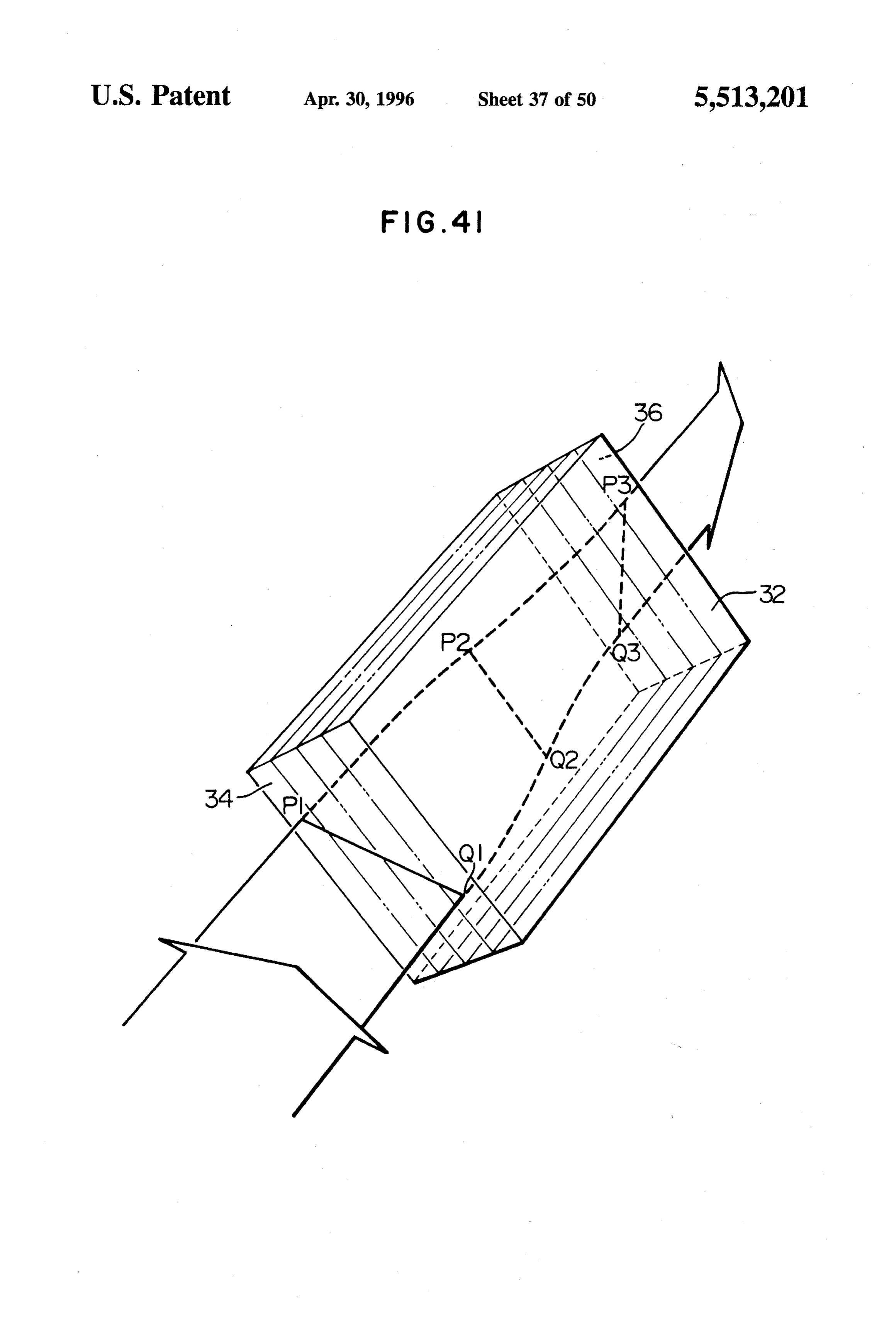
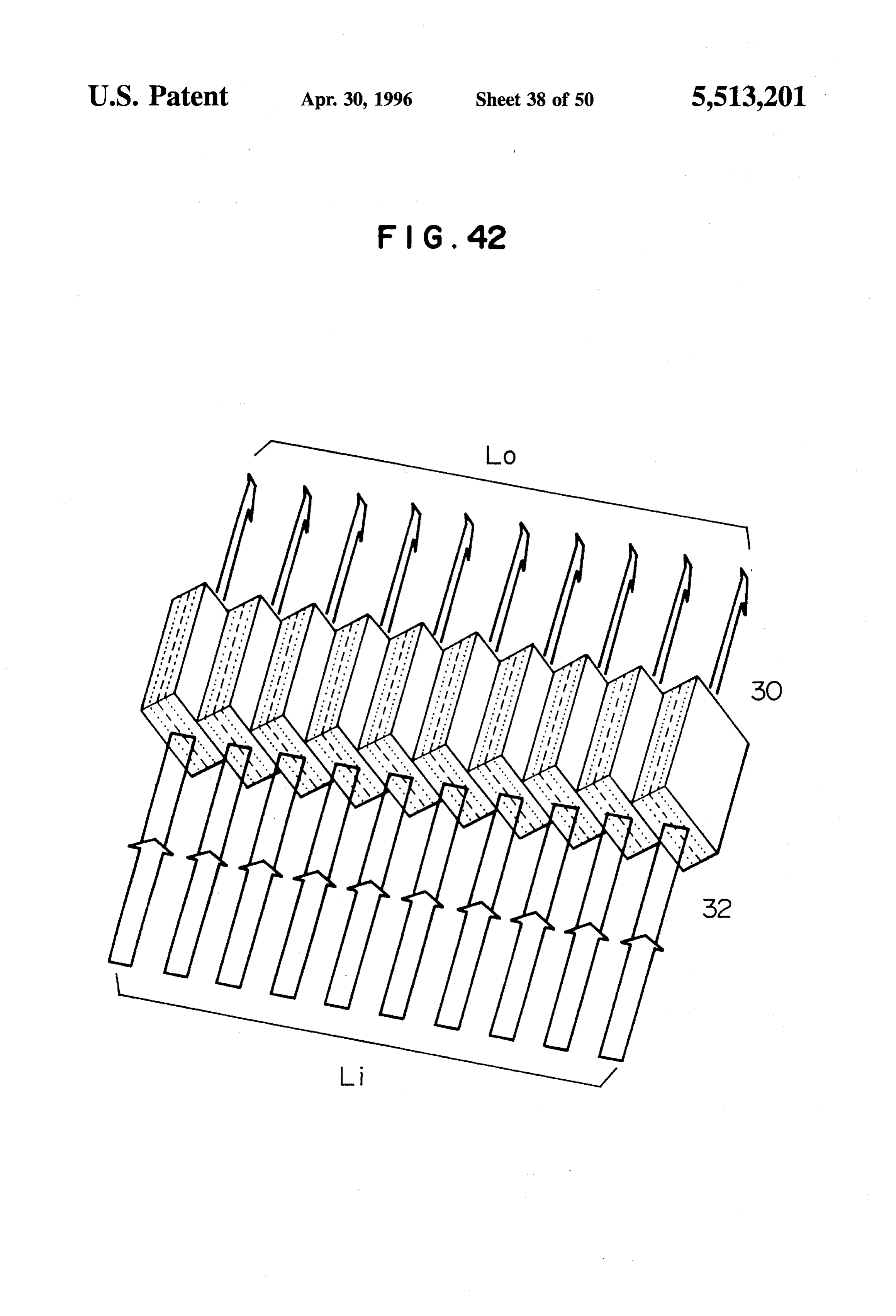
device of the present invention having the optical elements FIG. 39 is a diagram showing an optical path rotating of FIG. 15 arranged in parallel; device fitted with a cylindrical lens for collimation; FIG. 17 is a perspective view of another optical path FIG. 40 is a diagram for explaining the function of a lens rotating device of the present invention, formed by having 65 with a linearly-distributed refractive index; the optical path rotating device of FIG.16 added with a right FIG. 41 is a perspective view of an optical element using angle prism; a lens with a linearly-distributed refractive index;
Page 55
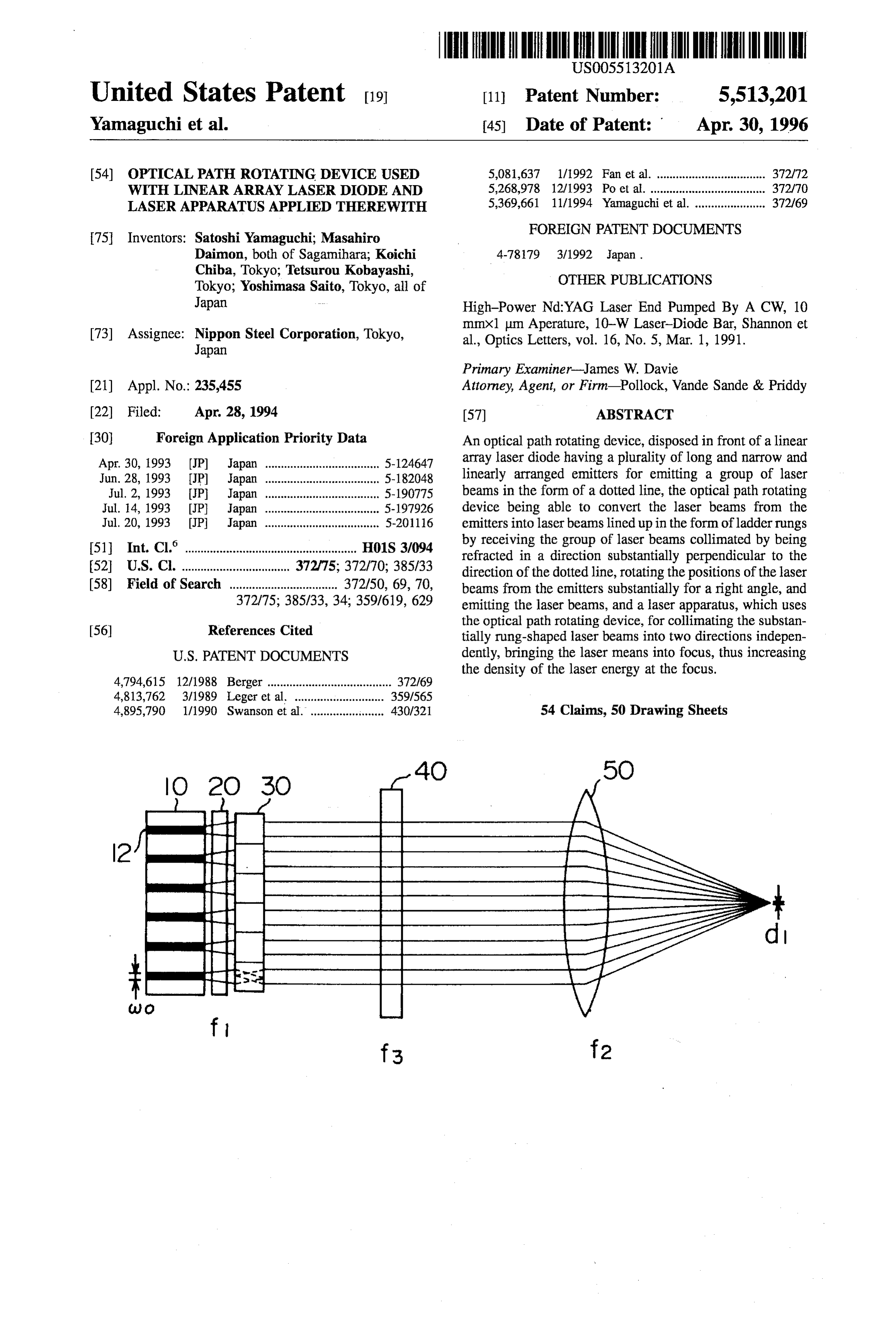
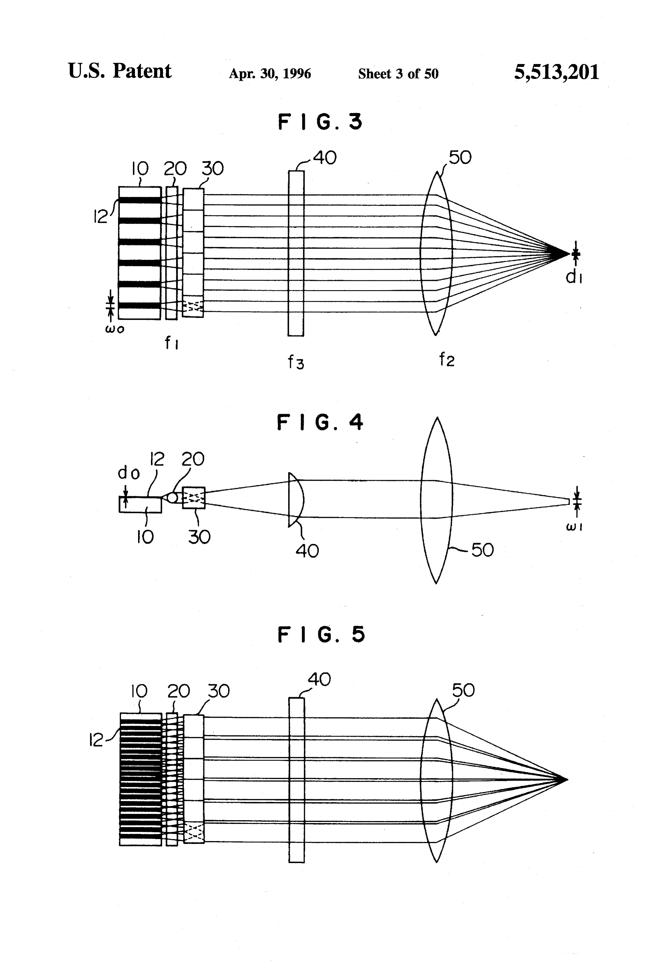
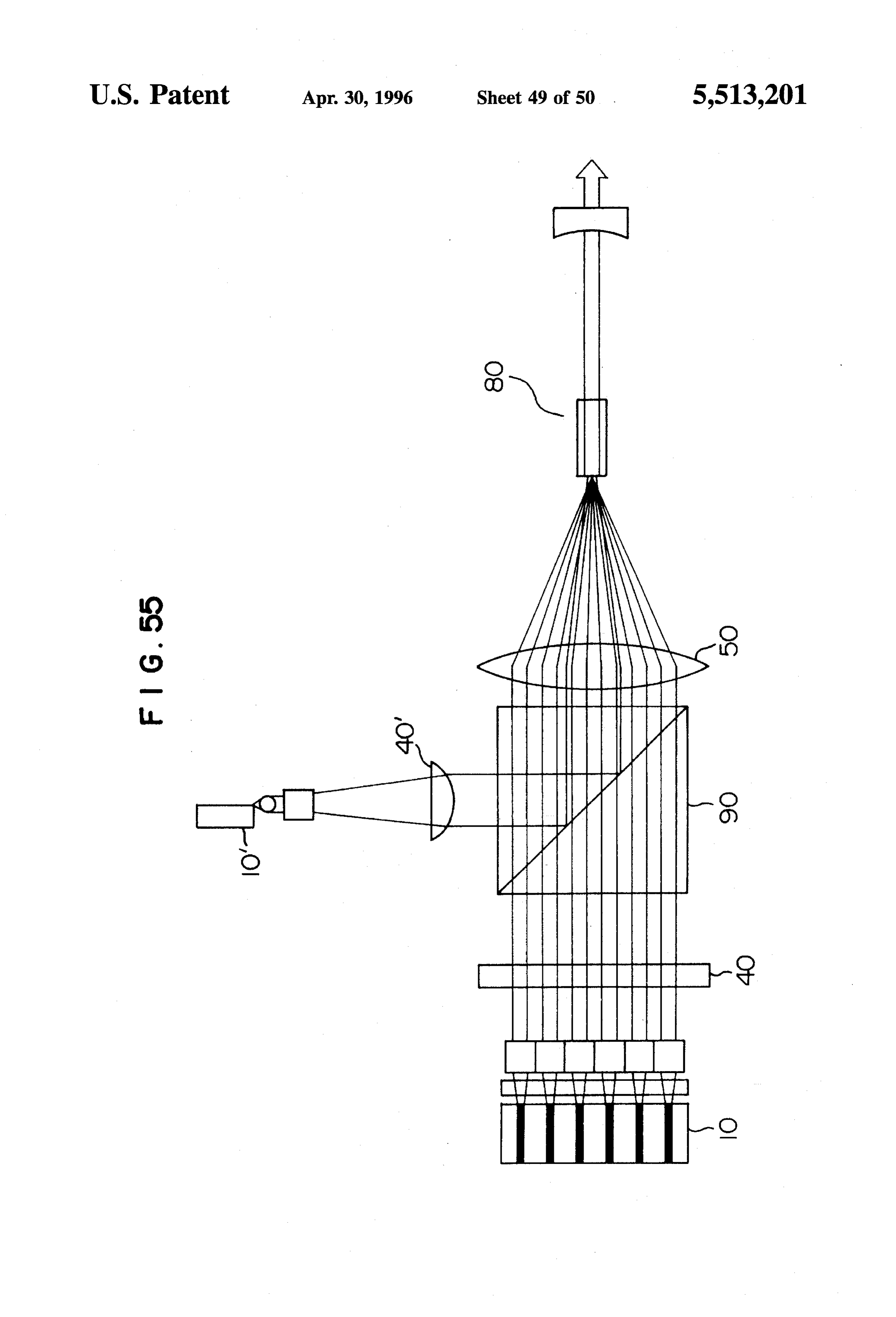
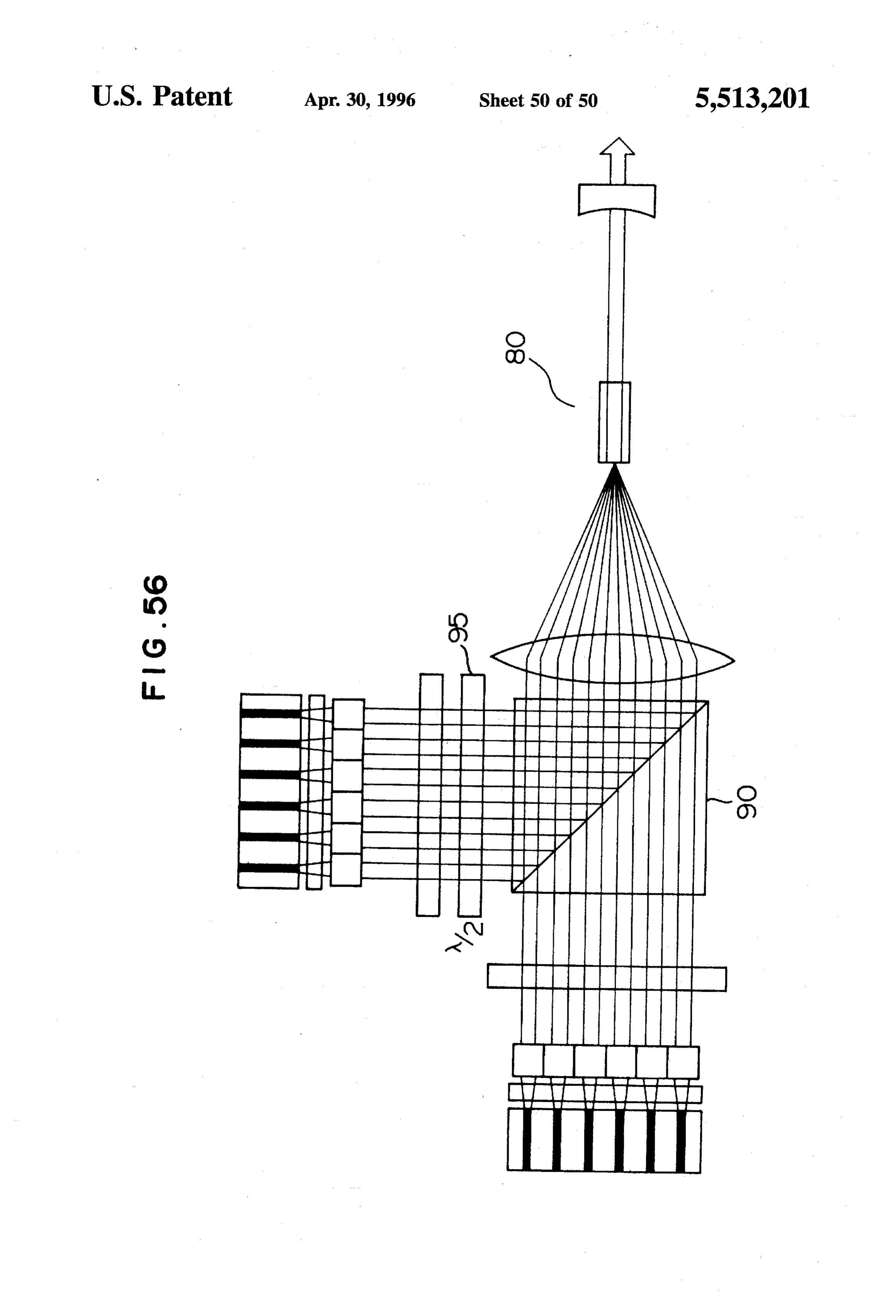
FIG. 42 is a perspective view of an optical path rotating 10, so that the radiation from the semiconductor laser is device having the optical elements of FIG. 41 arranged in shaped like a dotted line.
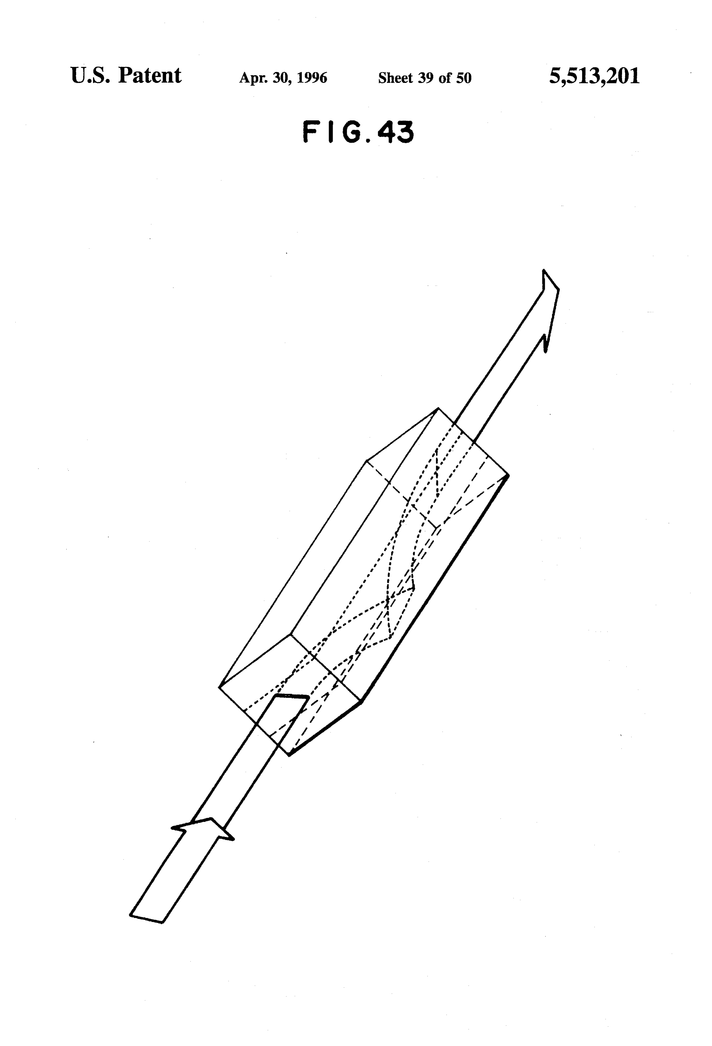
parallel; The first cylindrical lens 20 has a condensing power for FIG. 43 is a perspective view of an optical element using condensing the laser beams from the multi-stripe array another lens of a linearly-distributed refractive index; semiconductor laser 10 in the thickness direction of the FIG. 44 is a perspective view of an optical path rotating active layer stripes, and therefore the lens 20 changes the device having arranged on either side of an optical glass radiant beams as the components normal to the active layer body semi-cylindrical portions each with a concentric stripes into parallel beams. The first cylindrical lens 20, refractive index distribution; having a uniform length in its width direction, allows the O light to travel substantially straight, and therefore the diver
FIG. 45 is a perspective view of an optical path rotating gence angle of the laser beams in the width direction remains device having cylindrical lenses arranged in two parallel about 10 degrees.
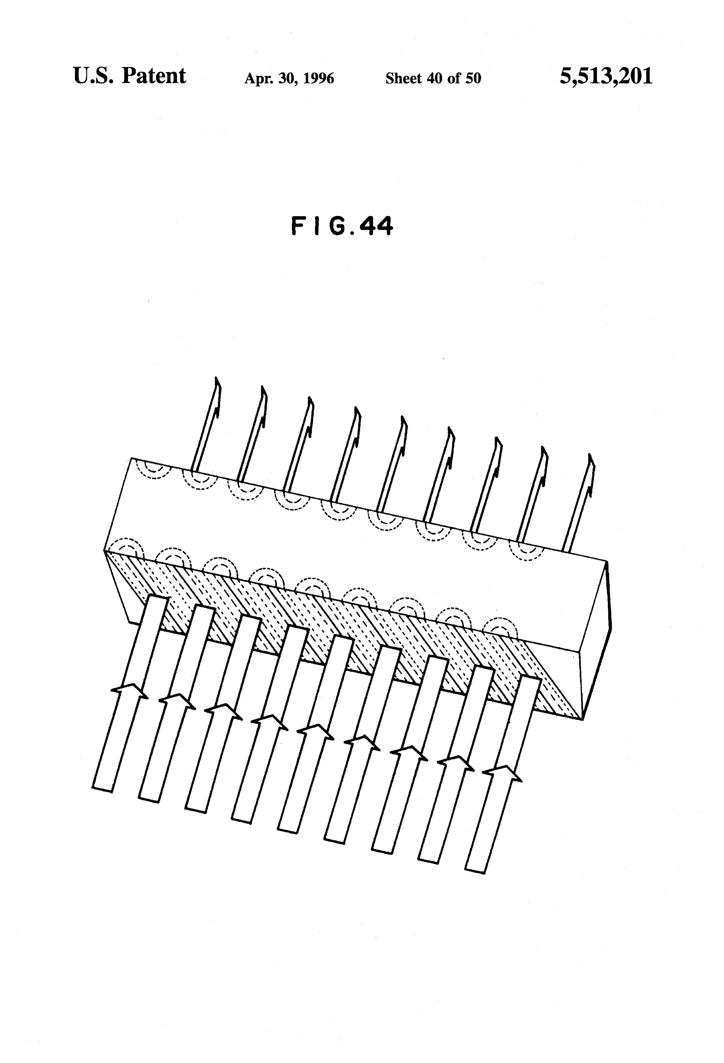
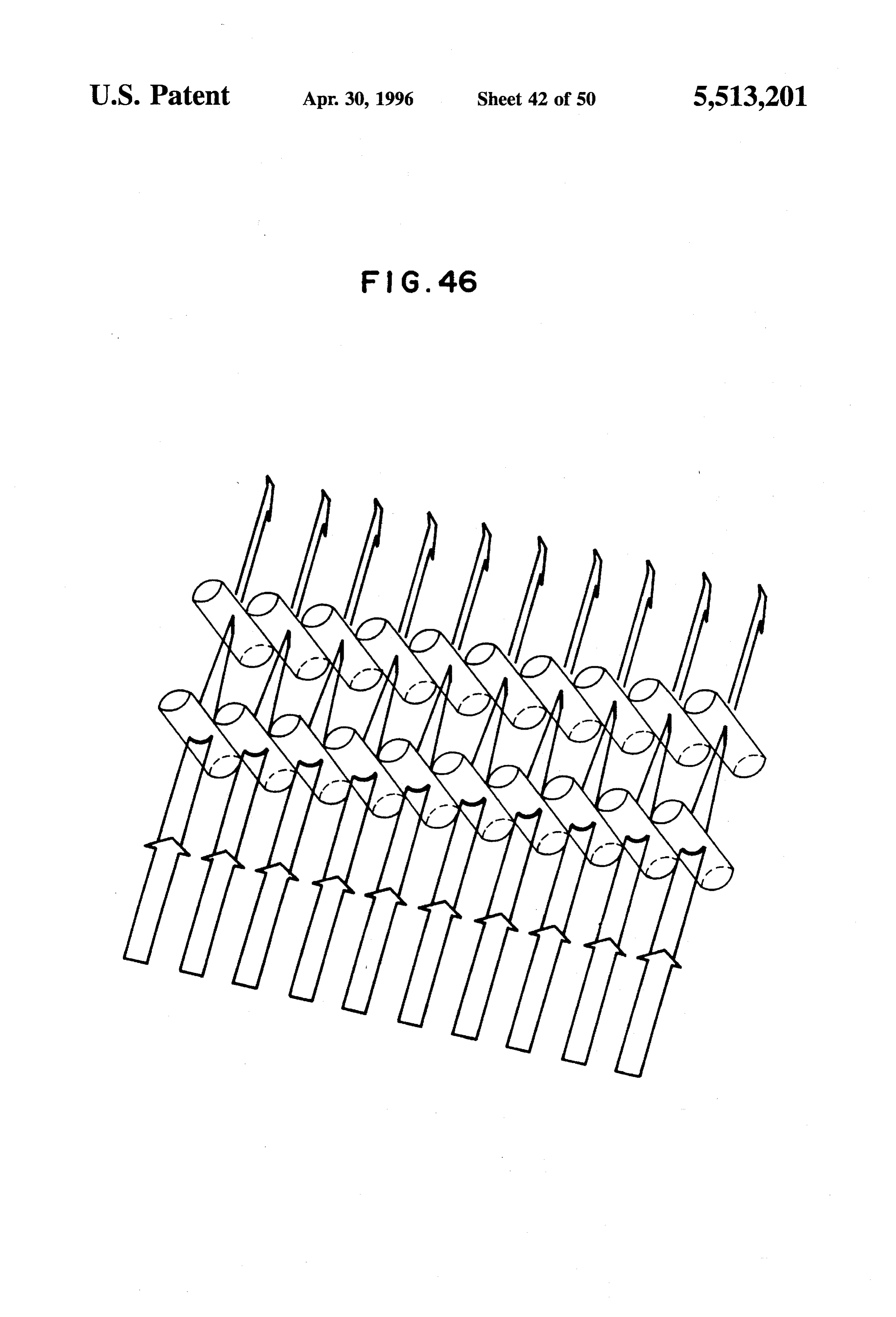
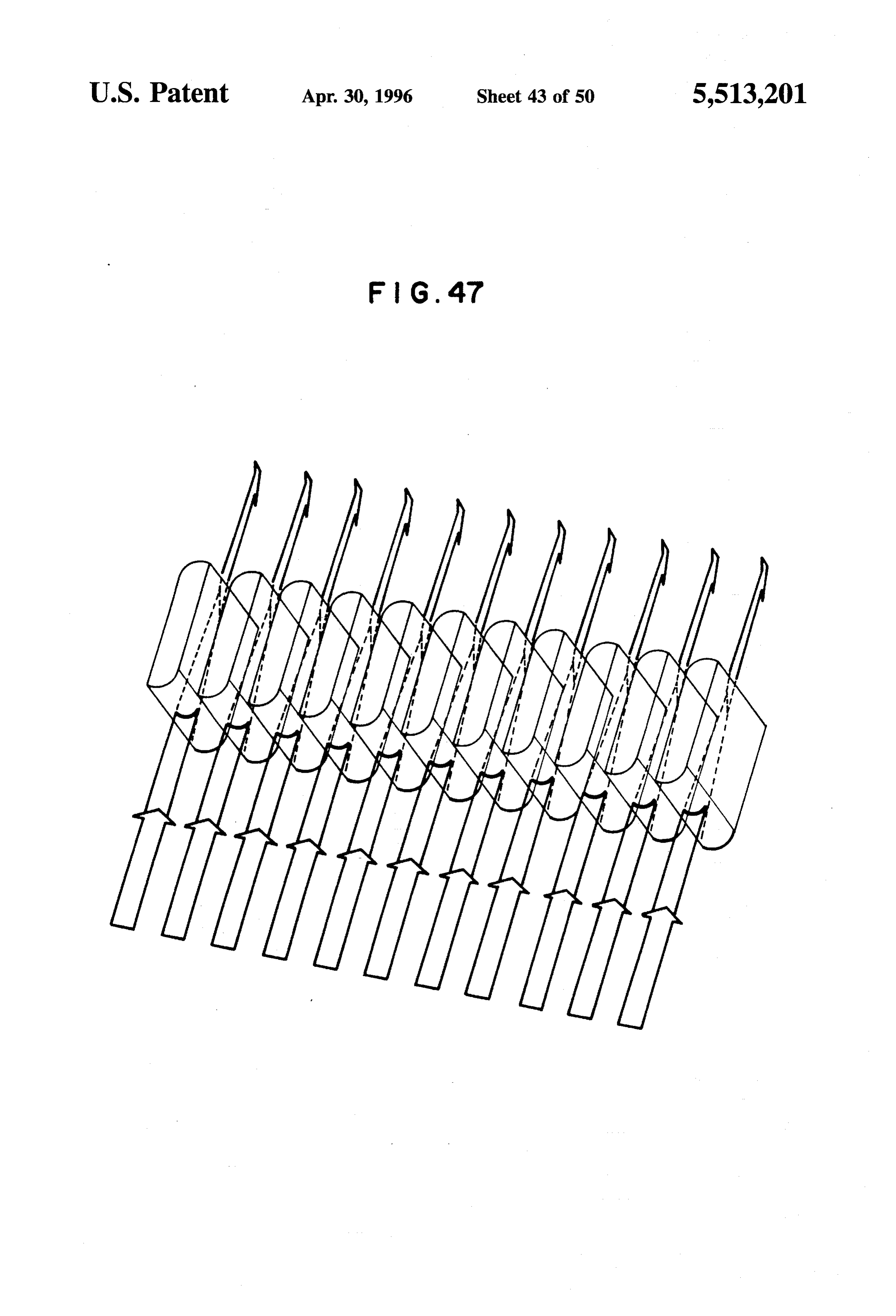
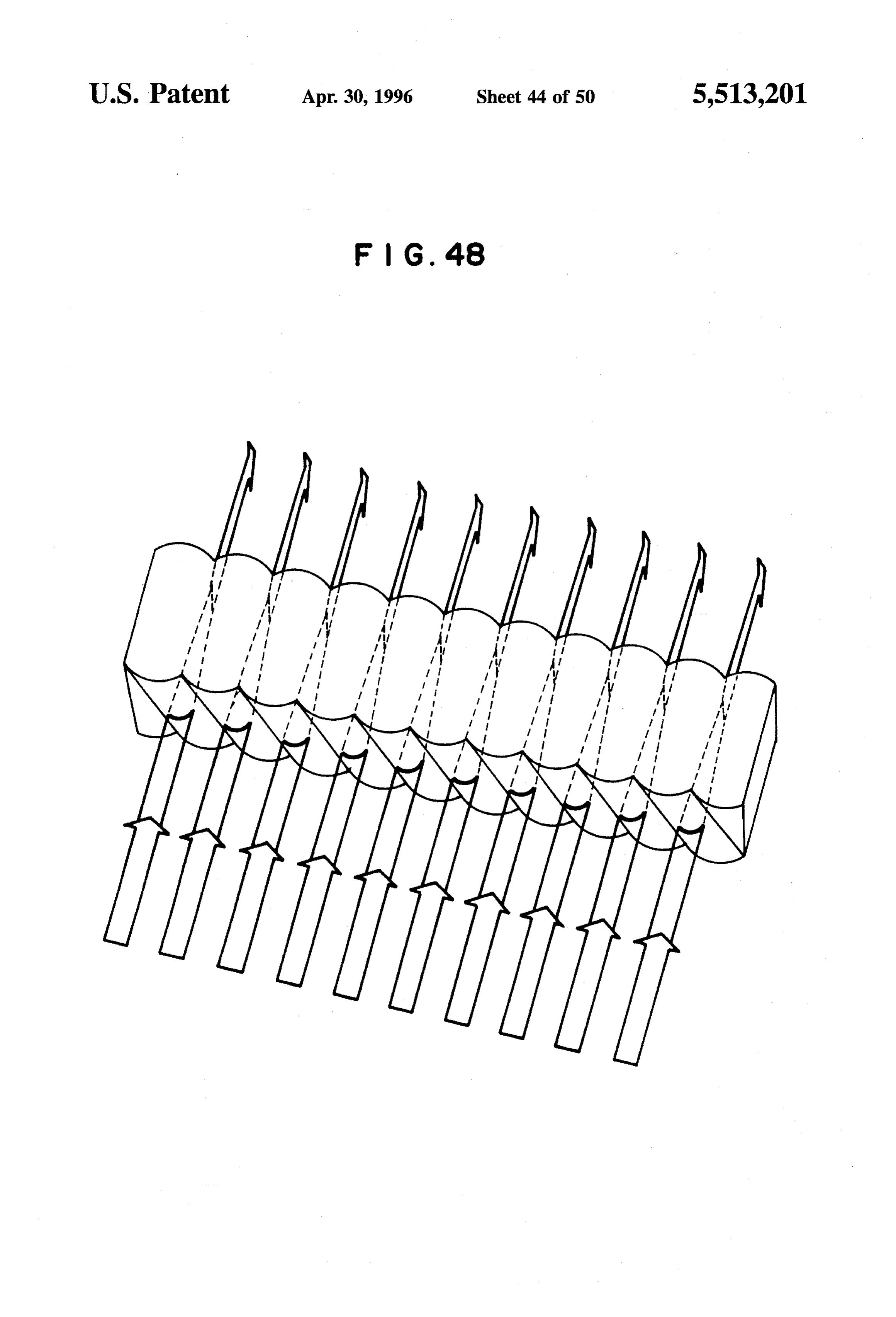
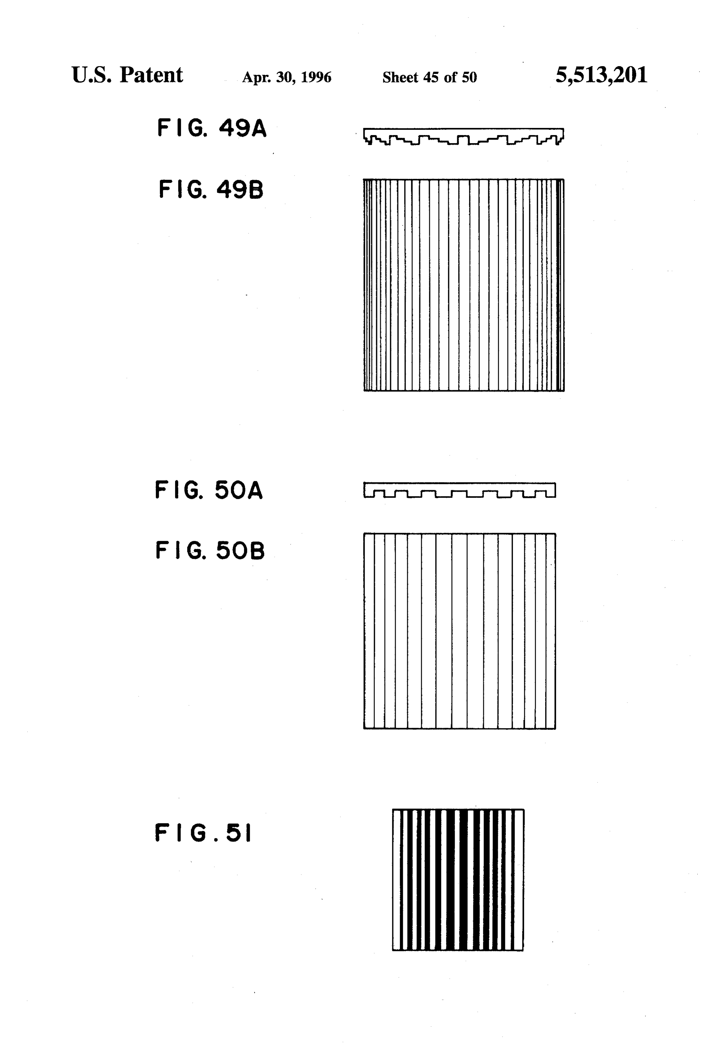
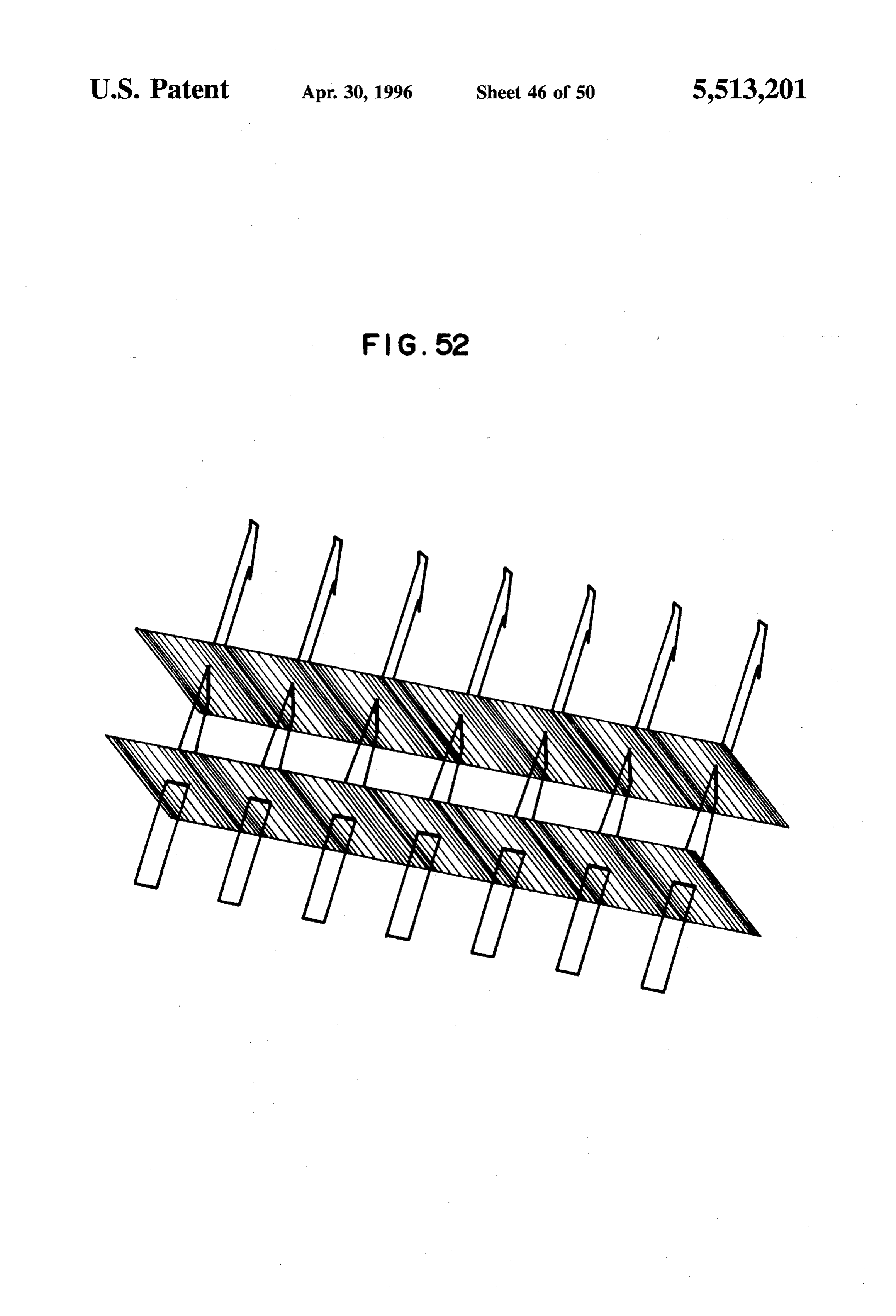
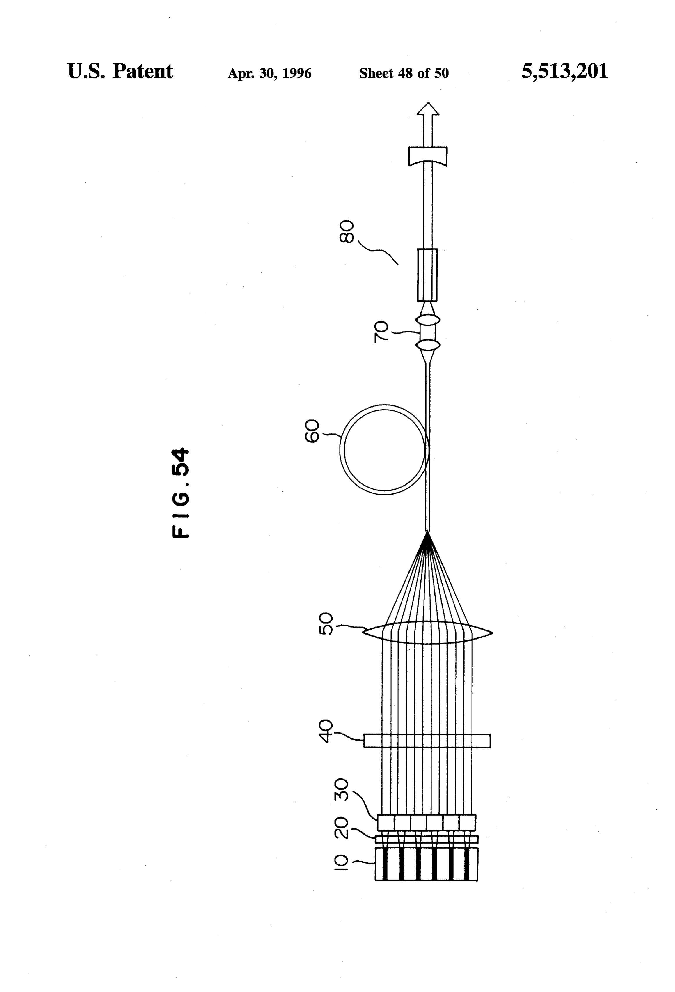
lines; An optical path rotating device 30 rotates the cross section FIG. 46 is a perspective view of an optical path rotating of the laser beams incident from the first cylindrical lens 20 device having cylindrical lenses of another type arranged in 15 by substantially 90 degrees with respect to the cross section two parallel lines; at the position of the incident light. The optical path rotating FIG. 47 is a perspective view of an optical path rotating device 30 includes optical elements on a one-to-one corre device having optical elements with cylindrical faces for spondence with the active layer stripes 12 of the multi-stripe receiving and emitting light arranged in parallel; array semiconductor laser 10, and the optical elements are FIG. 48 is a perspective view of an optical path rotating 20 arranged linearly so as to correspond to the respective active device formed from a block of optical glass; layer stripes. As they pass through the first cylindrical lens FIGS. 49A and 49B are is a diagrams for explaining an 20, the laser beams travel at a divergence angle of about ten optical element utilizing binary optics; degrees in the width direction and in parallel in the thickness FIGS. 50A and 50B are is a diagrams for explaining an 25 to direction (see FIG.3). Rotated about 90 degrees with respect optical element utilizing a laminar Fresnel Zone plate; the respective active layer stripes by the optical path rotating device 30, the laser beams are changed into parallel
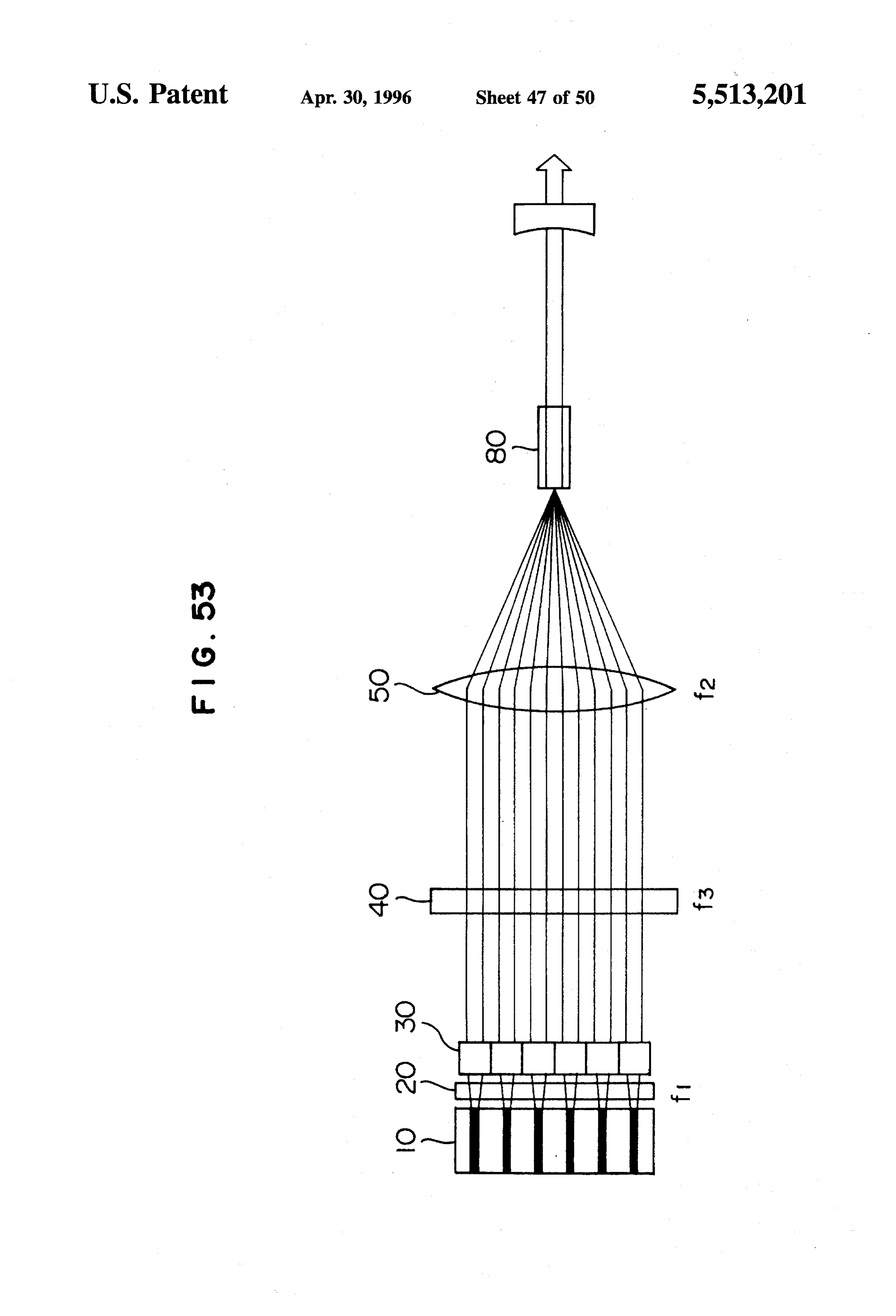
FIG. 51 is a diagram for explaining an optical element beams in the width direction but have a divergence angle of utilizing a mask type Fresnel Zone plate; about ten degrees expanding in the thickness direction (see FIG. 52 is a diagram for explaining an optical path FIG. 4). Note that the optical elements may be provided such rotating device utilizing diffraction; 30 that each optical element covers a group of multiple active FIG. 53 is a block diagram for explaining a semiconduc layer stripes.
tor-laser-pumped solid state laser apparatus; The laser beams whose optical paths have been rotated FIG. 54 is a block diagram for explaining optical fiber about 90 degrees are arranged in the same number of parallel guided semiconductor-laser-pumped solid state laser appa 35 lines as the number of the active layer stripes or the number ratus; of the groups of stripes, and therefore the radiant beams of FIG. 55 is a block diagram of a semiconductor-laser the multi-stripe array semiconductor laser 10 are substan pumped solid state laser apparatus using two linear array tially the same as those when the active layer stripes are semiconductor laser elements; and arranged in a row like ladder rungs. FIG. 56 is a block diagram of another semiconductor 40 The second cylindrical lens 40 is placed in parallel with laser-pumped solid state laser apparatus using two linear the multi-stripe array semiconductor laser 10 in the width direction of the semiconductor laser 10.
array semiconductor laser elements.
Of the laser beams which were emitted from the multi
DESCRIPTION OF THE PREFERRED stripe array semiconductor laser 10 and passed through both EMBODIMENTS 45 the first cylindrical lens 20 and the optical path rotating device 30, the light components normal to the active layer
The present invention will be described with reference to stripes become parallel beams separately for the respective the accompanying drawings. active layer stripes, and the laser beams have a divergence angle of about ten degrees, expanding in the width direction.
Embodiment 1 50 Since the laser beams are arranged in the form of ladder rungs, the whole of the laser beams from the overall length
FIG.3 is a plan view of the semiconductor laser apparatus of the emission face of the semiconductor laser has a of the present invention, and FIG. 4 is its elevation view. divergence angle of about ten degrees. The second cylindri A multi-stripe array semiconductor laser 10, which is an cal lens 40 receives the laser beams and changes them into example available on the market, has arranged in a row 55 parallel beams as viewed from above, so that the laser beams being 10-mm long 10 to 100 pieces (12 pieces for example, are now parallel beams as viewed both in the width and but six pieces are shown in the figure for simplicity's sake) thickness directions.
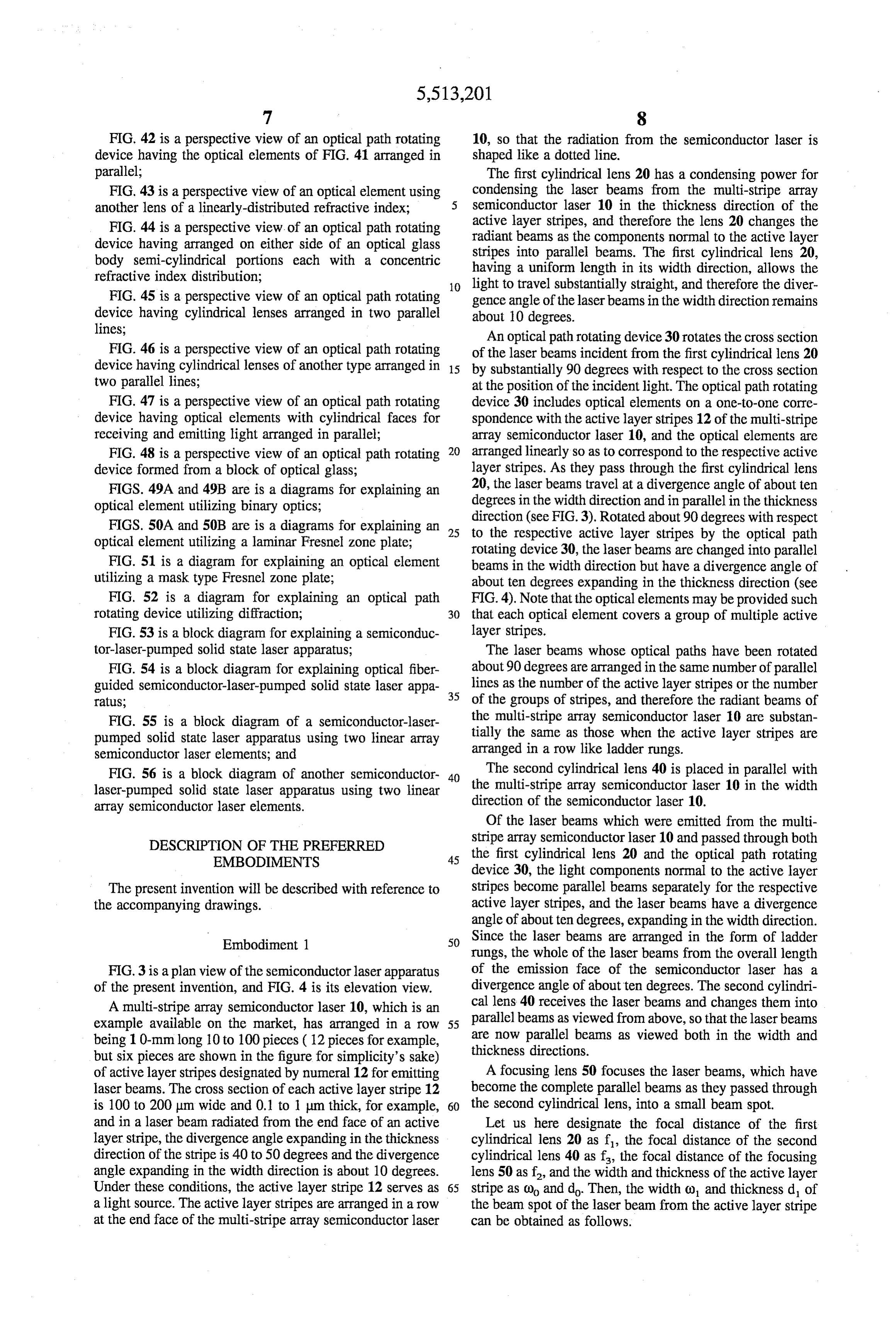
of active layer stripes designated by numeral 12 for emitting A focusing lens 50 focuses the laser beams, which have laser beams. The cross section of each active layer stripe 12 become the complete parallel beams as they passed through is 100 to 200 um wide and 0.1 to 1 um thick, for example, 60 the second cylindrical lens, into a small beam spot. and in a laser beam radiated from the end face of an active Let us here designate the focal distance of the first layer stripe, the divergence angle expanding in the thickness cylindrical lens 20 as f, the focal distance of the second direction of the stripe is 40 to 50 degrees and the divergence cylindrical lens 40 as f, the focal distance of the focusing angle expanding in the width direction is about 10 degrees. lens 50 as f, and the width and thickness of the active layer Under these conditions, the active layer stripe 12 serves as 65 Stripe as () and do. Then, the width () and thickness d of a light source. The active layer stripes are arranged in a row the beam spot of the laser beam from the active layer stripe at the end face of the multi-stripe array semiconductor laser can be obtained as follows.
Page 56
didofff stripe instead of a number of dots, and by dividing the stripe (0.1-(noff into a suitable number of subdivisions by the optical ele ments and rotating them laser diode emitting light beams are
Therefore, in order to obtain a sharp spot, the greater are substantially in the form of ladder rungs. f and f, the better. Considering that coo is 100 to 200 um FIG. 6 is a plan view of the laser apparatus according to and do is 0.1 to um, the magnitude of f is of no the present invention using an optical fiber 60, and FIG. 7 is significance compared with f. In the case where the stripe its elevation view. A light receiving end face of the optical width () is 200 um, the stripe pitch is 800 um and the fiber 60 is placed at a position of a laser light spot formed divergence angle expanding in the length-wise direction of by the laser apparatus, and the laser energy radiated by the the stripes is ten degrees, the laser beam from the adjacent 10 laser 10 is transmitted through the optical fiber 60 to the stripes overlap each other at 3.4 mm away from the stripe other end face. An easy-to-use laser apparatus can be face as they are widening in the lengthwise direction of the obtained which has the length and flexibility of the optical stripes. fiber 60 to enable the emitter portion to be easily brought Therefore, when the optical path rotating device of the into the site of use. A laser apparatus which used the linear present invention is not used, in order to utilize output 15 array laser diode 10 with an output of 10 W as the light energy with high efficiency, the first and second cylindrical source and formed a small laser light spot smaller than the lenses need to be placed at a distance of 3.4 mm or less from cross section of the core on the incident face of the optical the stripe face, and in order to collimate the laser beams, the fiber 60 with a core diameter of 400 um performed with the focal distances f and f must be 3.4 mm at the longest. efficiency of 60%.
However, if the first cylindrical lens with f of a suitable 20 value of 3.4 mm or less is placed at a distance of 3.4 mm or Embodiment 2 less away from the stripe face and the laser beams are rotated FIG. 8 is a block diagram for explaining the optical path by the optical path rotating device of the present invention, rotating device according to the present invention, and FIG. the laser beams become parallel beams in a direction in 9 is a diagram for explaining the function of the optical which the laser beams corresponding to the active layer 25 element as a component of the optical path rotating device. stripes are arranged in parallel, and they never overlap each other. Those parallel beams widen at an angle of about ten The optical path rotating device 30 is formed in a rectangular shape by connecting a suitable number of optical elements degrees in a direction parallel with FIG. 4 on the paper. To 32 in the longitudinal direction of the device as shown in change the radiant beams into parallel beams by the second cylindrical lens, it is possible to set a sufficiently large value 30 FIG.8. The length of the optical path rotating device is set for the focal distance f. In other words, f is not limited by to correspond to the emitter face of the linear array laser diode. The optical element 32 has a light receiving face 34 the maximum value of 3.4 mm, but any value can be selected for receiving a laser beam 37 perpendicularly to this receiv for f. When the same value as the focal distance of the ing face. The laser beam 37 has the direction corresponding condenser lens is selected, the beam spot width co, will be 200 um. As has been described, according to the laser 35 tolongitudinal the traverse axis of the active layer stripe parallel to the apparatus of the present invention, the width o and thick shown in FIG.direction of the optical path rotating device as 9. The optical element 32 also has an output ness d can be reduced to sufficiently small values, with the face 36 for outputting a laser beam perpendicularly from the result that a powerful laser which efficiently utilizes the output face. The output laser beam has its optical path output of the linear array laser diode can be obtained.
Therefore, the laser apparatus of the present invention can be 40 twisted about as it undergoes a process of twisting the optical path the optical axis inside the optical element. The optical used for laser processing or as a laser knife in medical treatent. path element 32 accepts the laser beam 37 emitted from the active layer stripe which is placed in repetition by 800 um
FIG. 5 is a plan view of the semiconductor laser apparatus pitches, of the present invention when a quasi-continuous wave laser for example, and having the direction corresponding to the transverse diode QCWLD or the like with a high energy density at the tion and rotates the 45 axes of the stripes in the horizontal direc light emitter is used as a linear array laser diode. The linear orientation of the cross section of the array laser diode 10 has a large number of active layer stripes accepted laser beam by substantially 90 degrees. The angle 12 provided with high density, thus forming a linear light relationship between the light receiving and outputting faces emitter with substantially no separation. The optical path may be set as one pleases, but it is most desirable in design rotating device 30 having arranged linearly an adequate 50 of the apparatus that both faces are parallel to each other and number of optical elements regardless of the size of the the direction of the optical axis of the incident light is active layer stripes or in a size corresponding to a specified maintained. When the light receiving and outputting faces are not parallel with each other, it is easy to change the number of stripes. The positions and functions of the first direction cylindrical lens 20, optical path rotating device 30, second of the optical axis by having reflected the emerging cylindrical lens 40, and focusing lens 50 are the same as 55 light at a fixed angle to the direction of incidence and direct those described with reference to FIG. 3. When alaser diode the emerging light in a direction desirable for reasons of the including active layer stripes short in width or narrow in construction of the apparatus.
pitch is used, there is a problem that if it is necessary to The optical elements 32 used in the optical path rotating install the optical elements of the optical path rotating device device 30 are placed in a one-to-one correspondence with so as to correspond one to one with the active layer stripes, 60 the active layer stripes 12 of the linear array laser diode 10 then it is difficult to manufacture the optical path rotating used in the laser apparatus which generally incorporates an device. This embodiment has been made to solve this optical path rotating device. Therefore, when a linear array problem, more specifically, the above-mentioned correspon laser diode having 12 active layer stripes arranged at 800 um dence is achieved by collecting the active layer stripes into pitches, for example, the optical path rotating device has 12 groups of a certain number of stripes. It is also possible to 65 optical elements arranged at 800 um pitches. take such a view about this embodiment as follows: the However, when active layer stripes are arranged with high emitter portion of the laser diode is looked on as a single density as in the embodiment shown in FIG. 5, by regarding
Page 57
the laser beams as a single beam emitted from a continuous line, dividing the "continuous” laser beam at suitable inter vals and turning the divided laser beams about 90 degrees, respectively, the linear array laser diode can be treated as one Since the optical axis of the incident light and the trans that has a ladder-shaped emitter section substantially having 5 versal axis direction of the laser diode perpendicularly the divided emitters with a width corresponding to the intersect each other, subdivision interval. To this end, it is only necessary to arrange in parallel a suitable number of optical elements AAp=0 (5) regardless of the number of the active layer stripes.
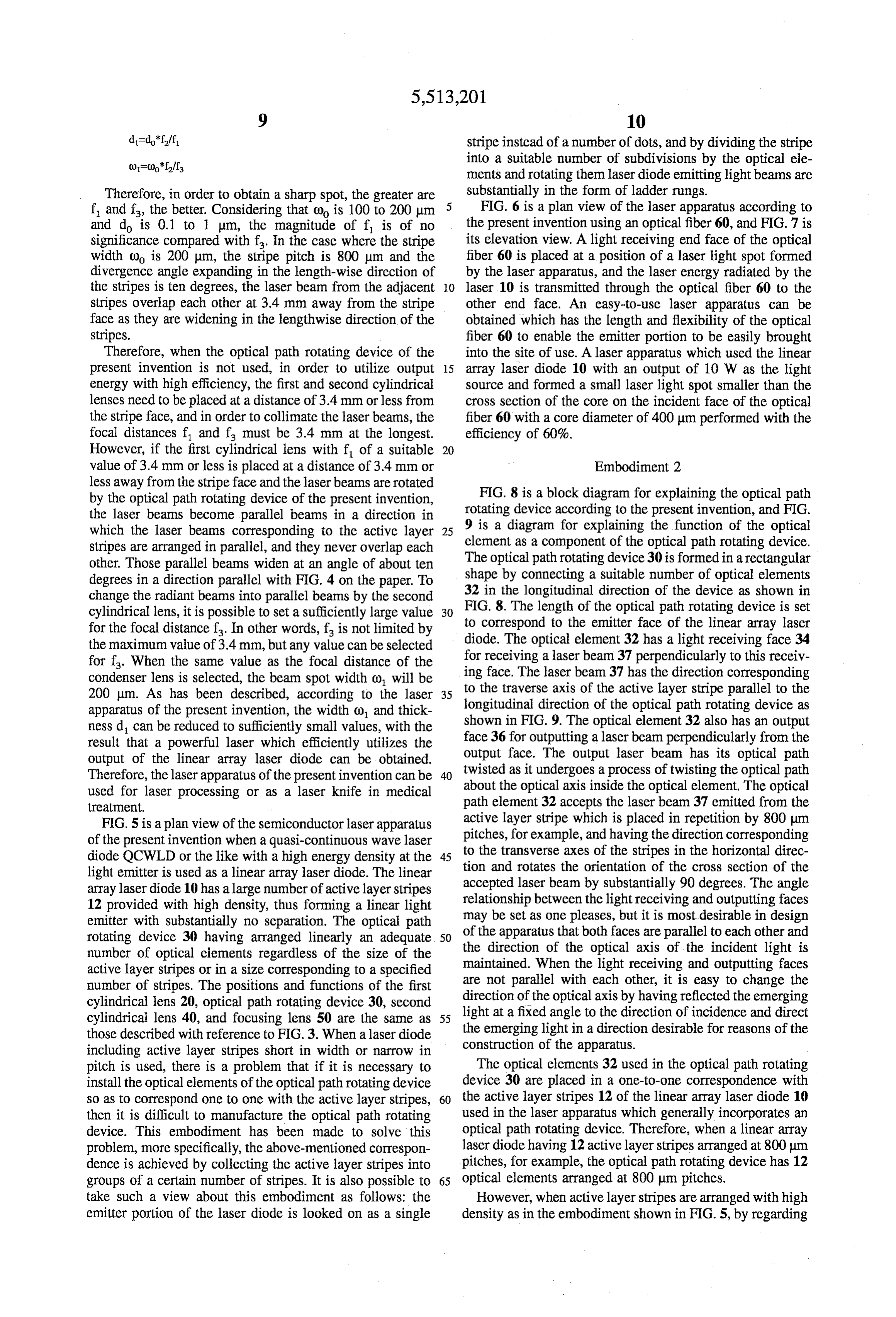
To comply with the flatness of the emitter face of the 10 If an angle between the incident light A and the emerging linear array laser diode, it is convenient in terms of the light C is designated by 0, construction of the laser apparatus to provide the incidence A-C-cos 6 (6) face 34 and the emergence face 36 of the optical path rotating device 30 as separate flat faces through the overall length of the optical path rotating device. It is possible to 15 Because the condition for the optical path rotating device divide a single incident light into two optical paths in the is that the unit vector Ap of the incident light which optical element and emit the beams from two faces of pendicularlycorresponds to the transversal axis of the laser diode per emergence. In this case, too, the faces of emergence are intersects with the unit vector Cp of the emerg provided as two separate flat faces. ing light which corresponds to the transversal axis of the The above-mentioned optical element 32 can be formed 20 laser diode, then on various principles. Ap. Cp=0 (7) FIG. 10 is a diagram for explaining the principle in a case where the optical path is changed by a combination of two From equations (1), (2) and (6), the following equation reflecting faces. In an optical element having a face of must hold.
incidence which a incident light enters perpendicularly 25 (NA)+(NA)-2(NA)(N.N.)= (1-cose)/2 (8) thereto and a face of emergence from which an emerging light emerges perpendicularly, there are provided a first From equations (3), (4) and (7), the following equation reflecting face o having a unit normal vector N and a must hold.
second reflecting face o having a unit normal vector N.
The incident light having a unit vector A of the optical axis 30 and a unit vector Ap representing the transversal axis direction of a laser diode is incident on the first reflecting The incident light falls perpendicularly to the face of face, and reflected by this face, becomes a reflected light incidence, and therefore the normal vector of the face of having a unit vector B of the optical axis and a unit vector incidence is A. On the other hand, the emerging light is Bp representing the transversal axis direction of the laser 35 emitted perpendicularly from the face of emergence, and diode. Subsequently, the reflected light is incident on the therefore, the normal vector of the normal line of the face of second reflecting face, and further reflected by this face, emergence is C.
becomes an emerging light having a unit vector C of the Therefore, the relation among the incidence face, emer optical axis and a unit vector Cp representing a transversal gence face, two reflecting faces of the optical path rotating device of the present invention, and the incident light is axis direction of the laser diode and is output from the 40 regulated optical element. By setting the angles of the two reflecting by three equations (5), (8) and (9). faces so that a specified relation is established between them, If the optical path rotating device is formed by a space the incident light is reflected twice by the two reflecting defined by two reflecting faces, the incidence face and the faces in order to change the direction of the optical axis by emergence face are mere imaginary faces without substance. an angle 0, and at the same time, by turning the direction of 45 In an optical path rotating device formed by using a the laser beam corresponding to the length of the laser diode combination of three or more reflecting faces, because the about the optical axis, so that the orientation of the cross reflecting faces have a great degree of freedom, it is difficult section of the incident light is eventually turned about 90 to express the relation among the items by a relatively degrees as compared with that when the light fell on the face simple relational expressions as shown above. of incidence. For example, when three reflecting faces are provided,
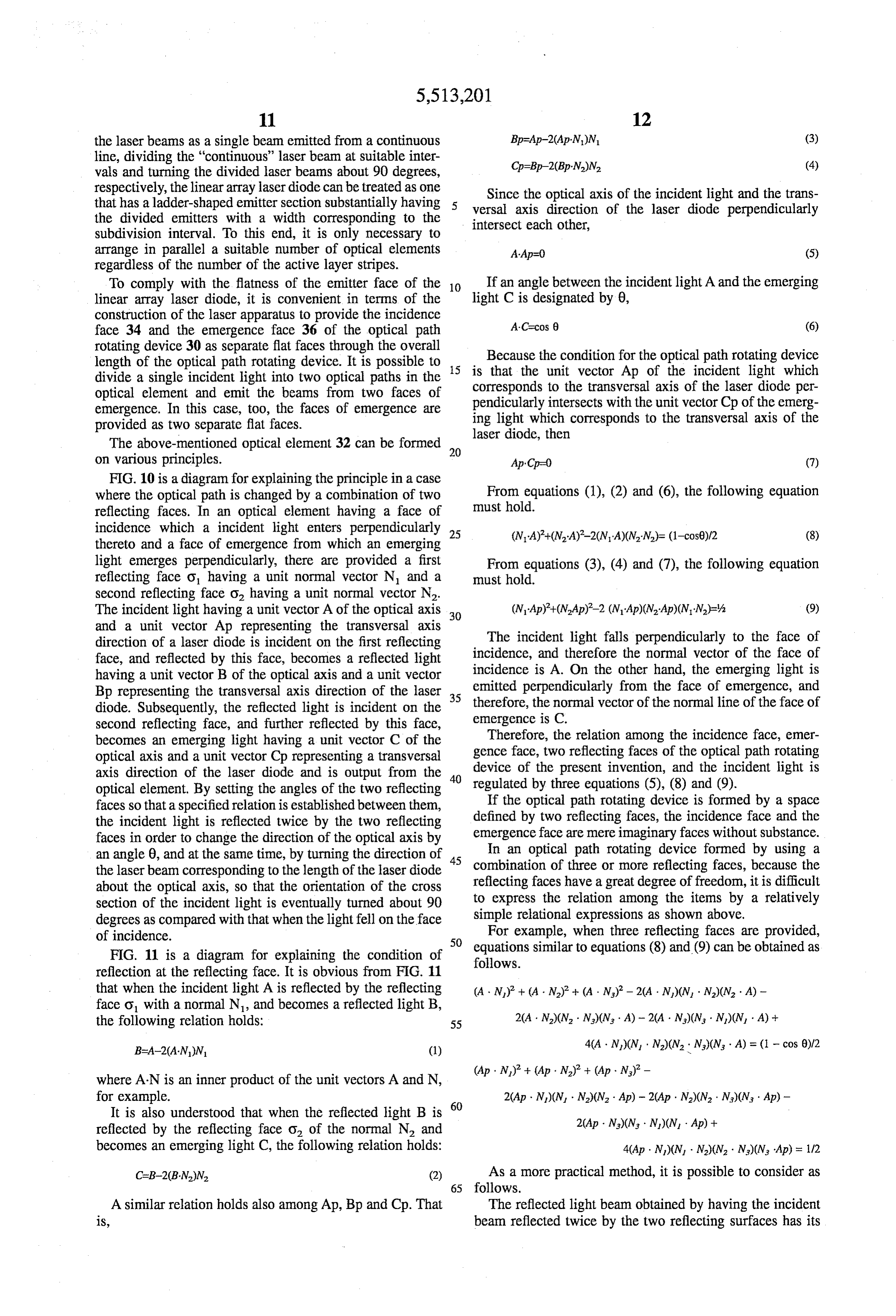
FIG. 11 is a diagram for explaining the condition of follows. similar to equations (8) and (9) can be obtained as equations reflection at the reflecting face. It is obvious from FIG. 11 that when the incident light A is reflected by the reflecting (A. N.) + (A. N.) + (A - N)-2(A. N.)(N, N2)(N - A) - face o with a normal N, and becomes a reflected light B, the following relation holds: 55 20A N) (N - N)(N - A) - 20A N) (N - N)(N - A) + B=A-2(AN)N (1) 4(A. N.)(N, N)(N. N.)(N, A) = (1-cos 0)12
where AN is an inner product of the unit vectors A and N, for example. 20Ap N)(N - N2)(N2 - Ap) - 20Ap N2)(N2 N)(N - Ap) - It is also understood that when the reflected light B is 60 20Ap N)(N - N)(N - Ap) + reflected by the reflecting face O of the normal N and becomes an emerging light C, the following relation holds: 4(Ap N)(N - N2)(N - N)(N Ap) = 1/2 C-B-2(BN)N (2) As a more practical method, it is possible to consider as 65 follows.
A similar relation holds also among Ap, Bp and Cp. That The reflected light beam obtained by having the incident is, beam reflected twice by the two reflecting surfaces has its
Page 58
optical axis different by angle 0 from that of the incident The shape of the triangular prism will be described in beam according to equation (8). Therefore, by setting a third detail. Triangles ABC and CDA are isosceles right triangles, reflecting face in a suitable direction determined by the the sides AB, AC and CD are equal in length, and an angle relation with this angle 0, the above-mentioned reflected BAC and an angle DCA are right angles. A triangle ABD and beam can be made to emerge in the same direction as the atriangle CDB are right angled triangles having a rightangle incident beam by having it reflected by the third reflecting BAD and a right angle DCB, respectively. A face ABC and face. At this time, the positions of the reflecting faces are a face CDA intersect at right angles to each other, and the arranged such that the position of the emerging beam which angle formed by the face ABC and the face ABD and the corresponds to the position of the laser beam emitting active angle formed by the face CDA and the face CDB are 45 layer stripes is to be rotated 90 degrees with respect to the 10 degrees. The face on which the light is incident is the face incident beam. The optical path rotating device, including a ABC, the face of emergence is the face CDA. As shown in plurality of optical elements as mentioned above, can FIG. 8, the light beam which is incident on the face ABC is achieve the object of the present invention as if the active reflected totally on the face ABD and then on the face CDB, layer stripes of the linear array laser diode are substantially and emerges from the face CDA. If the light beam emitted distributed in the form of ladder rungs. Thus, a typical 15 from the linear light source and is incident on the face ABC optical path rotating device constructed by combining three is designated as a line segment O.B., the line segment of reflecting faces can be obtained. is reflected totally at the line segment of in the face ABD The optical path rotating device can be constructed by and at the line segment of in the face CDB, and emerges using prisms. In this case, the above-mentioned reflecting as the line segment oap in the face CDA. faces correspond to the internal reflecting faces of the 20 In a multi-stripe array semiconductor laser having active prisms. The simplest type of an optical path rotating device layer stripes arranged linearly, generally 10 to 100 stripes using a prism is one that uses an optical element in the form about 100 to 200 um wide are arranged at fixed pitches in a of a tetrahedron. FIG. 12 is a perspective view showing the flat section about 1 cm wide. Therefore, this semiconductor simplest optical element shaped as a tetrahedron prism laser serves as a light source in a dotted line emitting 10 to having two reflecting faces. 25 100 laser beams. Since each stripe-shaped light beam is The tetrahedron prism of FIG. 12 is expressed by solid emitted from a flat light source, the beam divergence angle lines in a cube ABECDEFG. In other words, the optical is about 40 to 50 degrees large for the vertical light com element is a tetrahedron prism defined by a plane of inci ponent with respect to the active layer, and about 10 degrees dence ABC, a plane of emergence ACD, a first reflecting small for the horizontal light component. The width of each plane ABD, and a second reflecting plane BCD. The plane 30 light source is as small as 0.1 to 1 um for the vertical of incidence ABC is a part of the front face ABEC of the component, and as large as 100 to 200 um for the horizontal cube, and the normal is arranged so as to be in parallel with component. As a result, when the incident beams from the the optical axis of the incident beam, that is, so as to intersect semiconductor laser are condensed and converged by using perpendicularly to the incident beam. The first reflecting lenses, the vertical components can be easily converge, but plane ABD is formed by a part of a plane ABGD bisecting 35 it is difficult to converge the horizontal components into a the cube, and is vertical and intersects obliquely at 45 tiny spot because the total width of the light sources is large. degrees to the optical axis of the incident beam. The second Therefore, a possible solution for the above-mentioned reflecting plane BCD is formed by a part of another plane difficulty is to use micro lenses arranged on a one-to-one BCDF bisecting the cube, and is inclined at 45 degrees to correspondence with the stripes to condense and collimate horizontal, and is parallel with the optical axis of the 40 the beams and then converge the beams with a lens. The incident beam. The plane of emergence ACD is a part of the diameter of the converged beam spot is a spot diameter top face ACDE of the cube. obtained by multiplying the width of the stripes by a The incident beam is a laser beam emitted from an active magnification determined by a ratio between the distance layer stripe of the linear array laser diode, and its horizontal from the micro lenses to the beam spot and the distance from direction corresponds to the active layer stripe. The incident 45 the stripes to the micro lenses.
beam falls perpendicularly to the plane of incidence ABC, For this reason, it may be better to arrange the micro substantially all radiated energy passes through the plane of lenses as far away from the stripes as possible, but this is incidence, and then the beam enters the first reflecting plane difficult in view of the wide divergence angle of the vertical ABD. The first reflecting plane is vertical, but degrees components of the stripe beams. A possible solution is to use inclined to the incident beam, and therefore while the optical 50 separate lenses to converge the vertical and horizontal axis of the incident beam is kept horizontal, the incident components. To be more specific, a lens for converging the beam travels in parallel with the face of incidence of the vertical components is placed at a close distance from the optical element, and enters the second reflecting plane BCD. stripes and a lens for converging the horizontal components The second reflecting plane is inclined at 45 degrees to at a remote position. However, when the divergence angle horizontal, and therefore the incident beam is reflected on 55 for the horizontal components is 10 degrees, the adjacent the second reflecting plane and advances vertically upwards. stripe beams overlap when the lens is positioned beyond a The reflected beam from the second reflecting plane is certain distance, so that the distance at which the lens is set incident perpendicularly to the plane of emergence ACD, remotely is limited. In order to converge the beams at a and therefore without changing its direction, advances ver position remote from the active layer stripes, it is necessary tically upwards. 60 to take some measures to prevent the stripe beams from At this time, the direction of the incident beam corre overlapping one another.
sponding to the active layer stripe changes at the first To prevent the adjacent stripe beams from overlapping reflecting plane to the direction opposite to the optical axis, each other, the positions of the stripe beams are changed by but both directions lie in the same horizontal plane. When using prisms as if the active layer stripes arranged in a dotted the reflected beam is reflected on the second reflecting plane, 65 line were turned 90 degrees respectively and arranged in a its direction corresponding to the active layer stripe changes ladder form. More specifically, prisms as shown in FIG. 12 90 degrees, and exists in the vertical plane. are arranged on a one-to-one correspondence with the

Page 59
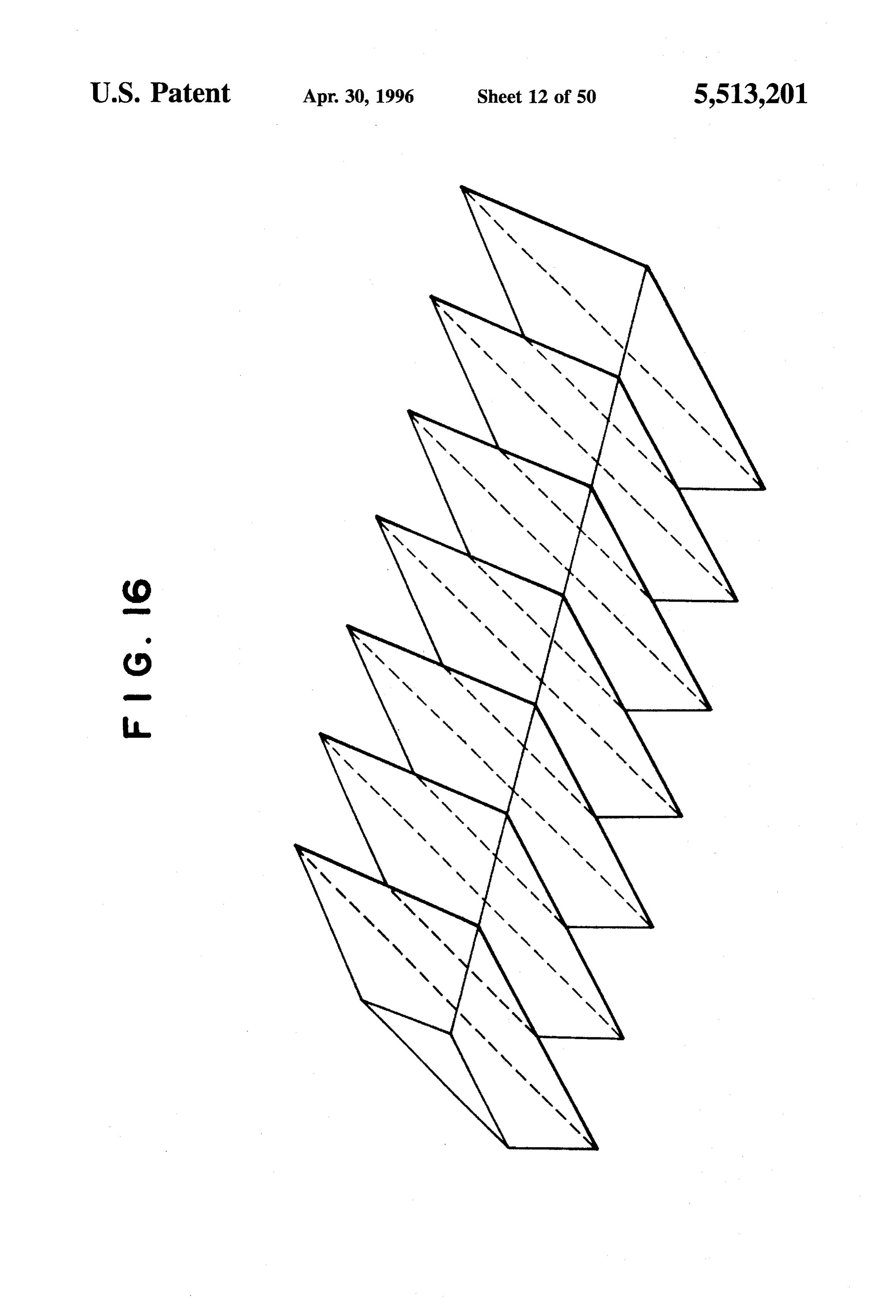
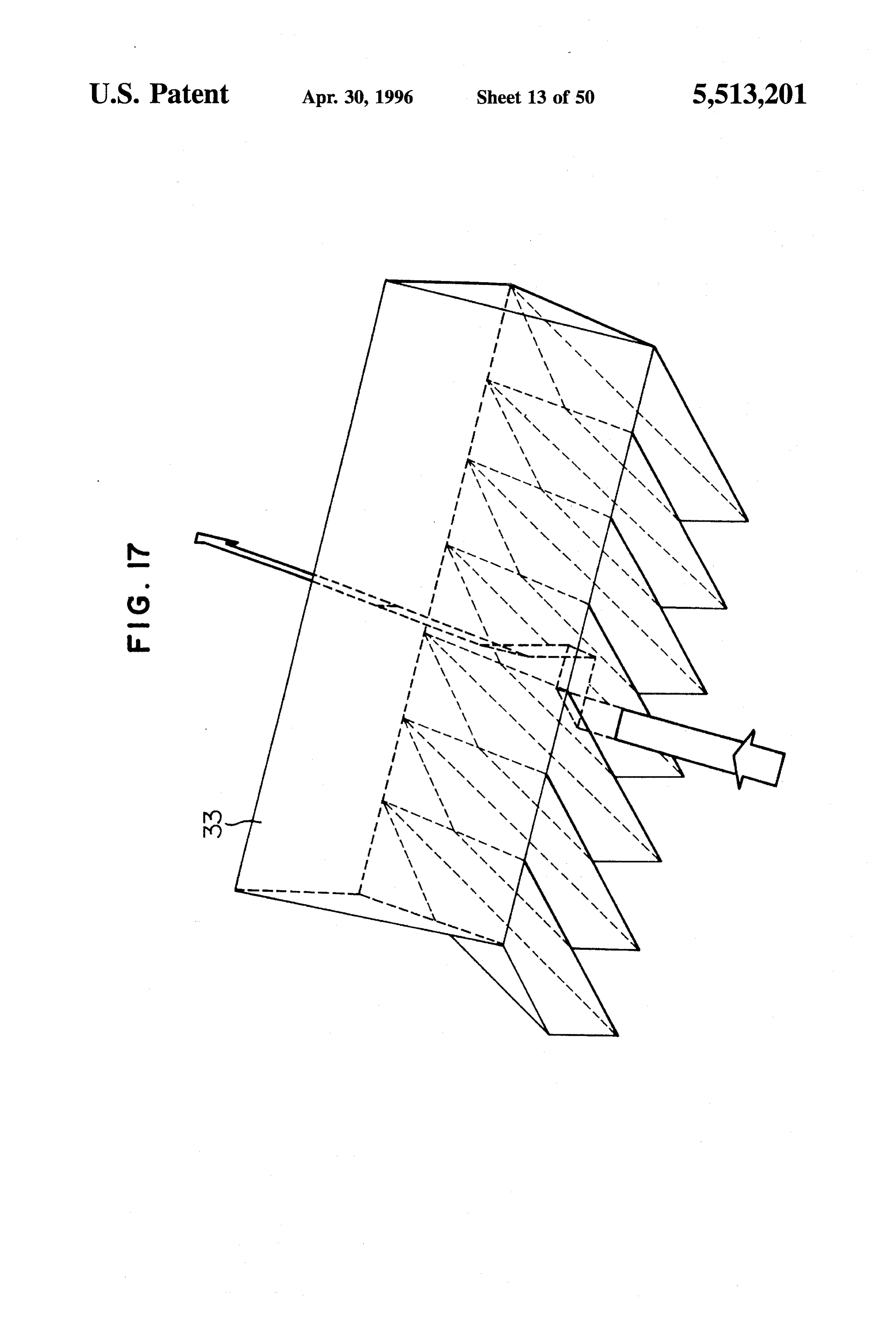
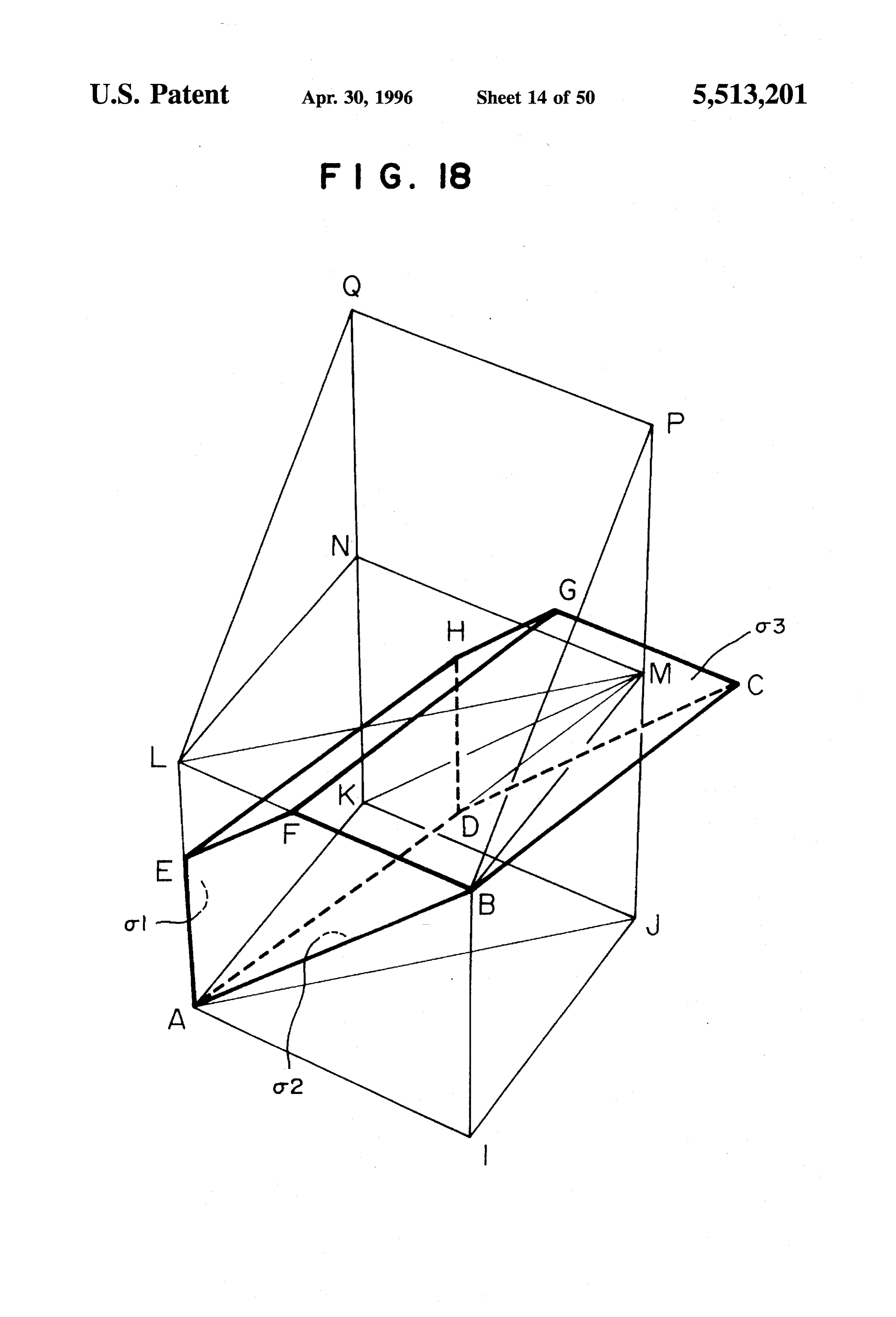
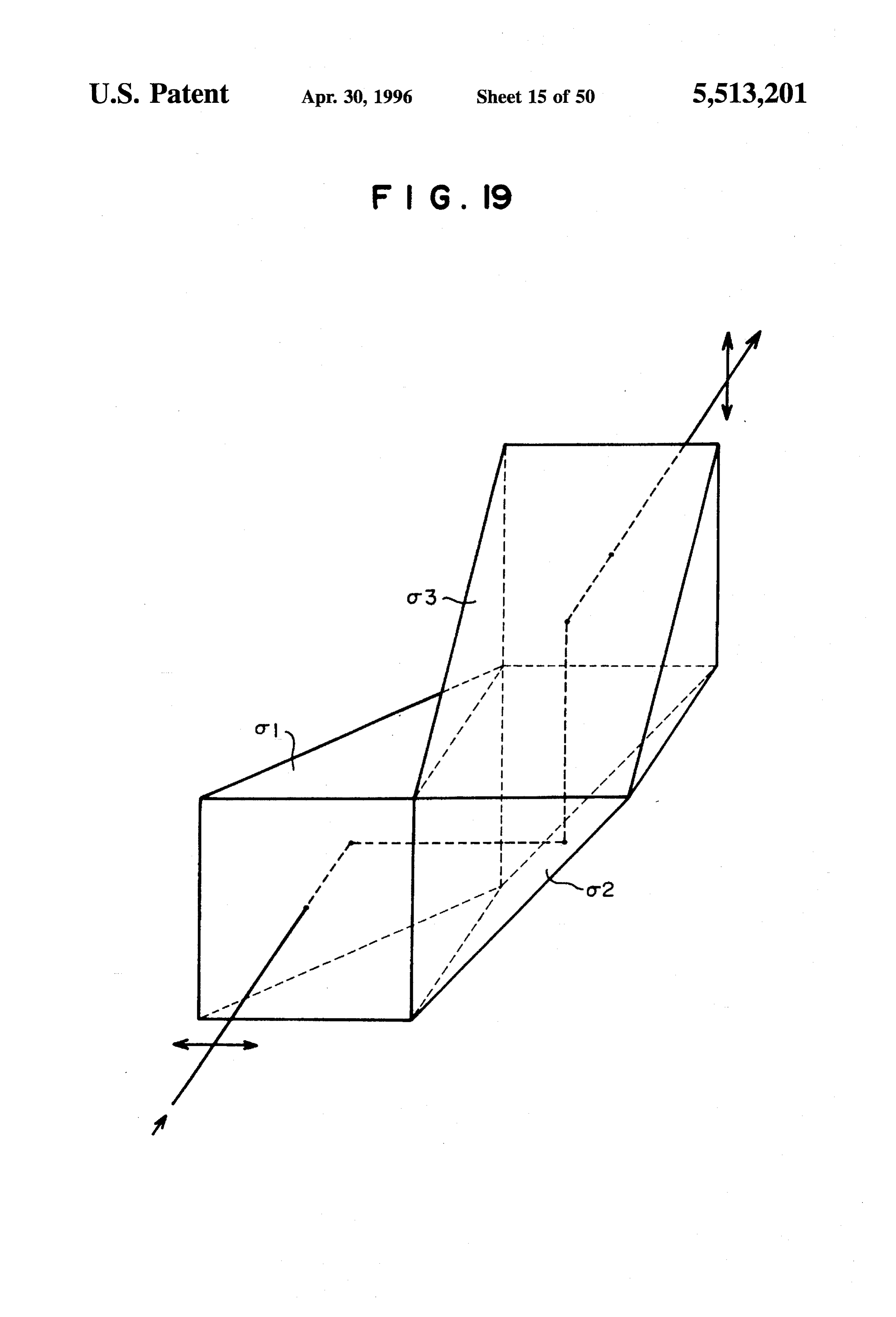
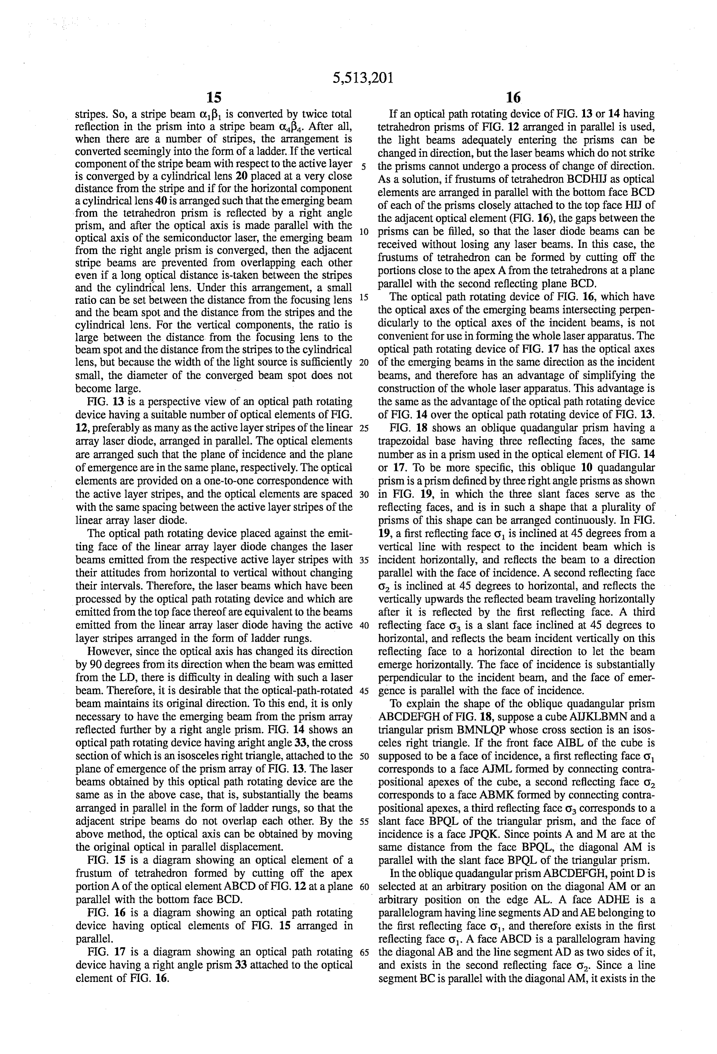
stripes. So, a stripe beam of is converted by twice total If an optical path rotating device of FIG. 13 or 14 having reflection in the prism into a stripe beam of. After all, tetrahedron prisms of FIG. 12 arranged in parallel is used, when there are a number of stripes, the arrangement is the light beams adequately entering the prisms can be converted seemingly into the form of a ladder. If the vertical changed in direction, but the laser beams which do not strike component of the stripe beam with respect to the active layer the prisms cannot undergo a process of change of direction. is converged by a cylindrical lens 20 placed at a very close As a solution, if frustums of tetrahedron BCDHIJ as optical distance from the stripe and if for the horizontal component elements are arranged in parallel with the bottom face BCD a cylindrical lens 40 is arranged such that the emerging beam of each of the prisms closely attached to the top face HIJ of from the tetrahedron prism is reflected by a right angle the adjacent optical element (FIG. 16), the gaps between the prism, and after the optical axis is made parallel with the 10 prisms can be filled, so that the laser diode beams can be optical axis of the semiconductor laser, the emerging beam received without losing any laser beams. In this case, the from the right angle prism is converged, then the adjacent frustums of tetrahedron can be formed by cutting off the stripe beams are prevented from overlapping each other even if a long optical distance is-taken between the stripes portions close to the apex. A from the tetrahedrons at a plane and the cylindrical lens. Under this arrangement, a small parallel with the second reflecting plane BCD. ratio can be set between the distance from the focusing lens 15 The optical path rotating device of FIG. 16, which have and the beam spot and the distance from the stripes and the the optical axes of the emerging beams intersecting perpen cylindrical lens. For the vertical components, the ratio is dicularly to the optical axes of the incident beams, is not large between the distance from the focusing lens to the convenient for use informing the whole laser apparatus. The beam spot and the distance from the stripes to the cylindrical optical path rotating device of FIG. 17 has the optical axes lens, but because the width of the light source is sufficiently 20 of the emerging beams in the same direction as the incident small, the diameter of the converged beam spot does not beams, and therefore has an advantage of simplifying the become large. construction of the whole laser apparatus. This advantage is FIG. 13 is a perspective view of an optical path rotating the same as the advantage of the optical path rotating device device having a suitable number of optical elements of FIG. of FIG. 14 over the optical path rotating device of FIG. 13. 12, preferably as many as the active layer stripes of the linear 25 FIG. 18 shows an oblique quadangular prism having a array laser diode, arranged in parallel. The optical elements trapezoidal base having three reflecting faces, the same are arranged such that the plane of incidence and the plane number as in a prism used in the optical element of FIG. 14 of emergence are in the same plane, respectively. The optical or 17. To be more specific, this oblique 10 quadangular elements are provided on a one-to-one correspondence with prism is a prism defined by three right angle prisms as shown the active layer stripes, and the optical elements are spaced 30 in FIG. 19, in which the three slant faces serve as the with the same spacing between the active layer stripes of the reflecting faces, and is in such a shape that a plurality of linear array laser diode. prisms of this shape can be arranged continuously. In FIG. The optical path rotating device placed against the emit 19, a first reflecting face o is inclined at 45 degrees from a ting face of the linear array layer diode changes the laser vertical line with respect to the incident beam which is beams emitted from the respective active layer stripes with 35 incident horizontally, and reflects the beam to a direction their attitudes from horizontal to vertical without changing parallel with the face of incidence. A second reflecting face their intervals. Therefore, the laser beams which have been o, is inclined at 45 degrees to horizontal, and reflects the processed by the optical path rotating device and which are vertically upwards the reflected beam traveling horizontally emitted from the top face thereof are equivalent to the beams after it is reflected by the first reflecting face. A third emitted from the linear array laser diode having the active 40 reflecting face O is a slant face inclined at 45 degrees to layer stripes arranged in the form of ladder rungs. horizontal, and reflects the beam incident vertically on this However, since the optical axis has changed its direction reflecting face to a horizontal direction to let the beam by 90 degrees from its direction when the beam was emitted emerge horizontally. The face of incidence is substantially from the LD, there is difficulty in dealing with such a laser perpendicular to the incident beam, and the face of emer beam. Therefore, it is desirable that the optical-path-rotated 45 gence is parallel with the face of incidence. beam maintains its original direction. To this end, it is only To explain the shape of the oblique quadangular prism necessary to have the emerging beam from the prism array ABCDEFGH of FIG. 18, suppose a cube AIJKLBMN and a reflected further by a right angle prism. FIG. 14 shows an triangular prism BMNLQP whose cross section is an isos optical path rotating device having aright angle 33, the cross celes right triangle. If the front face AIBL of the cube is section of which is an isosceles right triangle, attached to the 50 supposed to be a face of incidence, a first reflecting face o plane of emergence of the prism array of FIG. 13. The laser corresponds to a face AJML formed by connecting contra beams obtained by this optical path rotating device are the positional apexes of the cube, a second reflecting face o same as in the above case, that is, substantially the beams corresponds to a face ABMK formed by connecting contra arranged in parallel in the form of ladder rungs, so that the positional apexes, a third reflecting face o corresponds to a adjacent stripe beams do not overlap each other. By the 55 slant face BPOL of the triangular prism, and the face of above method, the optical axis can be obtained by moving incidence is a face JPOK. Since points A and M are at the the original optical in parallel displacement. same distance from the face BPOL, the diagonal AM is FIG. 15 is a diagram showing an optical element of a parallel with the slant face BPQL of the triangular prism. frustum of tetrahedron formed by cutting off the apex In the oblique quadangular prism ABCDEFGH, point Dis portion A of the optical element ABCD of FIG. 12 at a plane 60 selected at an arbitrary position on the diagonal AM or an parallel with the bottom face BCD. arbitrary position on the edge AL. A face ADHE is a FIG. 16 is a diagram showing an optical path rotating parallelogram having line segments AD and AEbelonging to device having optical elements of FIG. 15 arranged in the first reflecting face o, and therefore exists in the first parallel. reflecting face O. A face ABCD is a parallelogram having FIG. 17 is a diagram showing an optical path rotating 65 the diagonal AB and the line segment AD as two sides of it, device having a right angle prism 33 attached to the optical and exists in the second reflecting face O. Since a line element of FIG. 16. segment BC is parallel with the diagonal AM, it exists in the
Page 60
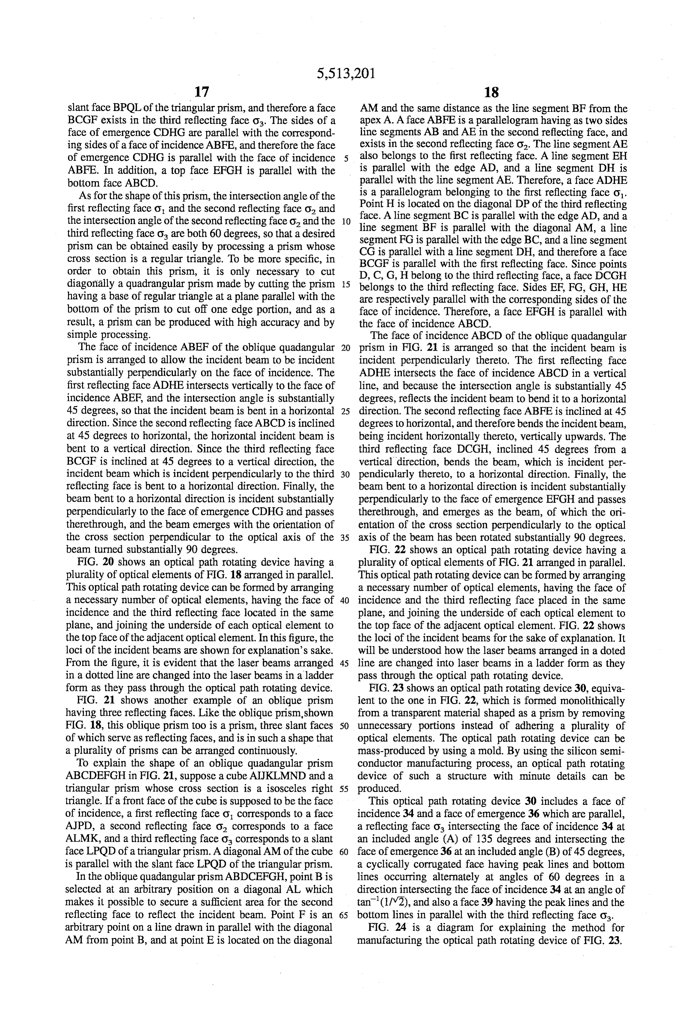
Slant face BPQL of the triangular prism, and therefore a face AM and the same distance as the line segment BF from the BCGF exists in the third reflecting face o The sides of a apex A. A face ABFE is a parallelogram having as two sides face of emergence CDHG are parallel with the correspond line segments AB and AE in the second reflecting face, and ing sides of a face of incidence ABFE, and therefore the face exists in the second reflecting face O. The line segment AE of emergence CDHG is parallel with the face of incidence also belongs to the first reflecting face. A line segment EH ABFE. In addition, a top face EFGH is parallel with the is parallel with the edge AD, and a line segment DH is bottom face ABCD, parallel with the line segment AE. Therefore, a face ADHE As for the shape of this prism, the intersection angle of the isPoint a parallelogram belonging to the first reflecting face o.
first reflecting face O and the second reflecting face o and face. AHline is located on the diagonal DP of the third reflecting the intersection angle of the second reflecting face o and the line segmentsegment 10 BC is parallel with the edge AD, and a third reflecting face O are both 60 degrees, so that a desired segment FG isBF is parallel with the diagonal AM, a line parallel with the edge BC, and a line segment prism can be obtained easily by processing a prism whose CG is parallel with a line segment DH, and therefore a face cross section is a regular triangle. To be more specific, in BCGF is parallel with the first reflecting face. Since points order to obtain this prism, it is only necessary to cut diagonally a quadrangular prism made by cutting the prism 5 belongs toH the
D, C, G, belong to the third reflecting face, a face DCGH third reflecting face. Sides EF, FG, GH, HE having a base of regular triangle at a plane parallel with the are respectively parallel with the corresponding sides of the bottom of the prism to cut off one edge portion, and as a face of incidence. Therefore, a face EFGH is parallel with result, a prism can be produced with high accuracy and by the face of incidence ABCD.
simple processing. The face of incidence ABCD of the oblique quadangular The face of incidence ABEF of the oblique quadangular 20 prism in FIG. 2 is arranged so that the incident beam is prism is arranged to allow the incident beam to be incident incident perpendicularly thereto. The first reflecting face substantially perpendicularly on the face of incidence. The ADHE intersects the face of incidence ABCD in a vertical first reflecting face ADHE intersects vertically to the face of line, and because the intersection angle is substantially 45 incidence ABEF, and the intersection angle is substantially degrees, reflects the incident beam to bend it to a horizontal 45 degrees, so that the incident beam is bent in a horizontal 25 direction. The second reflecting face ABFE is inclined at 45 direction. Since the second reflecting face ABCD is inclined degrees to horizontal, and therefore bends the incident beam, at 45 degrees to horizontal, the horizontal incident beam is being incident horizontally thereto, vertically upwards. The bent to a vertical direction. Since the third reflecting face third reflecting face DCGH, inclined 45 degrees from a BCGF is inclined at 45 degrees to a vertical direction, the vertical direction, bends the beam, which is incident per incident beam which is incident perpendicularly to the third 30 pendicularly thereto, to a horizontal direction. Finally, the reflecting face is bent to a horizontal direction. Finally, the beam bent to a horizontal direction is incident substantially beam bent to a horizontal direction is incident substantially perpendicularly to the face of emergence EFGH and passes perpendicularly to the face of emergence CDHG and passes therethrough, and emerges as the beam, of which the ori therethrough, and the beam emerges with the orientation of entation of the cross section perpendicularly to the optical the cross section perpendicular to the optical axis of the 35 axis of the beam has been rotated substantially 90 degrees. beam turned substantially 90 degrees. FIG. 22 shows an optical path rotating device having a FIG. 20 shows an optical path rotating device having a plurality of optical elements of FIG. 21 arranged in parallel. plurality of optical elements of FIG. 18 arranged in parallel. This optical path rotating device can be formed by arranging This optical path rotating device can be formed by arranging a necessary number of optical elements, having the face of a necessary number of optical elements, having the face of 40 incidence and the third reflecting face placed in the same incidence and the third reflecting face located in the same plane, and joining the underside of each optical element to plane, and joining the underside of each optical element to the top face of the adjacent optical element. FIG. 22 shows the top face of the adjacent optical element. In this figure, the the loci of the incident beams for the sake of explanation. It loci of the incident beams are shown for explanation's sake. will be understood how the laser beams arranged in a doted From the figure, it is evident that the laser beams arranged 45 line are changed into laser beams in a ladder form as they in a dotted line are changed into the laser beams in a ladder pass through the optical path rotating device. form as they pass through the optical path rotating device. FIG. 23 shows an optical path rotating device 30, equiva FIG. 21 shows another example of an oblique prism lent to the one in FIG. 22, which is formed monolithically having three reflecting faces. Like the oblique prism, shown from a transparent material shaped as a prism by removing FIG. 18, this oblique prism too is a prism, three slant faces 50 unnecessary portions instead of adhering a plurality of of which serve as reflecting faces, and is in such a shape that optical elements. The optical path rotating device can be a plurality of prisms can be arranged continuously. mass-produced by using a mold. By using the silicon semi To explain the shape of an oblique quadangular prism conductor manufacturing process, an optical path rotating ABCDEFGH in FIG. 21, suppose a cube AIJKLMND and a device of such a structure with minute details can be triangular prism whose cross section is a isosceles right 55 produced.
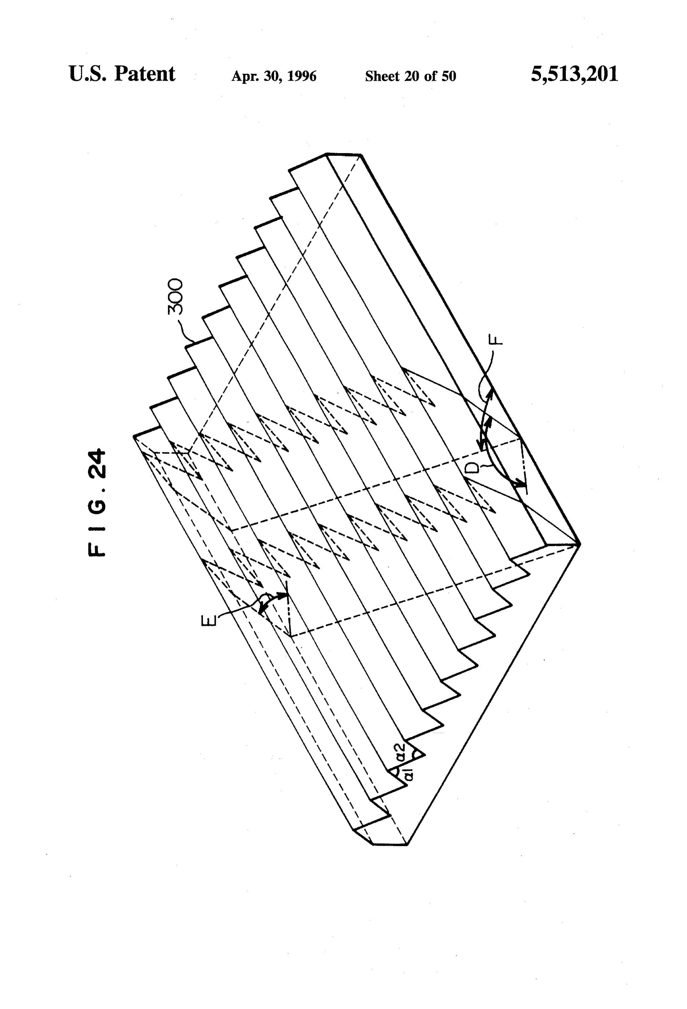
triangle. If a front face of the cube is supposed to be the face This optical path rotating device 30 includes a face of of incidence, a first reflecting face o corresponds to a face incidence 34 and a face of emergence 36 which are parallel, AJPD, a second reflecting face o corresponds to a face a reflecting face o intersecting the face of incidence 34 at ALMK, and a third reflecting face o corresponds to a slant an included angle (A) of 135 degrees and intersecting the face LPQD of a triangular prism. A diagonal AM of the cube 60 face of emergence 36 at an included angle (B) of 45 degrees, is parallel with the slant face LPQD of the triangular prism. a cyclically corrugated face having peak lines and bottom In the oblique quadangular prism ABDCEFGH, point B is lines occurring alternately at angles of 60 degrees in a selected at an arbitrary position on a diagonal AL which direction intersecting the face of incidence 34 at an angle of makes it possible to secure a sufficient area for the second tan (1/V2), and also a face 39 having the peak lines and the reflecting face to reflect the incident beam. Point F is an 65 bottom lines in parallel with the third reflecting face o arbitrary point on a line drawn in parallel with the diagonal FIG. 24 is a diagram for explaining the method for AM from point B, and at point E is located on the diagonal manufacturing the optical path rotating device of FIG. 23.
Page 61
As shown in FIG. 24, a plate material 300 is made of a pitches about equivalent to the pitches of the prism elements transparent material (glass, quartz, or the like) having front arranged.
and rear faces parallel with each other, one face (the upper However, it goes without saying that preferably, the prism face in FIG. 24) which has a cyclically corrugated face of a elements should be arranged on a one-to-one correspon cross section of a triangular wave with apex angles of 60 dence with the stripe beams for convergence to smaller degrees and bottom angles of 60 degrees. An optical path beams. In actual applications, even when the active layer rotating device 32 can be obtained by cutting the plate stripes are arranged at pitches of or in widths of 100 um or material 300 at two parallel planes which are at an angle D less, it is possible to produce an optical path rotating device (E) of 135 degrees (or 45 degrees) from the other face having the reflecting faces on a one-to-one correspondence with the active layers by using a silicon semiconductor (bottom face in FIG. 24) with an angle Fformed on the other 10 process face with the peak lines and bottom lines of the triangular or an LIGA process.
wave being tan v2. FIG. 27 is a diagram showing a composite prism includ The principle of optical path change in the above-men ing tetrahedron prisms of FIG. 12 combined symmetrically tioned embodiment will be described with reference to FIG.
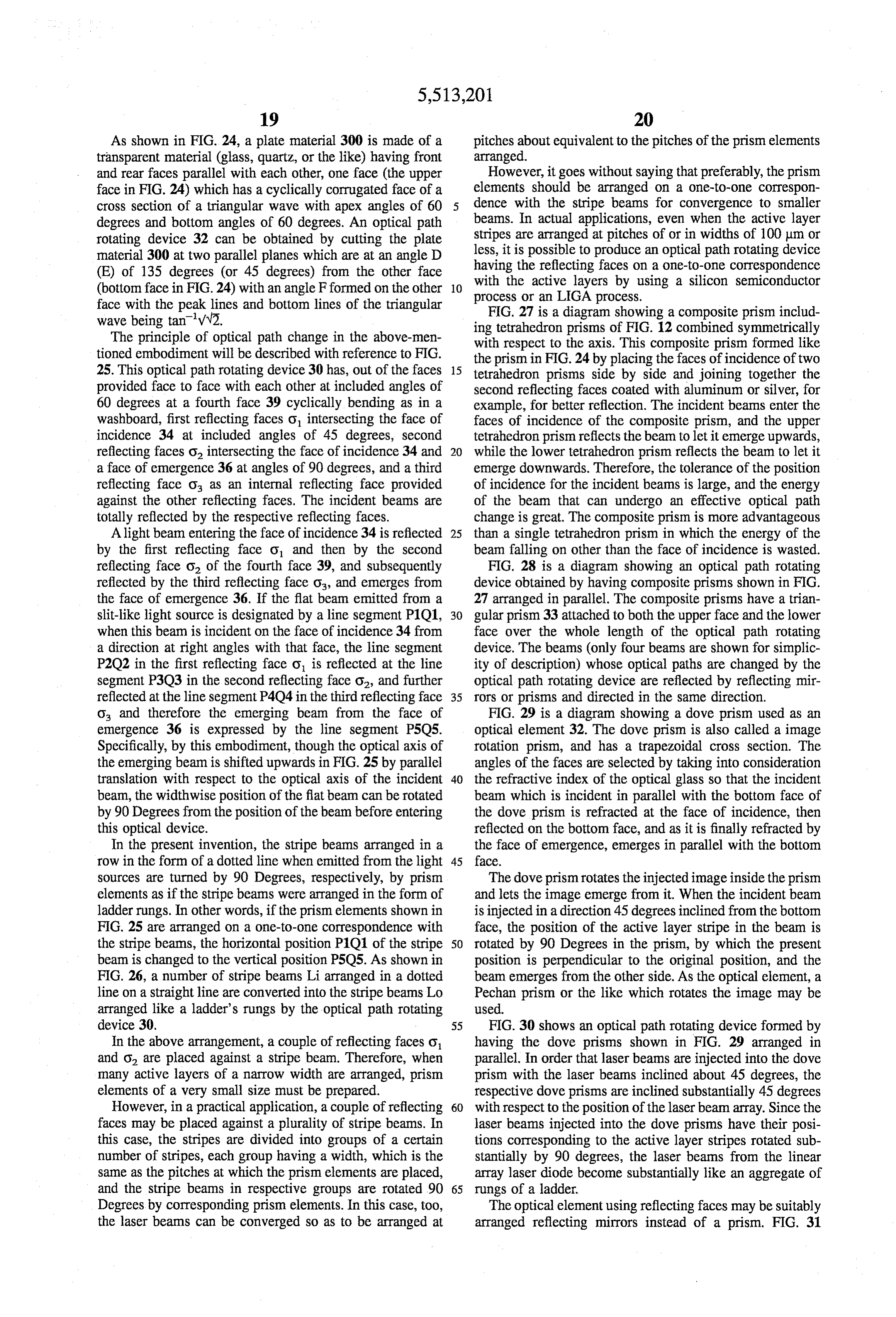
with respect to the axis. This composite prism formed like the prism in FIG.24 by placing the faces of incidence of two 25. This optical path rotating device 30 has, out of the faces 15 tetrahedron prisms side by side and joining together the provided face to face with each other at included angles of second reflecting faces coated with aluminum or silver, for 60 degrees at a fourth face 39 cyclically bending as in a example, for better reflection. The incident beams enter the washboard, first reflecting faces o intersecting the face of faces of incidence of the composite prism, and the upper incidence 34 at included angles of 45 degrees, second tetrahedron prism reflects the beam to let it emerge upwards, reflecting faces o intersecting the face of incidence 34 and 20 while the lower tetrahedron prism reflects the beam to let it a face of emergence 36 at angles of 90 degrees, and a third emerge downwards. Therefore, the tolerance of the position reflecting face oa as an internal reflecting face provided of incidence for the incident beams is large, and the energy against the other reflecting faces. The incident beams are of the beam that can undergo an effective optical path totally reflected by the respective reflecting faces. change is great. The composite prism is more advantageous Alight beam entering the face of incidence 34 is reflected 25 than a single tetrahedron prism in which the energy of the by the first reflecting face o and then by the second beam falling on other than the face of incidence is wasted. reflecting face o of the fourth face 39, and subsequently FIG. 28 is a diagram showing an optical path rotating reflected by the third reflecting face o and emerges from device obtained by having composite prisms shown in FIG. the face of emergence 36. If the flat beam emitted from a 27 arranged in parallel. The composite prisms have a trian slit-like light source is designated by a line segment P1O1, 30 gular prism 33 attached to both the upper face and the lower when this beam is incident on the face of incidence 34 from face over the whole length of the optical path rotating a direction at right angles with that face, the line segment device. The beams (only four beams are shown for simplic P2O2 in the first reflecting face o is reflected at the line ity of description) whose optical paths are changed by the segment P3O3 in the second reflecting face o and further optical path rotating device are reflected by reflecting mir reflected at the line segment P4Q4 in the third reflecting face 35 rors or prisms and directed in the same direction. o, and therefore the emerging beam from the face of FIG. 29 is a diagram showing a dove prism used as an emergence 36 is expressed by the line segment PSQ5. optical element 32. The dove prism is also called a image Specifically, by this embodiment, though the optical axis of rotation prism, and has a trapezoidal cross section. The the emerging beam is shifted upwards in FIG.25 by parallel angles of the faces are selected by taking into consideration translation with respect to the optical axis of the incident 40 the refractive index of the optical glass so that the incident beam, the widthwise position of the flat beam can be rotated beam which is incident in parallel with the bottom face of by 90 Degrees from the position of the beam before entering the dove prism is refracted at the face of incidence, then this optical device. reflected on the bottom face, and as it is finally refracted by In the present invention, the stripe beams arranged in a the face of emergence, emerges in parallel with the bottom row in the form of a dotted line when emitted from the light 45 face.
sources are turned by 90 Degrees, respectively, by prism The dove prism rotates the injected image inside the prism elements as if the stripe beams were arranged in the form of and lets the image emerge from it. When the incident beam ladder rungs. In other words, if the prism elements shown in is injected in a direction 45 degrees inclined from the bottom FIG. 25 are arranged on a one-to-one correspondence with face, the position of the active layer stripe in the beam is the stripe beams, the horizontal position PO1 of the stripe 50 rotated by 90 Degrees in the prism, by which the present beam is changed to the vertical position PSQ5. As shown in position is perpendicular to the original position, and the FIG. 26, a number of stripe beams Li arranged in a dotted beam emerges from the other side. As the optical element, a line on a straight line are converted into the stripe beams Lo Pechan prism or the like which rotates the image may be arranged like a ladder's rungs by the optical path rotating used.
device 30, 55 FIG. 30 shows an optical path rotating device formed by In the above arrangement, a couple of reflecting faces o having the dove prisms shown in FIG. 29 arranged in and O. are placed against a stripe beam. Therefore, when parallel. In order that laser beams are injected into the dove many active layers of a narrow width are arranged, prism prism with the laser beams inclined about 45 degrees, the elements of a very small size must be prepared. respective dove prisms are inclined substantially 45 degrees However, in a practical application, a couple of reflecting 60 with respect to the position of the laser beam array. Since the faces may be placed against a plurality of stripe beams. In laser beams injected into the dove prisms have their posi this case, the stripes are divided into groups of a certain tions corresponding to the active layer stripes rotated sub number of stripes, each group having a width, which is the stantially by 90 degrees, the laser beams from the linear same as the pitches at which the prism elements are placed, array laser diode become substantially like an aggregate of and the stripe beams in respective groups are rotated 90 65 rungs of a ladder.
Degrees by corresponding prism elements. In this case, too, The optical element using reflecting faces may be suitably the laser beams can be converged so as to be arranged at arranged reflecting mirrors instead of a prism. FIG. 31
Page 62
shows an optical element which performs the same function prism, the cross section of which is a rectangle, at prede as the prism in FIG. 12. By cutting out apart of the cube, two termined pitches instead of adhering unit optical elements. A reflecting mirror faces are formed: the first mirror face o is front face DEIH and a top face DGKH intersect at a right formed which is inclined 45 degrees to reflect the incident angle, and recessed portions B1R1S2C2S3R2, formed along beam perpendicularly in a horizontal plane, and a second the edge DH by a vertical face C2B1R2S3 intersecting the mirror face O to reflect the reflected beam from the first front face DEIH at 45 degrees and a face C2B1R1S2 which reflecting mirror face vertically upwards. The first and is perpendicular to the front face and intersects the top face second reflecting mirror faces intersect at an intersection DGKH at 45 degrees, are formed at pitches corresponding to angle of 60 degrees. For the material of this optical element, the active layer stripes of the linear array laser diode. By applying the silicon semiconductor manufacturing process, metal, metal-plated glass, plastics, silicon or the like may be 10 an used. FIG. 32 shows an optical path rotating device which is optical path rotating device of such a minute structure can be manufactured.
formed as a mirror array by having the optical elements of FIG. 36 is a diagram of an optical path rotating device FIG. 31 arranged so as to correspond to the active layer which bends 90 degrees the direction of the laser beam stripes of the linear array laser diode. The laser beams emerging vertically upwards by the optical path rotating emitted from the active layer stripes are bent 90 degrees and 5 device so as to let the beam emerge in the same direction as their positions corresponding to the stripes are turned 90 the direction of incidence. The light beam traveling verti degrees, so that the laser beams of the linear array laser cally upwards, after being reflected in the space placed diode are arranged substantially in the form of ladder rungs. between the reflecting mirrors, enters vertically the bottom Tiny optical elements corresponding to the active layer side of the prism, and is bent 90 degrees by a slant face, and stripes of the linear array laser diode can be produced by 20 emitted in the same direction as the optical axis of the using a precision mold, a silicon semiconductor manufac incident beam.
turing process or an LIGA process. When a silicon crystal is In the embodiment of FIG. 36, the optical path is changed used, if its cleavage planes are used as reflecting mirror by a right angle prism, but instead of the right angle prism, faces, the crystal can be processed easily. Instead of adhering reflecting mirrors may be used. FIG. 37 is a diagram optical elements, by cutting off some parts at one edge of a 25 showing an optical path rotating device constructed by prism by the silicon semiconductor process, an optical path providing a third reflecting mirrorface O on the top face of rotating device as shown in FIG. 32 can be formed. In this the optical path rotating device of FIG. 35 to bend 90 case, a strong and accurate optical path rotating device can degrees the direction of the laser beam made to travel be produced by a relatively simple manufacturing method. vertically upwards by the optical path rotating device of FIG.33 is a diagram showing another optical path rotating 30 FIG. 35 so as to be emitted in the same direction as the device having the same function as the one shown in FIG. direction of incidence. The beam which is reflected by 32. The optical element 32 is formed by removing a tetra mirror-finished reflecting mirrors O, and o and emitted hedron A1C1A2B1 having isosceles right triangles A2A1B1 vertically upwards, and falls on a mirror-finished third and A1A2C1 as its two faces from an upper bottom reflecting mirror O at an incidence angle of 45 degrees with A1A2N2N1 and the front face A1L1L2A2 in a prism having 35 respect to the bottom side of the optical path rotating device, parallelograms with opposite angles A1A2N2, A1N1N2, and the beam is emitted in the same direction as the optical and L1L2M2, L1M1M2 as the upper bottom A1A2N2N1 axis 10 of the incident beam. This embodiment offers an and a lower bottom L1L2M2M1. The optical path rotating advantage that any material can be used if it accepts any device 32 is formed by cutting the above-mentioned prism mirror finish.
at a face A1B1C1 which is inclined at 45 degrees to 40 FIG.38 shows an optical path rotating device 30 formed horizontal, includes a line AB1 forming an angle of 45 for easy handling by mounting a plurality of optical ele degrees by connecting an apex A1, point B1 on an edge ments 32 on a transparent disc 39. The disc is 3 mm thick A2N2, and an apex A2. The face A1C1B1 of the optical and 30 mm in diameter. The optical path rotating device is element 32 and a part A2B1C1 of a face of the adjacent joined at its face of emergence to the disk with an adhesive optical element, which have the tetrahedron void space, are 45 having the same refractive index as that of the materials of mirror-finished. The optical path rotating device 30 of FIG. optical elements and the disc. Optical elements are fixed at 33 formed as described has the same function as the optical fixed positions on a disc, in other words, the unified optical path rotating device of FIG. 32, and the incident beam path rotating device 30 is placed at a specified position on a entering the first reflecting face O is rotated by 90 degrees disc, and by using a disc of an adequate size, the optical path and emerges from the second reflecting face O2. 50 rotating device 30 can be controlled so as to be located in a FIG. 34 is a diagram showing the optical path rotating desired position.
device 30 in which the recessed portions in the optical path FIG. 39 is a diagram showing an optical path rotating rotating device of FIG.33 are further deepened. The optical device 30 joined to a collimating cylindrical lens 40 instead path rotating device 32 has the same function as the prism of the disc shown in FIG. 38. As for the cross section of the in FIG. 15, and is in the shape that has the portion including 55 collimator lens, the face of incidence is flat and the face of the apex A1 cut off, and has a trapezoidal reflecting face emergence is spherical. It be desirable that the lens is thick S1R1B1C1 as the second reflecting mirror face O. The face and the focal distance long. The optical path rotating device L1M1N1R1S1 of the optical element is the first reflecting 30 is formed by arranging a plurality of optical elements and mirror face o. The beam incident horizontally on the first joining them to the flat face of the lens with an adhesive reflecting mirror face o is reflected twice and emerges 60 having an adequate refractive index. By use of the collimator vertically upwards from the second reflecting mirrorface O2. and the optical path rotating device constructed as described, The optical path rotating device has a larger tolerance of the component parts of the whole semiconductor laser position of incidence of the incident beam and the energy of apparatus can be reduced, so that the man-hours for the the laser beam, a large proportion of which can be subjected assembly process can be greatly reduced. to optical path change. 65 The optical path rotating device may be one that uses a FIG. 35 is a diagram showing a monolithic optical path lens of linearly-distributed refractive index as the optical rotating device formed by cutting out some portion of a element.
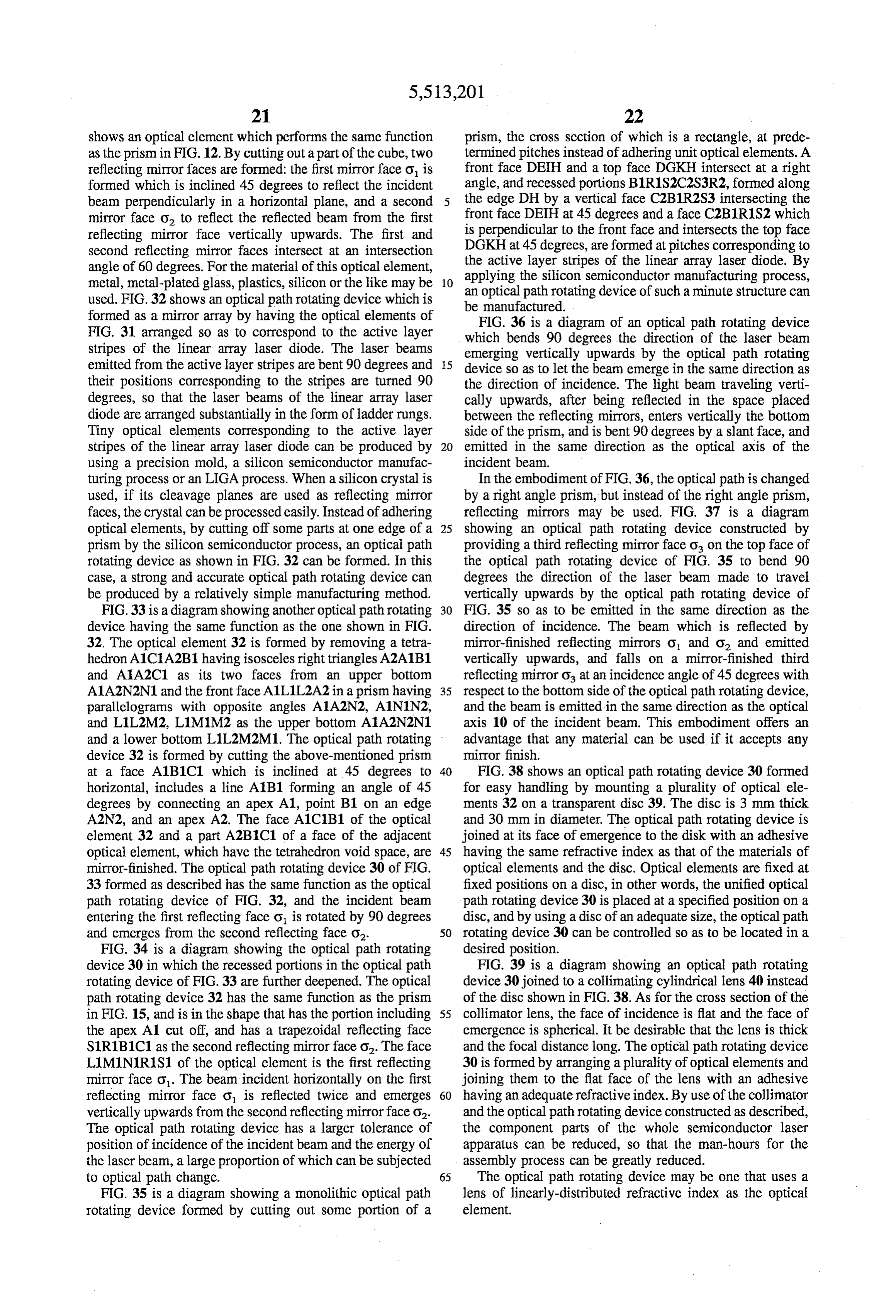
Page 63
FIG. 40 is a diagram for explaining the function of a lens In the optical path rotating device of the present invention, of linearly-distributed refractive index, and FIG. 41 is a the stripe beams lined up in the form of a dotted line when perspective view of an optical element using a linearly emitted from the light sources are respectively rotated 90 distributed refractive index lens. degrees as they pass through the linearly-distributed refrac Description will be made of the principle of optical path tive index lens elements 32, and emerge from the device as change of an optical path rotating device according to this if they were originally arranged in parallel in the form of embodiment. FIG. 40 is a cross sectional view of a lens ladder rungs. More specifically, when an optical path rotat element 32 of linearly-distributed refractive index with an ing device 30 formed to have a plurality of the linearly optical axis length L of 0.5 pitch (the pitch represents the distributed refractive index lens elements 32 shown in FIG. rotational period of the beam in the lens) used in this 10 41 arranged on a one-to-one correspondence with the stripe invention. This linearly-distributed refractive index lens element 32 is made of a flat optical glass body. In the linear beams, a plurality of flat stripe beams lined up in a straight line like a dotted line, emitted from the semiconductor laser distribution of refractive index across the width, the highest generating elements, are incident on the corresponding lin refractive index value no is located in the center plane indicated by the solid two-dot chain line, and as approaching 15 early-distributed refractive index lens elements 32. The towards either side face in the width direction, the refractive emerging beams, as the positions of the flat beams are turned index values decrease gradually. For example, the maximum 90 degrees from the position when entering the device 30, refractive index value no is about 1.6, and the difference and therefore the stripe beams are arranged like ladder from the refractive index values at both end face portions is rungs.
about 0.05. The lens length L conducive to 0.5 pitch is about Many stripe beams Li arranged as a short dashed line on 10 mm. The lens length L to give 0.5 pitch may change 20 a straight line as described above are converted by the according to the correlation with the refractive index distri optical path rotating device 30 into stripe beams Lo arranged bution characteristics. in parallel like ladder rungs as if they were originally emitted The incident beams a, b, d, and e of light entering from the that way.
face of incidence located at the upper position in FIG. 40 In the above-mentioned arrangement, one linearly-distrib advance through the lens marking the curves according to 25 uted refractive index lens element 32 is placed against a the difference in refractive index at the portions through stripe beam. Therefore, when a large number of active layers which the beams travel, and emerge as the emerging beams having small width are arranged, it is necessary to prepare a', b', d'and e' from the face of emergence. The beam c of linearly-distributed refractive lens elements of very small light incident on the center portion passes straight through the center portion of the lens, and emerges as the beam c'. 30 distributed refractive index manufacture, size. However, in practical a single linearly lens element may be used to
The conventional distributed-refractive-index lens is gen cover a plurality of stripe beams. In this case, the stripes are erally a cylindrical optical glass body in which the refractive index is highest on the central axis and decreases towards the divided into groups of a certain number of stripes, each peripheral portions perpendicular to the radiating direction. group having a width, which is the same as the pitches at The refractive index distribution is formed by using ion 35 which the linearly-distributed refractive index lens elements diffusion distribution obtained by immersing the glass in a are arranged, and the stripe beams in respective groups are molten salt to cause the monovalentions such as silver ions rotated 90 degrees by corresponding lens elements. In this (Ag) previously doped in the glass to be exchanged by case, too, the laser beams can be converged so that their alkali ions. There is also a known type which has the pitches are about equivalent to the pitches of the linearly refractive index varied in the optical axis direction to correct distributed refractive index lens elements arranged. the spherical aberration of the lens. If a flat glass pane is used 40 FIG. 43 is a perspective view of an optical element as in this embodiment instead of the cylindrical lens, by formed by another linearly-distributed refractive index lens. suitably setting the time of ion diffusion, the refractive index This optical element 32 is made of a flat optical glass, and distribution is formed such that the refractive index is high its widthwise linearly-distributed refractive index profile in a plane at the center position and low towards the side shows a monotonic decreasing pattern. When a flat laser faces. 45 beam is incident on the face of incidence as it is suitably When a linearly-distributed refractive index lens element inclined with respect to the face of the optical element, the 32 as mentioned above is arranged such that the planes beam is refracted to a direction of high refractive index parallel with the optical axis are inclined at 45 degrees to according to the refractive index distribution, and after being horizontal as shown in FIG. 41 and the beams from a linear totally reflected by the side face, emerges from the face of light sources flat in the horizontal direction of the incident 50 emergence marking a refractive locus in contrast to that of beams are incident on the face of incidence 34 located at the the incident beam. By suitably selecting a refractive index lower position of the sheet of the diagram, if the line distribution and the length of the optical element, it is segment at the face of incidence 34 is designated by P1O1, possible to make an arrangement that when the beam enters the beams in the line segment P1O1 pass through the lens, the optical element with the widthwise position inclined 45 separately marking respective curves. The line segment 55 degrees, the emerging beam emerges with the 10 widthwise P2Q2 at a position where the rotational period is 0.5 pitch, position inclined 90 degrees. By arranging optical elements which is the intermediate point of the optical pathin the lens, designed as described in a row each inclined 45 degrees, the is inclined at 45 degrees from its position at the time of optical path rotating device of the present invention can be incidence for the highest refractive index no in other words, obtained. This optical element is advantageous in that lies along the centerplane. At the face of emergence 36, the 60 because the refractive index varies in a monotonic pattern beams are further rotated 45 degrees to form the line from one end face of the plate, a specified refractive index segment P3O3 tilted vertically, and emerge from the face of distribution can be formed, and that the manufacturing emergence. In short, the positions of the flat beams are. process is simple.
rotated 90 degrees in the lens. FIG. 44 is a diagram showing an optical path rotating FIG. 42 is a diagram showing an optical path rotating 65 device having arranged at the corresponding positions on device having linearly-distributed refractive index lenses as either side of the optical glass body semi-cylindrical por the optical elements arranged in a row. tions each with the refractive index decreasing in a concen
Page 64
tric pattern. The semi-cylindrical refractive index distribu further rotated at the cylindrical face of the 45-degree tion such as this can be formed by preparing an optical glass inclined face of emergence for a total of substantially 90 having a specified thickness and doped with monovalent degrees, and the beam emerges from the face of emergence. ions such as silver ions, and immersing the optical glass in As has been described, the stripe beams from the linear array a molten salt with a mask having slanting-line openings laser diode are converted into the beams substantially in the inclined 45 degrees applied to the face of incidence and the form of ladder rungs. If the optical elements are so posi face of emergence of the optical glass to cause the above tioned as to match the pitches of the stripe beams, the optical mentioned monovalent ions to be exchanged by alkali ions. elements need not have parallel side faces, and a cylindrical In the flat beam incident horizontally on the face of inci lens with a true circle cross section can be used. dence, the beam axis is rotated by being subjected to the 10 FIG. 48 shows an optical path rotating device made from refracting powers which differ with different positions of an optical glass block. A plurality of cylindrical faces, incidence at the 45-degree-inclined semi-cylindrical por inclined 45 degrees in the same direction, are formed both tions, and becomes parallel with the axis of the semi on the incidence and emergence faces of an optical glass cylindrical portion in the middle of the optical path rotating prism of a rectangular cross section. This optical path device. When the beam reaches the semi-cylindrical portion 15 rotating device has the same function as the one shown in at the face of emergence, has the axis of the flat beam further FIG. 47. The optical path rotating device may be one rotated, and emerges from the face of emergence with the including optical elements utilizing diffraction. beam axis substantially 90 degrees different from the posi FIGS. 49A and 49B show diagrams of an optical element tion of the axis of the incident beam. In the manner as using binary optics. This optical element is made by forming described, the stripe beams of the linear array laser diode are 20 many grooves with depths varying symmetrically with converted into the beams arranged substantially like the respect to the center axis in a direction perpendicular to the rungs of a ladder. axis of a transparent plate. Among optical elements obtain The optical path rotating device of FIG. 44 obviates the able by binary optics, there is a multilevel diffractive lens, need to set and join a plurality of optical elements manu for example, in which the depths of the grooves are formed factured separately, and can be manufactured easily by 25 by utilizing diffraction so as to vary such that the diffraction performing an ion diffusion process on a flat glass. angle increases from the center to the outer portions (Refer FIG. 45 is a diagram showing an optical path rotating to Swanson et al. U.S. Pat. No. 4,895,790). Binary optics device having cylindrical lenses arranged side by side with mentioned above use optical glass and plastics, and can also each other. This optical path rotating device is formed by be produced using a mold.
arranging in two parallel lines cylindrical lenses of a cross 30 FIGS. 50A and 50B show diagrams of an optical element section of a bow shape formed by a straight line and an arc using a laminar type Fresnel zone plate. This optical element with the lens axes inclined 45 degrees and with the two lines has many square-wave-like grooves formed at different separated by a suitable distance. In the flat beam incident intervals symmetrically with respect to the center axis in a horizontally on the face of incidence, the axis of the flat direction perpendicular to the axis of a transparent plate. The beam is rotated by being subjected to different refracting 35 intervals of the grooves vary such that the diffraction angle powers at different positions of incidence by a 45-degree to the incident beams increases from the center to the outer inclined cylindrical lens, and further rotated 45 degrees at portions. The Fresnel plate with square-wave-like grooves the face of emergence for a total rotation of 90 degrees, and such as this can be obtained by an etching method or a emerges from the face of emergence. By using this optical replica method.
path rotating device, the stripe beams from the linear array 40 FIG. 51 is a diagram showing an optical element using a laser diode are converted into the beams substantially in the mask type Fresnel Zone plate. This optical element has many form of the rungs of a ladder. slits with varying intervals formed symmetrically with FIG. 46 is a diagram showing an optical path rotating respect to the center axis in a direction perpendicular to the device having cylindrical lenses of another type arranged in axis of a transparent plate. The intervals of the slits vary such two parallel lines. This optical path rotating device is formed 45 that like in the optical element using a Fresnel plate in FIG. by arranging face-to-face with each other in two parallel 50, the diffraction angle to the incident beams increases from lines cylindrical lenses of a cross section formed by two arcs the center to the outer portions. The Fresnel Zone plate with with the lens axes inclined 45 degrees and with a space slits such as this can be obtained by forming slits by using provided between the two lines. Since the cylindrical lenses an opaque mask.
of this type have a greater degree of freedom in design than 50 FIG. 52 is a diagram showing an optical path rotating the cylindrical lens of FIG. 45, an accurate optical path device made by forming diffraction-applied optical elements rotating device can be produced. Depending on the refrac on the face of incidence and the face of emergence, and tive index, curvature, and distance between the face of arranging two rows of the optical elements facing each other incidence and the face of emergence of the lens, the cross across a space provided as in the case shown in FIG. 45. This section of the cylindrical lens may be a true circle, and if the 55 optical path rotating device has optical elements, the axes of cross section is a circle, the optical path rotating device can which are inclined at 45 degrees to horizontal, arranged in be produced easily. parallel such that a pair of optical elements faces the FIG. 47 shows an optical path rotating device having corresponding active layer stripe of the linear array laser joined together a plurality of optical elements made of diode. When the beams flat in a horizontal direction fall on optical glass each having cylindrical faces of incidence and 60 the device, since the diffraction angle increases with an emergence, parallel side faces, and a dense interior. Each increasing distance from the center in each optical element, optical element is inclined at 45 degrees to horizontal. In the when the beams pass through the incidence face plate, the flat beam incident horizontally on the face of incidence, the axes of the flat beams rotate in the direction approaching the axis of the flat beam is rotated by being subjected to different center axes, and after reaching the emergence face plate, the refracting powers at different positions of incidence, which 65 beams are rotated at the face of incidence by the same are produced on the cylindrical face of the 45-degree amount in the same direction on the light reversibility inclined face of emergence, and the axis of the flat beam is principle, and emerge with the axes of the flat beams rotated
Page 65
for a total of about 90 degrees in the long run. This function semiconductor laser elements. This apparatus is provided is exactly the same as in FIG. 45. with a polarization beam splitter PBS 90 between a second cylindrical lens 40, and another second cylindrical lens 40'
Embodiment 3 and a focusing lens 50. The polarization beam splitter 90 has FIG. 53 is a block diagram for explaining the semicon a high reflective film for one and a low reflective film for the ductor-laser-pumped solid state laser apparatus of the other of linearly polarized luminous fluxes, the polarization present invention. This semiconductor-laser-pumped solid directions of which intersect at right angles. Output beams state laser apparatus uses the semiconductor laser apparatus of two linear array semiconductor laser elements 10 and 10' are arranged to intersect at right angles, and at the intersect of embodiment 1 as alight source for pumping the solid state O ing position, a polarization beam splitter PBS 90 is placed, laser 80. The conventional semiconductor laser apparatus so that one output passes straight through PBS 90 and the using a linear array laser diode could not produce a sub other output is reflected by the reflecting face of PBS90, and stantially high energy density even though it concentrates the two output beams are combined and are incident on the the energy of the beams by an optical system because the focusing lens 50 which focuses the beams on the pumping energy is concentrated only in an elongated spot. When it is required to produce a high power output effectively, the only 5 face of the solid state laser 80. In order that the polarization directions of the two laser beams intersectat right angles, the possible laser configuration is a side pumped laser. In semiconductor laser apparatuses are installed so as to be at contrast, in the semiconductor-laser-pumped solid state laser a right angle to each other. Under this arrangement, outputs apparatus of this embodiment, dotted-line-like stripe beams of a linear laser diode 10 are first condensed in a direction 20 of the two semiconductor laser elements can be utilized, so that the laser apparatus can produces twice as much output perpendicular to the active layer stripes by a first cylindrical as in other embodiments.
lens with a short focal distance f, and then converted into FIG. 56 is a diagram showing another type of the semi laser beams in the form of rungs of a ladder by using an conductor-laser-pumped solid state laser apparatus for optical path rotating device 30. After the ladder-rung-shaped laser beams are condensed in the widthwise direction by a 25 pumped solid state laser apparatusIn in obtaining doubled output power. the semiconductor-laser second cylindrical lens 40 with a long focal distance f, the ductor laser apparatuses are installedFIG.55, at a the semicon right angle with energy is converged in a small area on the light-receiving face of the solid state laser 80 by a focusing lens 50. The each other to have the polarization directions intersecting at semiconductor laser apparatus of embodiment 1, as a right angle. Instead, in this embodiment, a half wave plate 95 is placed for one of the outputs to pass therethrough. In described earlier, can concentrate the energy in a specified 30 FIG.
narrow area by the condensing power which varies with the 56, the linearly-polarized luminous flux from the vertical direction f/f, and the widthwise direction f/. For semiconductor laser apparatus located to the left of the this reason, the semiconductor-laser-pumped solid state polarization beam splitter 90 passes 100% through the laser apparatus of the present patent application, in which polarization beam splitter. On the other hand, when the linearly-polarized luminous flux from the semiconductor the semiconductor laser apparatus of embodiment 1 is used, 35 laser can make effective use of output of the linear array laser 90 inapparatus drawn above the polarization beam splitter FIG. 56 passes through a V2 wave plate 95, the diode 10 and enables the solid state laser 80 to be also pumped by end pumping. As the solid state laser element, in polarization direction is rotated 90 degrees, so that the addition to ordinary solid state elements such as a YAG or luminous flux is reflected 100% by the polarizing film on the YLF laser, a solid state laser including a Q switch or a 40 the polarization beam splitter. Thus, the luminous fluxes from wavelength changing element can be used. The light beam two semiconductor laser apparatuses are combined and may be injected from a pumping light source into the solid radiated to the pumping face of the solid state laser apparatus state laser element at a Brewstar angle. The solid state laser 80, thereby pumping the solid state laser element. According element may be a short absorption length laser crystal to the structure of the apparatus, the widthwise dimension of (YVO). With the semiconductor-laser-pumped solid state 45 theWe apparatus can be decreased.
claim:
laser apparatus of the present invention, a YAG laser output 1. A semiconductor laser apparatus comprising: of 3 W is obtained by using a 10-W semiconductor laser element. a linear array laser diode, having a plurality of laser FIG. 54 is a block diagram for explaining an optical-fiber beam-emitting emitters having emitter faces arranged guided semiconductor-laser-pumped solid state laser appa 50 to extend linearly in a first direction for emitting a ratus. This optical-fiber-guided semiconductor-laser group of laser beams in a form of a dotted line; pumped solid state laser apparatus uses an optical fiber 60 to a first condenser, disposed in front of said linear array guide output of the semiconductor laser apparatus of laser diode, for collimating said group of laser beams embodiment 1 to pump the solid state laser 80. The output by refracting them to a direction substantially perpen end of the optical fiber is provided with an optical system 70 55 dicular to said first direction; for collimating and once again converging the energy of the an optical path rotating device, disposed in front of said laser beam which diverges from the end portion. As first condenser, having arranged in parallel a plurality described, since there is a flexible optical fiber between the of optical elements for bending substantially at a right semiconductor laser apparatus and the solid state laser unit, angle an axis of a cross section of at least a laser beam, the apparatus is provided with a greatly increased degree of 60 for receiving the group of laser beams collimated in freedom, and can be configured more easily. With the said second direction, and emitting the group of laser optical-fiber-guided semiconductor-laser-pumped solid state beams substantially in the form of ladder rungs lined up laser apparatus, a YAG laser output of 2W is obtained from in said first direction by rotating the axis of the cross a 10-W semiconductor laser element. section of the laser beams for each of said optical FIG.55 is a block diagram for explaining a semiconduc 65 elements;
tor-laser-pumped solid state laser apparatus for obtaining a second condenser for collimating said group of laser doubled output power made by using two linear array beams substantially in the form of ladder rungs by
Page 66
refracting the beams to a direction substantially per 10. An optical path rotating device according to claim 9, pendicular to said first direction; and wherein said acute angle is 45 degrees. a third condenser for bringing the group of laser beams 11. An optical path rotating device according to claim 9, emitted from said second condenser into focus. wherein said first and second reflecting faces intersect to 2. A semiconductor laser apparatus according to claim 1, form an angle of 60 degrees.
further comprising an optical fiber having an end face at a 12. An optical path rotating device according to claim 7, face of said focus. further comprising a third reflecting face for receiving the 3. A semiconductor laser apparatus according to claim 1, incident beam from said second reflecting face, bending the wherein said first and second condensers are respectively optical axis thereof substantially to a right angle, and making cylindrical lenses.
4. An optical path rotating device comprising a plurality the direction the of the optical axis of the emerging beam from
optical path rotating device substantially parallel with of optical elements, each including a light receiving part for the optical axis of the incident beam.
receiving an incident beam, the cross section of which is 13. An optical path rotating device according to claim 7, perpendicular to an optical axis and which has a first axis; an optical system for rotating substantially by a right angle the 15 wherein a plurality of pairs of reflecting faces are arranged first axis of said cross section of the beam; and a light side by side with each other, each said pair of reflecting faces emitting part for emitting an emerging beam having passed comprising at right the first reflecting face intersecting a first plane angles and also intersecting a second plane at an through said optical system, wherein the light receiving parts and the light emitting parts of the optical elements are included angle of 45 degrees and the second reflecting face arranged so as to be adjacent to one another in the same intersecting said second plane at right angles and also planes, respectively and in such a way that said optical 20 intersecting said first plane at an included angle of 45 elements correspond to the emitting faces of a linear array degrees at a place where said two planes intersect in a solid laser diode. body having said first and second plane intersecting at right 5. An optical path rotating device according to claim 4, angles.
wherein said optical elements are arranged at the same 14. An optical path rotating device according to claim 13, pitches as the pitches of the emitters of the linear array laser 25 wherein a right angle prism is placed against said first plane diode. of the optical path rotating device in claim 13. 6. An optical path rotating device according to claim 4, 15. An optical path rotating device according to claim 7, wherein said optical elements are disposed to correspond to wherein each said optical element is a prism made of a a plurality of emitters of the linear array laser diode. transparent body and having a face of incidence as a light 7. An optical path rotating device according to claim 4, 30 receiving part, a face of emergence as a light emitting part, wherein each said optical element has a first reflecting face and a plurality of internal reflecting faces disposed so that on which the incident beam having said first axis and said first axis of the cross section of said beam is rotated by reflected by said light receiving partis incident, and a second reflecting face for emitting the emerging beam having said a right 16.
angle,
An optical path rotating device according to claim 15, first axis rotated substantially by a right angle by reflecting the incident beam emitted from the first reflecting face. 35 wherein said first reflecting face is vertical and inclined at substantially 45 degrees to the face of incidence, and said 8. An optical path rotating device according to claim 7, second reflecting face is perpendicular to the face of inci wherein each said optical element has the optical axis of the dence and inclined at substantially 45 degrees to a horizontal incident beam, the light receiving part, first and second plane.
reflecting faces, and emitting parts formed in such a way as 40 17. An optical path rotating device according to claim 16, to satisfy the following relations: wherein each said optical element is a triangular pyramid (NA)+(MA)-2(NA)(MA)(NM)=(1-cos0)/2 prism in a shape of a triangular pyramid having an isosceles right triangle, an apex of an acute angle of said isosceles right triangle, through which apex a perpendicular to a plane 45 including said isosceles right triangle passes, wherein a where A is a unit direction vector representing the optical length of said perpendicular is equal to a length of each of axis of said incident beam, Ap is a unit direction vector two equal sides of said isosceles right triangle. representing the direction of the first axis in the incident 18. An optical path rotating device according to claim 17, beam, C is a unit direction vector representing the wherein each said optical element is in a shape that the face optical axis of the emerging beam, Cp is a unit direction 50 of incidence of a right angle prism is joined to the face of an vector representing the direction of the rotated first axis isosceles right angle of said triangular pyramid prism, which in the emerging beam, 6 is an angle formed by A and does not face the corresponding semiconductor laser stripe. C, N is a unit direction vector representing the normal 19. An optical path rotating device according to claim 16, to the first reflecting face, and M is a unit direction wherein each said optical element is a triangular pyramid vector representing the normal to the second reflecting 55 frustum prism in a shape that has as a lower bottom a face face. formed by a right-angled triangle, three sides of which 9. An optical path rotating device according to claim 7, triangle are not equal in a triangular pyramid having a wherein in each said optical element, the angle 0 formed by isosceles right triangle and an apex of an acute angle of said the optical axis of the incident beam and the optical axis of isosceles right triangle, through which apex a perpendicular the emerging beam is substantially 90 degrees, the normal to 60 to a plane including said isosceles right triangle passes and the first reflecting face lies in a plane defined by the direction as an upperbottom a cross section obtainable by cutting said of the optical axis of the incident beam and the direction of triangular frustum of pyramid along a plane parallel with the first axis, an angle formed by said normal and incident said isosceles right triangle, wherein a face formed by a beam is an acute angle, and the second reflecting face is bilaterally symmetric isosceles trapezoid of said optical parallel to said incident beam and the normal to the second 65 element is placed against a stripe of the linear array semi reflecting face is inclined at substantially 45 degrees to the conductor laser, with a result that said optical elements are first axis. arranged in an array.
Page 67
20. An optical path rotating device according to claim 19, 27. An optical path rotating device according to claim 7, wherein said optical element is formed such that a right wherein said optical element includes two triangular pyra angle prism is provided such that a face formed by a mid prisms bonded together so as to be symmetric with trapezoid having a right angle at an apex angle not facing the respect to the axis, each prism is in a shape of a triangular semiconductor laser stripe of said triangular pyramid frus pyramid including an isosceles right triangle, and an apex of tum prism is joined to the face of incidence. an acute angle of said triangle in a plane including said 21. An optical path rotating device according to claim 12, triangle, through which apex a perpendicular to a plane wherein said optical element is an oblique prism having a including said isosceles right triangle passes, wherein a face of incidence as the light-receiving part and a face of point of said perpendicular which makes the perpendicular emergence as a light-emitting part parallel with the face of equal to each of two equal sides of said isosceles right incidence, and a transparent body as an optical system in 10 triangle is used as the apex.
which said first reflecting face is vertical and inclined at 28. An optical path rotating device according to claim 27, substantially 45 degrees to said face of incidence to reflect wherein a transparent prism having a cross section of a right a horizontally incident beam to a substantially horizontal triangle is joined to the face of emergence of said triangular direction and at right angles, said second reflecting face is pyramid prism as the face of emergence of said optical perpendicular to said face of incidence and inclined at 15 element.
substantially 45 degrees to a horizontal plane to reflect the 29. An optical path rotating device according to claim 7, beam reflected by the first reflecting face to a substantially wherein said optical element is a space defined by the vertical direction, and the third reflecting face horizontally reflecting faces, including the first reflecting face which is intersects said face of incidence and is inclined at substan vertical and inclined at substantially 45 degrees to the tially 45 degrees to a horizontal plane to reflect the beam 20 incident beam and the second reflecting face which is reflected by the second reflecting face to a direction sub parallel with the incident beam and inclined at substantially stantially vertical. 45 degrees to a horizontal plane. 22. An optical path rotating device according to claim 21, 30. An optical path rotating device according to claim 12, wherein said optical element has an intersection angle of 60 wherein said optical element is a space defined by the degrees between the first reflecting face and the second 25 reflecting face, between the second reflecting face and the reflecting vertical faces, including the first reflecting face which is and inclined at substantially 45 degrees to the third reflecting face, and between the third reflecting face incident beam, the second reflecting face which is parallel and the first reflecting face, respectively. with the incident beam and inclined at substantially 45 23. An optical path rotating device according to claim 22, degrees to a horizontal plane, and a third reflecting face wherein said optical element is an oblique prism formed by parallel with an intersection between the first reflecting line parallel translation of an arbitrary line segment extending on 30 and a diagonal drawn from an apex of a cube and passing second reflecting line.
through the center of the cube, and wherein the oblique 31. An optical path rotating device according to claim 7, prism is formed by moving one end of said line segment first wherein said optical element is formed by cutting out from on diagonal of a square in one face of the cube, then moving a cube a triangular pyramid having as an apex the point of that end of the line segment for a specified length on the side 35 the perpendicular to the apex of the acute angle of the thereof, further moving in parallel with the diagonal on isosceles right triangle in a plane including said isosceles which that end of the line segment has moved, and finally right triangle in the case where the length of the perpen moving that end of the line segment until it returns the dicular is equal to each of the equal sides of the isosceles starting point. right triangle.
24. An optical path rotating device according to claim 22, 40 32. An optical path rotating device according to claim 7, wherein said optical element is an oblique prism formed by wherein said optical element is in the shape obtained by moving in parallel translation a trapezoid enclosed by two cutting a part including an apex having an acute angle of the adjacent sides of a square as one face of the cube, a straight upper bottom of a prism, which has the upper and lower line parallel with one of the two sides, and a diagonal of the bottoms in the shape of a paralleled in which one opposite square, and wherein the oblique prism is formed by moving 45 angle is 45 degrees, at a plane inclined 45 degrees to a an apex having an acute angle of the trapezoid is moved for horizontal plane and parallel with a normal to a front side a specified length on the diagonal passing through the center face.
of the cube. 33. An optical path rotating device according to claim 7, 25. An optical path rotating device according to claim 22, wherein along the edge formed by an upper face and a front wherein said optical path rotating device has first and second 50 face in a prism having an upper face and a front face planes which are mutually parallel, a third plane intersecting intersecting said upper face at right angles, recessed portions said first plane at an included angle of 135 degrees, and a formed by a vertical face intersecting the front face at 45 cyclically corrugated face like a washboard having peak degrees and a face perpendicular to the front face and lines and bottom lines occurring alternately at angles of 60 intersecting the upper face at 45 degrees are arranged side by degrees in a direction intersecting said first plane at an angle 55 side with each other at pitches corresponding to the emitters of tan' (1/V2), and a fourth face having peak lines and of the linear array semiconductor laser and the recessed bottom lines in parallel with said third plane, and wherein portions are mirror-finished.
said first plane is used as the face of incidence, said second 34. An optical path rotating device according to claim 12, plane is used as the face of emergence, out of the bend-faces wherein along an edge formed by an upper face and a front constituting a fourth face, one-side bend-faces intersecting 60 face in a prism having said upper face and the front face said first plane at an included angle of 45 degrees are used intersecting the upper face at right angles, recessed portions as first reflecting faces, and the other-side bend-faces are formed by a vertical face intersecting the front face at 45 used as second reflecting faces, and said third plane is used degrees and a face perpendicular to the front face and as a third reflecting face. intersecting the upper face at 45 degrees are arranged side by 26. An optical path rotating device according to claim 15, 65 side with each other at pitches corresponding to the emitters wherein said prism is a dove prism with a trapezoidal cross of the linear array semiconductor laser, and a right angle section. prism is joined to the upper face.
Page 68
35. An optical path rotating device according to claim 12, lenses of the same cross section, each of which is formed so wherein in a flatplate having a specified thickness, recessed that power varies along the substantially-45-degree-inclined portions are formed, which have vertical first faces produced center axis and only in a direction perpendicular to the center at pitches corresponding to the emitters of the linear array 2XS.
semiconductor laser and intersecting the front face at 45 45. An optical path rotating device according to claim 44, degrees, second faces perpendicular to the front face and wherein said Fresnel lens is a laminar type Fresnel Zone intersecting a horizontal plane at 45 degrees, a third face plate.
parallel with edges formed by intersections of said first and 46. An optical path rotating device according to claim 44, second faces, a fourth face connecting the first face at the wherein said Fresnel lens is a mask type Fresnel Zone plate. end with the third face, and a fifth face connecting the O wherein 47. An optical path rotating device according to claim 42, second face at the end with the third face, and wherein the a plurality of optical elements are arranged side by recessed portions are mirror-finished. side to correspond to the active layer stripes of the linear array laser diode, each optical element having the face of 36. An optical path rotating device according to claim 4, incidence wherein said optical element is a linearly-distributed refrac and the face of emergence parallel with the face of incidence and the axis of the face of incidence inclined at 45 tive index lens element made of optical glass in which a 15 degrees to horizontal, and wherein a plurality of optical refractive index is highest at the center plane and gradually elements symmetric with the optical elements at the face of decreases as we move towards the side faces, and wherein incidence are arranged side by side to correspond to the said center plane is inclined at substantially 45 degrees to a optical elements of the face of incidence. horizontal plane. 48. An optical path rotating device according to claim 4, 37. An optical path rotating device according to claim 4, 20 further comprising a transparent flat plate on which said wherein said optical element is a linearly-distributed refrac linearly-arranged optical elements are fixed. tive index lens element made of optical glass having two 49. A composite of a condenser and an optical path mutually parallel side faces, in which the refractive index is rotating device for use with a linear array laser diode, said highest at one side face and gradually decreases as we move composite comprising a face of incidence for receiving an towards the other side face, and wherein said side faces are 25 incident beam having a cross section which is perpendicular inclined at substantially 45 degrees to a horizontal plane. to the optical axis and which includes a first axis; 38. An optical path rotating device according to claim 4, an optical system for rotating the first axis of said cross wherein a plurality of semi-cylindrically-distributed refrac section substantially by a right angle; tive index lens elements, 45-degree-inclined, are arranged a plurality of optical elements having faces of emergence side by side with each other linearly on either side of the 30 for emitting the emerging beams that have passed optical glass body in a manner that said corresponding lens through said optical system; and elements on the opposite sides are paired and correspond to a cylindrical lens having a flat face of incidence and a the emitter faces of the linear array laser diode, and wherein bow-shaped face of emergence, wherein the faces of the refractive index in said lens elements is highest at the emergence of said optical elements are arranged lin center of the semi-circle and gradually decreases as we 35 early and fixed such that the faces of emergence are move towards the outer side. adjacent to the face of incidence of the cylindrical lens, 39. An optical path rotating device according to claim 4, and correspond to the emitting faces of the linear array wherein said optical elements are pairs of bowed cylindrical laser diodes.
lenses, the axes of which are inclined 45 degrees, arranged 50. A composite of a condenser and an optical path face to face with each other across a specified distance. 40 rotating device for use with linear array diode, said device 40. An optical path rotating device according to claim 4, comprising:
wherein said optical elements are cylindrical lenses having a face of incidence for receiving an incident beam having bowed lens portions at opposite ends across side faces, and a cross section which is perpendicular to the optical wherein said optical elements are joined together each axis and which includes a first axis; inclined at 45 degrees to the incident beam. 45 an optical system for rotating the first axis of said cross 41. An optical path rotating device according to claim 4, section substantially by a right angle; wherein a plurality of cylindrical surfaces, inclined substan a plurality of optical elements having faces of emergence tially 45 degrees in the same direction, are formed on the for emitting the emerging beams that have passed face of incidence and the face of emergence of optical glass through said optical system; and prism with a rectangular cross section, and wherein the 50 incident beams incident on the respective cylindrical sur a cylindrical lens having a flat face of incidence and a faces are rotated substantially by 90 degrees and emerge bow-shaped face of emergence, wherein from the faces of emergence. the faces of incidence of said optical elements are 42. An optical path rotating device according to claim 4, arranged linearly and fixed such that said faces of wherein in arranging the optical element, each pair of optical 55 incidence are adjacent to said face of emergence of elements, in which power varies only in a direction perpen the cylindrical lens, and correspond to the emitting dicular to the center axis by diffraction, is placed facing each faces of the linear array laser diode. other with the center axis inclined substantially at 45 51. A semiconductor-laser-pumped solid state laser appa degrees. ratus comprising:
43. An optical path rotating device according to claim 42, 60 a linear array laser diode, having a plurality of laser wherein said optical element is a set of binary optic ele beam-emitting emitters having emitter faces arranged ments, in each of which a number of grooves are formed to extend linearly in a first direction, for emitting a along the center axis with depths varying symmetrically group of laser beams in the form of a dotted line; with respect to the center axis inclined substantially at 45 a first condenser, disposed in front of said linear array degrees in a direction perpendicular to the center axis. 65 laser diode, for collimating said group of laser beams 44. An optical path rotating device according to claim 42, by refracting them to a second direction perpendicular wherein said optical element is a set of bowed linear Fresnel to said first direction;
Page 69
an optical path rotating device, disposed in front of said cross section of at least one laser beam substantially to first condenser, and having a plurality of optical ele a right angle, for receiving the group of laser beams ments arranged in parallel for bending the axis of a collimated in said second direction, rotating the axes of cross section of at least one laser beam substantially to the cross sections of the laser beams, and emitting the a right angle, for receiving the group of laser beams group of laser beams substantially in the form of ladder collimated in said second direction, rotating the axes of rungs lined up in said first direction; the cross sections of the laser beams, and emitting the a second condenser for collimating the group of laser group of laser beams substantially in the form of ladder beams substantially in the form of ladder rungs to a rungs lined up in said first direction; direction substantially perpendicular to said first direc a second condenser for collimating the group of laser O tion;
beams substantially in the form of ladder rungs to a direction substantially perpendicular to said first direc a second linear array laser diode, having a plurality of tion; laser-beam-emitting emitters having emitter faces a third condenser for bringing the group of laser beams 15 arranged to extend linearly in said third direction, for emitted from said second condenser into focus; and emitting a group of laser beams in the form of a dotted a solid state laser element having a pumping-light-receiv line, ing face to which said focus is adjusted. a third condenser, disposed in front of said second linear 52. A semiconductor-laser-pumped solid state laser appa array laser diode, for collimating the group of laser ratus comprising: 20 beams by refracting them to a fourth direction perpen a linear array laser diode, having a plurality of laser dicular to said third direction; beam-emitting emitters having emitter faces arranged a second optical path rotating device, disposed in front of to extend linearly in said first direction, for emitting a said third condenser, group of laser beams in the form of a dotted line, and having a plurality of optical elements arranged in a first condenser, disposed in front of said linear array 25 parallel forbending the axis of a cross section of at least laser diode, for collimating the group of laser beams by one laser beam substantially for a right angle, for refracting them to a second direction perpendicular to receiving the group of laser beans collimated in said said first direction; fourth direction, rotating the axes of the cross sections an optical path rotating device, disposed in front of said of the laser beams, and emitting the group of laser first condenser, and having a plurality of optical ele 30 beams substantially in the form of ladder rungs lined up ments arranged in parallel for bending the axis of a in said third direction;
cross section of at least one laser beam substantially to a fourth condenser for collinating the group of laser a right angle, for receiving the group of laser beams beams substantially in the form of ladder rungs to a collimated in said second direction, rotating the axes of direction substantially perpendicular to said first direc the cross sections of the laser beams, and emitting the 35 tion;
group of laser beams substantially in the form of ladder rungs lined up in said first direction; a polarization beam splitter having a first face of inci a second condenser for collimating the group of laser dence for receiving a group of laser beams emitted beams substantially in the form of ladder rungs to a 40 from said second condenser, a second face of incidence direction substantially perpendicular to said first direc for receiving a group of laser beams emitted from a tion; fourth condenser, and a face of emergence for emitting a third condenser for bringing the group of laser beams a group of laser beans, wherein emitted from said second condenser into focus; the group of laser beams received on the first face of an optical fiber for transmitting light of the group of the 45 incidence and having a first polarization direction are laser beams focused into said first focus; made to travel straight, a group of laser beams having a collimator for collimating the light emitted from said a second polarization direction intersecting the first optical fiber to converge the light to a second focus; and polarization direction and emitted from the fourth con a solid state laser element having a pumping-light-receiv denser are received on the second face of incidence and ing face to which said focus is adjusted. 50 refracted to a direction of traveling towards the face of 53. A semiconductor-laser-pumped solid state laser appa emergence, and as a result, both groups of laser beams ratus comprising: are emitted from the face of emergence; a first linear array laser diode, having a plurality of a fifth condenser for bringing the group of laser beams laser-beam-emitting emitters having emitter faces 55 emitted from said polarization beam splitter into focus; arranged to extend linearly in said first direction, for and emitting a group of laser beams in the form of a dotted a solid-state laser element having a pumping-light-receiv line; ing face to which said focus is adjusted. a first condenser, disposed in front of said linear array 54. A semiconductor-laser-pumped solid state laser appa laser diode, for collimating the group of laser beams by 60 ratus according to claim 53, further comprising a halfwave refracting them to a second direction perpendicular to plate to cause a polarization direction of a group of laser said first direction; beams emitted from said third condenser to intersect the an optical path rotating device, disposed in front of said polarization direction of said group of laser beams. first condenser, and having a plurality of optical ele ments arranged in parallel for bending the axis of a :k k :: k k
Provenance
- Collection
- Cited prior art
- Original PDF
- patentimages.storage.googleapis.com →
- Filed
- 1994-04-28
- Pages
- 69
- Method
- pdftotext (the PDF's own text layer) + pdftoppm 300dpi page scans
- Source
- Google Patents bibliographic record
- Granted
- 1996-04-30
- Inventors
- Satoshi Yamaguchi; Masahiro Daimon; Koichi Chiba; Tetsurou Kobayashi; Yoshimasa Saito; Nippon Steel Corp
- Transcribed from
- patentimages.storage.googleapis.com →